LIQUI-MOVER PUMP HANDBOOK pptx
Bạn đang xem bản rút gọn của tài liệu. Xem và tải ngay bản đầy đủ của tài liệu tại đây (593.83 KB, 30 trang )
LIQUI-MOVER
®
PUMP
HANDBOOK
Kadant Johnson Inc., 805 Wood Street, Three Rivers, MI 49093 USA 269-278-1715 fax: 269-279-5980 www.kadant.com
LMP Handbook-4002
What is a Liqui-Mover
®
Pump?
A Liqui-Mover pump is a positive displacement pressure powered pump with a minimum of moving parts.
The pumping action is accomplished using a positive pressure to push the liquid from the pump tank into
the return line. The Liqui-Mover pump can handle high temperature and high pressure condensate without
difficulty.
Liqui-Mover pumps are available in nine sizes. They are available in many configurations, from individual
components that are field assembled to complete packaged systems ready for connection to field piping. A
basic Liqui-Mover pump consists of a receiver/reservoir, pump tank, 3-way motive valve, inlet and outlet
check valves, level control, and various other fittings.
How a Liqui-Mover Pump Works
In describing “How a Liqui-Mover Pump Works”, it is advantageous to look at the overall operation, and then
break it down into smaller operations for a better understanding.
Condensate from the equipment being drained enters the receiver/reservoir tank and flows down the fill line
into the pump tank. When the predetermined high level is reached in the pump tank, the level control sys-
tem sends out a signal, which causes the 3-way motive valve to cycle. When the 3-way valve cycles, the
equalizing line between the receiver/reservoir and the pump tank is closed off and a regulated motive pres-
sure is admitted into the pump tank. This motive pressure is confined above the condensate in the pump
tank and its effect is to move the condensate out of the pump tank and into the return line. When the con-
densate reaches a predetermined low level, the level control sends another signal, causing the 3-way valve
to revert to its original position. The residual motive pressure remaining in the pump tank will flow through
the equalizing line, into the receiver/reservoir, enabling the pressures in the two tanks to equalize with each
other. When this is complete, the flow of condensate from the receiver/reservoir to the pump tank will start
again. The cycle will now repeat.
See below for more details of each stage of the cycle:
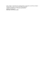
STAGE ONE:
During the fill cycle, fluid flows from the
receiving chamber (A) through the inlet
check valve (B) into the pumping
chamber (C). The 3-way valve (D) is
open between the pumping chamber
and the receiving chamber, equalizing
the pressure between them through the
equalizing line (E).
STAGE TWO:
When the level control (F) senses that
the pumping chamber is full, the 3-way
valve energizes to admit the motive
pressure into the pumping chamber (C).
The inlet check valve (B) prevents
backflow into the fill line.
The discharge cycle begins when
pressure inside the pumping chamber is
greater than in the discharge line. The
discharge check valve (G) opens and
fluid flows into the discharge line. During
this cycle, incoming condensate is stored
in the receiver.
STAGE THREE:
Once the level control (F) senses the
pumping chamber has emptied, the 3-
way valve (D) de-energizes, shutting off
the motive pressure, and opening the
vent port in the valve. This equalization
cycle allows the pumping chamber (C)
and the receiving chamber (A) to
equalize in pressure, and the fill cycle
begins again.
Installation
Preparation
For ease of future maintenance, the Liqui-Mover pump should be installed with the check valve side of the
pump tank most accessible. Normally the motive inlet and the condensate discharge connections are on the
left when facing the check valves. If a Johnson receiver is supplied, the replaceable sacrificial anode is also
installed and removed from this end. On ERC and FAC (pneumatic operated 3-way valve) units, the control
air is located on the right when facing the check valves. Refer to the enclosed assembly drawing for addi-
tional information.
Setting the Unit
On LOOO models, the pump tank has (4) holes for mounting to the floor.
On LROO models, you will also need to install a Johnson supplied receiver. The receiver is held in saddles
with ‘U’ bolts supported by (4) pipes on floor flanges. The floor flanges have mounting holes for attachment
to the floor.
On LRFP models, the entire base of the frame should be supported. Mounting holes can be drilled through
the frame base for attachment to the floor.
All tanks should be installed level.
Piping
On LROO and LRFP models, the Johnson supplied receiver will normally have (3) top connections for: con-
densate inlet, atmospheric vent, and pressure gauge. For ‘closed systems’ (no atmospheric vent), an air
eliminator and safety relief valve will need to be installed. On LOOO models, the condensate is piped direct-
ly to the inlet check valve from an existing receiver or pipe accumulator.
The motive pressure (normally steam or compressed air) is piped to the 3-way valve through a strainer and
a pressure reducing valve. The strainer is supplied on LRFP models. Compressed air of at least 55 psig
should be piped to the pilot valve through a filter/regulator/lubricator on ERC and FAC models. The pilot
valve and the filter/regulator/lubricator are supplied with the unit.
For LROO and LOOO models, friction loss through the piping should be kept to a minimum. Therefore, pipe
reducers should not be used and pipe runs kept to a minimum. All hand valves should be full port if at all
possible.
Electrical
Connect the electrical service to the on/off switch located on the door of the electrical enclosure per the
instruction label located near the switch. The electrical voltage must be the same as the rating of the level
control relay and the valve, unless a step-down transformer has been supplied.
NOTE: An on/off switch is not standard on NEMA 7 units.
Pressure Reducing Valve Installation
A pressure reducing valve (PRV) should be installed in the motive pressure line to regulate how fast the
Liqui-Mover pump discharges the condensate out of the pump tank. When properly adjusted, the discharge
time should not be less than 20 seconds. A longer discharge time is acceptable, so long as the Liqui-Mover
pump can keep up with the incoming condensate load. Normally the motive pressure setting will be approx-
imately 20 psig higher than the back pressure to achieve a 20 second discharge time.
Here are some guidelines to be followed when installing a PRV in conjunction with a Liqui-Mover pump:
1. Never install a PRV immediately adjacent to the 3-way motive valve. The shock caused by the
sudden opening and closing of the motive 3-way valve will ultimately damage the PRV. We rec-
ommend a distance of 20-25 feet between the PRV and the 3-way valve, where the pipe size
is the same as the 3-way valve connection. A larger diameter pipe of a shorter length that has
an equivalent volume is also acceptable. The PRV should be sized by a pressure reducing
valve manufacturer or representative.
2. A safety relief valve should be installed downstream of the PRV to prevent over-pressurization
at the 3-way valve. The safety relief valve should be sized by a safety relief valve manufactur-
er or representative.
3. When steam is the motive pressure, a drip trap, dirt leg, and strainer should be installed ahead
of the PRV. The drip trap should not
be piped to the Liqui-Mover pump, unless the receiver is
vented. When compressed air is the motive pressure, a liquid drainer, dirt leg, and strainer should
be installed ahead of the PRV. The liquid drainer should not be piped to the Liqui-Mover pump.
4. The piping from the PRV outlet to the 3-way valve inlet should be sized to minimize the pres-
sure drop under ‘flow conditions’.
5. A throttling valve should be installed immediately ahead of the 3-way motive valve so it can be
used in conjunction with the PRV to adjust the Liqui-Mover pump discharge time. Typically the
throttling valve is a globe valve.
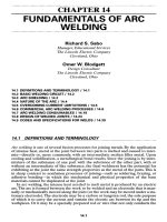
The above sketch is for reference only. Always consult with the PRV and safety relief valve manufacturer or
representative for proper sizing and application of their products.
Motive Supply Header - Steam or Compressed Air
Safety Relief Valve
(Piped to safe location)
Dirt Leg
Y Strainer
Drip Trap(Steam) or Liquid Drainer(Air Motive)
PRV
Equalization Line
To Receiver /
Condensate Header
To Liqui-Mover Pump
Throttle Valve
(Globe)
3-Way Valve
20´ – 25´
Printed on 12/15/2008 at 11:41:12 AM Property of Kadant Johnson - Confidential
Installation Diagram for Liqui-Mover Pump with Compressed Motive
Safety Relief Valve
(When Needed)
This Connection Required For
Liqui-Mover Pumps Having a Pneumatic
Operated 3-Way Valve (ERC and FAC units)
Regulator w/ Gage
Filter w/ Auto Drain
Motive - Compressed Air Supply
Liqui-Mover Pump
To 1/4" NPT Air
Inlet Connection of
Liqui-Mover Pump
Throttle Valve
(Globe)
To Motive Inlet
of Liqui-Mover Pump
1. This is the recommended piping for a Liqui-Mover pump with compressed motive.
2. The air should be clean, dry and regulated so that the Liqui-Mover pump discharges in the
recommended time.
3. The above parts furnished by customer.
NOTE:
1. The above sketch is for reference only.
2. Additional isolation hand valves may be added as required for maintenance purposes.
3. Globe valves should be used where flow restriction is required.
4. Gate valves should be used where minimal flow restriction is required.
5. For proper PRV installation, see manufacturers installation instructions.
Start-Up Instructions
1. On Liqui-Mover pumps that are not pre-piped, inspect the inlet and outlet check valves for
proper flow direction. Refer to the Liqui-Mover pump assembly drawing and parts list.
2. If the receiver and/or pump tank contains sub-cooled condensate, this needs to be drained
prior to start-up.
3. On ERC and FAC units, open the compressed air line to the filter/regulator/lubricator and set
the air pressure to 55 psig, minimum.
4. On ERC and ERS units, turn on the electrical power.
5. Open the motive steam or compressed air supply to the PRV and set the pressure to approx-
imately 20 psig higher than the back pressure. The throttling (globe) valve should be closed.
6. Open all remaining isolation (hand) valves, except the isolation valve ahead of the inlet check
valve (fill line).
7. Once condensate in seen in the receiver, slowly open the isolation valve in the fill line and
watch for condensate to fill the pump tank.
8. When the 3-way motive valve energizes, slowly open the throttling (globe) valve ahead of the
3-way motive valve. This will allow the pump tank to discharge.
9. After a few discharge cycles, you will be able to fully open the throttling valve and set the
motive pressure to achieve a 20-25 second discharge time using the PRV.
10. The unit is now in service.
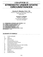
Discharged
Condensate
Equalize Line
Drip Trap - Steam
Liquid Drainer - Air
Strainer
Globe Valve
PRV
Motive Supply
Check Valve
Outlet
Check
Valve
Receiver
May Be JoCo ASME Labeled
Receiver, Existing Receiver,
Oversized Pipe Header, or Etc.
3-Way Motive Valve
Pumping Tank
Control
Panel
Vent Line
Incoming Condensate
Inlet
Check
Valve
TYPICAL INSTALLATION SKETCH
CV3S-1000 Series with 4-Way Pilot Valve
Port 3
(Motive In)
Port 2 (Equalize)
Port 1 (Common)
A
B
IN
A
EXB
Filter/Regulator/Lubricator
Solenoid Pilot Valve
4-Way
Port 2 (Equalize)
Port 3
(Motive In)
Port 1 (Common)
BEX
A
IN
B
A
Solenoid Pilot Valve
4-Way
Filter/Regulator/Lubricator
CV3S-100 Series with 3-Way Pilot Valve
3
2
1
Filter/Regulator/Lubricator
Motive In
Equalize
Common
Solenoid Pilot Valve
3-Way
3
1
2
Motive In
Equalize
Common
Solenoid Pilot Valve
3-Way
Filter/Regulator/Lubricator
Pilot De-Energized
Pilot Energized
Pilot De-Energized
Pilot Energized
Coil Voltage Freq. Coil No. Approx. Current Fuse Service JOCO Fuse No.
Size (Amps) (Amps)
Inrush Sealed
B4 120 60 31 5.6 0.54 0.8 Cont. CSE175-3025-03
B4 240 60 32 2.8 0.27 0.5 Cont. CSE175-3025-08
B4 240 50 32-50 2.8 0.27 0.5 Cont. CSE175-3025-08
C4 120 60 595 12.7 1.00 1.25 Cont. CSE175-3025-04
C4 240 60 596 6.4 0.50 0.8 Cont. CSE175-3025-03
C4 240 50 596-50 6.4 0.50 0.8 Cont. CSE175-3025-03
D7 120 60 61 12.0 1.04 1.4 Cont. CSE175-3025-05
D7 240 60 62 6.0 0.53 0.8 Cont. CSE175-3025-03
D7 240 50 62-50 6.0 0.53 0.8 Cont. CSE175-3025-03
D3 120 60 71 20.0 1.82 2.50 Cont. CSE175-3025-06
D3 240 60 72 10.0 0.92 1.25 Cont. CSE175-3025-04
D3 240 50 72-50 10.0 0.92 1.25 Cont. CSE175-3025-04
D4 120 60 81 33.5 4.57 6.0 Int. * CSE175-3025-07
D4 240 60 82 16.8 2.35 3.0 Int. * CSE175-3025-09
D4 240 50 82-50 16.8 2.35 3.0 Int. * CSE175-3025-09
Int. * : Intermittent service - solenoid energized not over 45% of the time and not longer than 1/2 hour at one time
Fuses manufactured by: Gould Shawmut TR XX R
Bussman FRN-R-XX
(Replace X's with Fuse Amps)
Reference Johnson Drawing A37786
Johnson Solenoid Coil and Fuse Specification Sheet
Troubleshooting
Contents
General Troubleshooting
General ERC and ERS Troubleshooting
ERC Troubleshooting
ERS Troubleshooting
FAC Troubleshooting
Preventative Maintenance Check List
Preventative Maintenance Check List Additional For FAC
Ceramic Electrode Plugs
Electrode Lengths
8300 Series Relay Installation and Maintenance
Intrinsically Safe Relay Installation and Maintenance
Page 1 - General Troubleshooting LMTSO387-03
OBSERVATION PROBABLE CAUSE REMEDY
1. Liqui-Mover pump fails to fill. 1. Increase in liquid level in
receiver, possible flood in
receiver.
Obstruction in fill line, valve closed,
inlet check valve backwards.
Inspect fill line for closed valve, inlet
check valve in reverse, or obstruction
in fill line. Refer to Assembly & Parts
List Drawing.
2. Increase in liquid level in
receiver, possible flood in
receiver, increase in receiver
pressure.
3-Way Valve Assembly out of
adjustment.
Inspect 3-Way Valve Assembly.
Refer to Valve Section.
3. Receiver empty.
Liqui-Mover pump level
fluctuating.
Receiver pressure greater than
pressure in discharge line.
If unit has been in operation for a
period of time without problems,
check for traps blowing through. If
new installation receiver pressure may
be greater than anticipated. Back
pressure may be less than anticipated.
A 2-Way Controlled Valve may be
required in discharge line.
4. 3-Way Motive Valve will not
deenergize.
See observation under specific ERS
or ERC Troubleshooting Section.
See specific remedy.
2. Liqui-Mover pump fills too
slow.
1. No liquid level in receiver. Load to unit not as great as
anticipated.
No action required.
2. Receiver flooding. Obstruction or restriction in fill line. Inspect fill line for partially closed
valve or defective check valve.
Inspect fill line for proper size fittings
and pipe. Refer to Assembly and
Parts List Drawing for specific unit.
GENERAL TROUBLESHOOTING OF LIQUI-MOVER
PUMPS
Page 2 - General Troubleshooting LMTSO387-03
OBSERVATION PROBABLE CAUSE REMEDY
3. Receiver flooding. Restriction in vent line, 3-Way Valve
assembly out of adjustment.
Inspect vent line for partially closed
valve, proper size fittings and pipe.
Refer to Assembly and Parts List
Drawing. Inspect 3-Way Valve
Assembly. Refer to Valve Section.
3. Liqui-Mover pump fills very
rapidly.
1. Unit cycling almost
normally, receiver flooding.
Defective check valve in discharge line
and/or fill line. Possible back flow to
Liqui-Mover pump.
Inspect discharge line check valve and
fill line check valve. Refer to
Assembly and Parts List Drawing.
4. Noise in or at fill line check
valve.
1. Vibration and water hammer
at fill line check valve.
Cold condensate. Inspect for cold condensate. Throttle
flow control valve, ahead of 3-Way
Motive Valve Assembly. Refer to
Assembly and Parts List Drawing,
and start-up procedure.
5. Liqui-Mover pump discharges
very rapidly.
1. Water hammer in discharge
line.
Motive pressure too high. Throttle flow control valve or install
pressure reducing valve. See start-up
procedure.
2. Receiver flooding, rise in
receiver pressure during
discharge.
Defective check valve in fill line,
discharging condensate back into
receiver.
Inspect fill line check valve. Refer to
Assembly and Parts List Drawing.
6. Liqui-Mover pump discharge
cycle too long.
1. Possible receiver flooding,
discharge time greater than
30 seconds.
Flow control valve throttled too much. No action required, if receiver not
flooding. If receiver flooding, adjust
flow control valve for discharge of
20 - 25 seconds (approx.).
Page 3 - General Troubleshooting LMTSO387-03
OBSERVATION PROBABLE CAUSE REMEDY
2. Receiver flooding. Discharge
time greater than 30 seconds.
Restriction or increase of back
pressure in discharge line.
Inspect discharge line for partially
closed valve(s), obstructions or
change in pressure. A pressure
increase may require adjustment of
flow control valve to reduce discharge
time. Inspect discharge check valve.
3. No motive pressure flow.
Receiver flooding.
Motive supply failure, obstruction in
motive supply line.
Inspect for motive supply pressure,
closed valve, or obstruction in motive
supply line. Inspect strainer.
4. 3-Way Motive Valve noisy. Condensate in motive supply line. Inspect motive supply line for
condensate. Check drip trap. Refer to
Assembly and Parts List Drawing.
5. Receiver pressure increase
during discharge.
3-Way Valve out of adjustment,
leakage into receiver.
Refer to Valve Section.
6. 3-Way Motive Valve will not
deenergize.
See observation under specific Relay
Section.
See specific remedy.
Page 4 - ERC or ERS Troubleshooting LMTSO387-03
GENERAL ERC & ERS TROUBLESHOOTING
OBSERVATION PROBABLE CAUSE REMEDY
1. 3-Way Valve erratic.
Operates from one level only.
1. Condensate level in
Liqui-Mover pump at one
level.
Electrode wires reversed. Poor
ground connection.
Refer to Relay Troubleshooting
Section.
2. 3-Way Valve erratic. Operates
from low level only.
1. Condensate level in Liqui-
Mover pump at low level.
Electrode plugs shorted. Electrode
plug grounded. Holding contact bad.
Refer to Relay Troubleshooting
Section.
3. 3-Way Valve erratic. 1. Condensate level can be high
or low.
Moisture in electrode holder. Dirty
electrodes. Cracked or broken
electrode plug.
Refer to Relay Troubleshooting
Section.
Page 5 - ERC Troubleshooting LMTSO387-03
TROUBLESHOOTING – ERC UNITS
(w/Electrodes-Relay-Cylinder Operated Valves)
OBSERVATION PROBABLE CAUSE REMEDY
1. 3-Way Cylinder Operated Valve
will not cycle on (closed
motive side – open vent side).
1. Relay pulls in. Air pilot
shifts.
Packing nut too tight. Back-off packing nut. Refer to Valve
Section.
2. Relay pulls in. Air pilot
shifts.
Obstruction in air line to cylinder. Check air lines for obstructions or
breaks.
3. Relay pulls in. Air pilot
not shifting.
Air pilot valve. Check wiring, check for voltage to
pilot coil. Check air pressure (55 psig
minimum).
4. Relay will not pull in. Power failure. Refer to Relay Troubleshooting
Section.
5. Relay will not pull in. Electrode circuit or relay malfunction. Refer to Relay Troubleshooting
Section.
2. 3-Way Cylinder Operated Valve
will not cycle off (open motive
side – closed vent side).
1. Relay drops out. Air
pilot shifts.
Packing nut too tight. Back-off packing nut. Refer to Valve
Section.
2. Relay drops out. Air
pilot not shifting.
Air supply or air pilot valve. Check for proper air pressure. Inspect
relay contacts for being welded
together. If okay, repair or replace
pilot valve.
3. Relay drops out. Air
pilot shifts. Receiver
flooding.
3-Way Cylinder Valve Assembly
jammed.
Inspect 3-Way Cylinder Valve
Assembly for obstruction, dirt or
foreign debris. Refer to Valve Section.
4. Relay will not drop out.
Receiver flooding.
Electrode holder wet or dirty, probe or
wire grounded.
Refer to Relay Troubleshooting
Section.
3. 3-Way Cylinder Operated Valve
cycles On–Off erratically.
1. Relay does not follow
erratic valve operation.
Air supply fluctuating. Inspect air supply for fluctuations. Air
pilot requires 55 psig minimum.
Page 6 - ERS Troubleshooting LMTSO387-03
TROUBLESHOOTING – ERS UNITS
(w/Electrodes-Relay-Solenoid Steam Valve)
OBSERVATION PROBABLE CAUSE REMEDY
1. 3-Way Valve will not energize
(closed motive side – open vent
side).
1. Relay pulls in. Liqui-Mover
pump flooded.
Overload tripped or fuse bad. Replace fuse. Refer to Valve Section.
2. Relay pulls in. Solenoid
valve noisy.
Packing nut too tight. Dirty armature. Back-off packing nut. Refer to Valve
Section. Check valve adjustment.
3. Relay pulls in. Fuse not
blown.
Solenoid valve coil open. Inspect Solenoid Valve for burnt or
broken lead wires or bad coil. Inspect
Solenoid Valve for mechanical jam.
Refer to Valve Section.
4. Relay will not pull in. Power failure. Inspect for supply voltage. Refer to
Relay Troubleshooting Section.
5. Relay will not pull in. Electrode circuit or relay malfunction. Refer to Relay Troubleshooting
Section.
2. 3-Way Valve will not
deenergize (open motive side –
close vent side).
1. Relay drops out. Receiver
flooding.
Packing nut too tight. Back off packing nut. Refer to Valve
Section.
2. Relay will not drop out.
Receiver flooding.
Electrode holder wet or dirty, probe
or wire grounded.
Refer to Relay Troubleshooting
Section.
3. Relay will not drop out.
Receiver flooding.
Electrodes shorted. Inspect Liqui-Mover pump chamber
for debris. Refer to Relay
Troubleshooting Section
4. Relay drops out. Receiver
flooding.
3-Way Steam Valve Assembly
jammed.
Inspect 3-Way Solenoid Valve
Assembly for obstruction, dirt, or
foreign debris. Refer to Valve Section.
Page 7 - FAC Troubleshooting LMTSO387-03
TROUBLESHOOTING – FAC UNITS
(Refer to General Troubleshooting Section, Pages 1 through 3, then the following.)
OBSERVATION PROBABLE CAUSE REMEDY
1. 3-Way Cylinder Operated Valve
will not cycle on (closed motive
side – open vent side).
1. Air pilot shifts. Air pressure too low. Raise air pressure.
2. Air pilot shifts. Packing nut too tight. Back-off packing nut. Refer to Valve
Section.
3. Air pilot shifts. Obstruction in air line to cylinder. Check air lines for obstructions or
breaks.
4. Air pilot not shifting. Wisker valve not operating or bad. Break air line between pilot valve and
wisker valve.
1. If pilot valve still does not shift,
break air line between air filter and
choke. Clean .010˝ hole in choke or
replace choke. Reassemble and
retest. If pilot valve still does not
shift, replace pilot valve.
2. If pilot valve shifts, shut off all
steam, condensate, and motive lines
to and from the unit. Reconnect the
air line between the pilot valve and
the wisker valve. Remove the cover
(LMH-02032-1 or 6) and manually
raise the float tube.
Page 8 - FAC Troubleshooting LMTSO387-03
OBSERVATION PROBABLE CAUSE REMEDY
a. If the pilot valve shifts,
disassemble flanges that mount
the control head and remove,
inspect, and repair float
assembly as required. Refer to
Dwg. A-97-19-4-17, Pg. 5.
b. If the pilot valve does not shift,
remove the air switch and
inspect for missing or broken
spring pins, magnet, or snap
rings. Note: The magnet must
be able to rotate freely only 30
degrees. If all appears proper,
replace the wisker valve, Refer
to Dwg. A-97-19-4-17, Pg. 3.
2. 3-Way Cylinder Operated Valve
will not cycle off (open motive
side – closed vent side).
1. Air pilot shifts. Low air pressure. Raise air pressure.
2. Air pilot shifts. Packing nut too tight. Back-off packing nut. Refer to Valve
Section.
3. Air pilot shifts. Obstruction in air line to cylinder. Check air lines for obstructions or
breaks.
4. Air pilot not shifting. Wisker valve not operating or bad. Break the air line between the pilot
valve and the wisker valve. Block off
air flow from the fitting on top of the
pilot valve.
Page 9 - FAC Troubleshooting LMTSO387-03
OBSERVATION PROBABLE CAUSE REMEDY
1. If pilot valve does not shift, replace
the pilot valve.
2. If the pilot valve shifts, shut off all
steam, condensate, and motive lines
to and from the unit. Reconnect the
air line between the pilot valve and
the wisker valve. Remove the cover
(LMH-02032-1 or 6) and manually
lower the float tube.
a. If the pilot valve shifts,
disassemble flanges that mount
the control head and remove,
inspect, and repair float
assembly as required. Refer to
Dwg. A-97-19-4-17, Pg. 5.
b. If the pilot valve does not shift,
remove the air switch and
inspect for missing or broken
spring pins, magnet, or snap
rings. Note: The magnet must
be able to rotate freely only 30
degrees. If all appears proper,
replace the wisker valve. Refer
to Dwg. A-97-19-4-17, Pg. 3.
LIQUI-MOVER
PUMP
PREVENTATIVE MAINTENANCE CHECK LIST
HOW OFTEN CHECK REFERENCE
6 Months 1. Check electrodes for build up of
foreign matter. With build up, poor
conductivity may occur creating
erratic pumping behavior.
Remove cap on electrode holder.
Remove electrode plugs, this will also
remove electrodes. Clean electrodes
with steel wool or emery cloth.
Replace.
2. Check 3-Way valve adjustment and
make necessary adjustments. Also
check valve packing and replace if
required.
Refer to specific valve repair and
maintenance guide.
1 Year 1. Check electrical wiring.
Inspect wires at electrode plugs and
valve for a deterioration of insulation
and frayed wires.
2. Check anode in receiver tank. Drain tank – remove anode by
unscrewing anode plug on the receiver
tank end. If over 60% eaten away,
replace.
3. Clean gauge glasses when required. Disassemble and pull clean cloth
through glass with cleaning wire.
4. Drain tanks to remove residue. Remove drain plugs in bottom of both
tanks. Replace.
5. Check relay contacts (points). If dirty, clean. if burnt, replace, (ERS
units only).
6. Check Solenoid Valve current. With Solenoid Valve energized,
measure current. Too high a current
could indicate a dirty armature or worn
armature – clean or replace as
necessary. Refer to A-97-23-1-10 in
Valve Section.
CAUTION: Before performing any of the above maintenance checks, shut off electrical
power, steam, and condensate ahead of the unit.
Page 2 – Preventative Maintenance
FAC LIQUI-MOVER
PUMP
PREVENTATIVE MAINTENANCE CHECK LIST
HOW OFTEN CHECK REFERENCE
1 Month 1. Oiler Level. Should deliver (1) drop per week.
Adjustment screw.
2. Air Filter – Main. Blow down or clean as required.
3. Air Filter – Secondary.
(Located on Control Head)
Blow down or clean as required.
6 Months 1. Flush External Float Housing. Remove 1-1/2˝ drain plug and flush.
CAUTION:
These items in addition to standard Liqui-Mover pump maintenance check items.
Before performing any of the above maintenance checks, shut off all steam,
condensate and air lines.
CAUTION: Since Line Voltage is often present during electrical tests, only qualified electricians should per-
form electrical tests.
A. OPERATION – This description applies to a pump down or direct type of level control. The sequence is
as follows:
1. The relay is deenergized as shown in the diagram and the valve is deenergized and closed while the
liquid in the tank is rising.
2. When the liquid reaches the high level electrode, it completes the circuit from terminal 5 to 3, ener-
gizing the relay. This can be heard as a click as the load contact is reversed.
3. The load contact closes and the valve opens admitting pressurized steam or air into the tank which
causes the liquid level to lower.
4. When the relay energized, an internal “holding” circuit closed from terminal 4 to 3. When the liquid
leaves the high level electrode this “holding” circuit through the ground, the liquid, and the low level
electrode keeps the relay energized.
5. When the liquid drops below the low level electrode this holding circuit is broken and the relay is
deenergized, opening the load contact.
6. The valve closes, shutting off the pressurized gas line and allowing the liquid to rise again.
B. RELAY DOES NOT PULL IN
1. POWER FAILURE – Check for voltage at the two (2) terminals located on the lower left hand corner
of the level control relay. This voltage should be either 120 or 240 volts A.C. as determined by the
voltage of the relay(s) and solenoid operated valve(s).
2. DEFECTIVE LEVEL CONTROL – Disconnect the electrodes and jumper the terminal marked “C” to
the terminal marked “H”. The 3-way steam valve should turn on when the jumper is connected and
shut off when the jumper is removed. To check the holding circuit proceed as above but do not
remove the jumper wire; instead add another jumper wire from the terminal marked “C” to the termi-
nal marked “L”. Remove the first jumper wire connected to “H” and the relay should remain energized.
If the relay does not remain energized, it is bad and will have to be replaced.
BLACK
WHITE
A.C. Line
1
LCR
2
LCR
AUX PWR RELAY
SOV1
LCR
OPT. COUNTER
3
4
5
to SHORT ELECT.
to LONG ELECT.
GND. & ELECT.
APR
APR
FU
OPT. CYCLE COUNTER
10
9
8300 Series Relay Installation and Maintenance
Black
White
A.C. Line
1
LCR
2
LCR
SOV1
OPT. CYCLE COUNTER
LCR
OPT. COUNTER
9
10
3
4
5
to SHORT ELECT.
to LONG ELECT.
GND. & ELECT.
ERC ERS
3. POOR GROUND CONNECTION – The control will not function unless a good dependable ground
connection is made to the terminal marked “C”. When installed in non-conductive tanks a third elec-
trode (the longest) is required for a ground connection.
4. BROKEN WIRES – Check for broken wires by grounding the spark plug holding the short electrode.
If the relay fails to energize, one or both of the electrode leads are open, or there is a bad ground
connection. Run temporary wires from the control panel to the electrode holder and retest.
5. BUZZ OR CHATTER – If the resistance or conductivity of the liquid is too low, the relay may buzz,
chatter, or fail to operate at all. Consult area representative for selecting a relay with proper sensi-
tivity.
6. FOULED ELECTRODES – Accumulated dirt, oil, and other deposits may insulate the electrodes and
prevent operation. Electrodes should be inspected and cleaned at regular intervals.
C. VALVE DOES NOT ENERGIZE WHEN THE RELAY DOES
1. FUSE – ERS – ERS units are equipped with a fuse for solenoid valve coil protection. Check the
fuse for continuity and replace if bad. One spare is included with each Liqui-Mover pump. Refer
to Drawing A-27541, Symbol No. A-97-23-1-15 for solenoid coil protection.
2. SOLENOID COIL – Remove the wires going to the solenoid coil from the terminal strip and check
for continuity. If an open circuit is found, there is a broken wire, a bad connection, or the coil itself
is bad. Repair or replace as necessary.
3. AUXILIARY RELAY – ERS – ERS units are equipped with an auxiliary relay because the level
control relay contacts are not heavy enough to handle the inrush current of a direct operated
solenoid valve. Inspect this relay for burnt contacts. Clean or replace contacts/relay as required.
D. VALVE ENERGIZED WHEN RELAY IS NOT ENERGIZED
1. RELAY CONTACTS – The relay contacts may have failed to open. On ERS units inspect the aux-
iliary relay visually for stuck contacts. On ERC and ERS units check the contacts on the level con-
trol relay with a V.O.M.
E. RELAY WILL NOT DEENERGIZE
1. GROUND WIRE – A wire from the relay to an electrode may be grounded to the conduit or enclo-
sure.
2. WET PLUG – Dirt or moisture on an electrode plug can ground the electrode to the holder.
Cleaning the electrode plugs periodically and using a proper holder will help keep the plugs
clean.
3. CRACKED PLUG – The electrode plug may be cracked, allowing moisture to ground the elec-
trode to the enclosure.
F. RELAY FLUCTUATES AT HIGH LEVEL
1. ELECTRODE WIRING – Wire to low level electrode may be broken.
2. ELECTRODE – Low level electrode may have broken off or become insulated due to grease or
dirt.
3. RELAY HOLDING CIRCUIT – If the internal holding circuit of the relay fails to close, the relay
would fluctuate at the high level. To test relay see Section B-2.
G. RELAY FLUCTUATES AT LOW LEVEL
1. WIRES REVERSED – Wires to electrodes may be reversed.
2. RELAY HOLDING CIRCUIT – If the internal holding circuit of the relay is shorted, it would cause
the relay to fluctuate at the low level. To test the relay see Section B-2.
H. RELAY CHATTERS AFTER DISCHARGING
1. WET PLUG – The underside of the electrode plug may be coated with dirt or moisture causing
continuity across the insulator. If steam is used as the motive substance to lower the liquid level,
when the tank is vented at the start of the fill period the steam expands. This may leave a film of
moisture on the underside of the plug which can cause relay fluctuation a few times before the mois-
ture evaporates and lets the relay drop out. This can be avoided by using a relay with lower sensi-
tivity if the liquid is sufficiently conductive, or by insulating the electrodes, leaving 1/4˝ bare at the
lower end.
INSTALLATION – The electrode circuit of this relay is intrinsically safe and can be located in a hazardous
area with an electrode holder and tank which are not explosion-proof. However, the rest of the circuits must
be protected by explosion-proof enclosures and rigid conduit with conduit seals.
OPERATION – This description applies to a “pump down” type of level control and the sequence is as fol-
lows:
1. The relay is deenergized as shown in the diagram and the valve is deenergized and closed while the
liquid in the tank is rising.
2. When the liquid reaches the high level electrode, it completes the circuit from terminal 14 to 15, ener-
gizing the relay. This can be heard as a click and all the load contacts are reversed.
3. Load contact 10 – 7 closes and the valve opens admitting pressurized steam or air which causes the
liquid level to lower.
4. When the relay was energized, an internal “holding” circuit closed from terminal 16 to 15. Hence
when the liquid leaves the high level electrode this “holding” circuit through the ground, the liquid,
and the low level electrode keeps the relay energized.
5. When the liquid drops below the low level electrode this holding circuit is broken and the relay is deen-
ergized, opening the internal holding connection from 14 to 16 and opening load contact 10 – 7.
6. The valve closes, shutting the pressurized gas line and allowing the liquid to rise again. When the
liquid reaches the low level electrode the relay remains deenergized since the internal connection
from 16 to 15 is now open, so the cycle will be repeated.
INTRINSICALLY SAFE RELAY FOR LEVEL CONTROL
120 V
AC
11
12
13
14
15 16
6
5
4
3
9
Sol.
Valve
Electrode Holder
High Level Electrode
Low Level Electrode
10
8
7
B
Fuse
240 V
AC
11
12
13
14
15 16
6
5
4
3
9
B
Sol.
Valve
10
8
7
Fuse
*
Note: For ERC type units no overload is used.
The air pilot valve is connected to relay termi-
nals 11 and 7 or as shown on wiring assembly.
Older models use a thermal element in place of
the fuse shown.
A
B