simulation of magnetic hysteresis loops and magnetic barkhausen noise of iron containing nonmagnetic particles
Bạn đang xem bản rút gọn của tài liệu. Xem và tải ngay bản đầy đủ của tài liệu tại đây (2.28 MB, 8 trang )
Simulation of magnetic hysteresis loops and magnetic Barkhausen noise of α−iron
containing nonmagnetic particles
,
Yi Li, Ben Xu, Shenyang Hu, Yulan Li, Qiulin Li, and Wei Liu
Citation: AIP Advances 5, 077168 (2015); doi: 10.1063/1.4927548
View online: />View Table of Contents: />Published by the American Institute of Physics
AIP ADVANCES 5, 077168 (2015)
Simulation of magnetic hysteresis loops and magnetic
Barkhausen noise of α-iron containing nonmagnetic
particles
Yi Li,1,2 Ben Xu,1 Shenyang Hu,3 Yulan Li,3 Qiulin Li,1,2 and Wei Liu1,2,a
1
School of Material Science and Engineering, Tsinghua University, Beijing, 100084, China
Graduate School at Shenzhen, Tsinghua University, Shenzhen, 518055, China
3
Energy Materials Division, Pacific Northwest National Laboratory, Richland,
WA, 99352, USA
2
(Received 10 April 2015; accepted 15 July 2015; published online 24 July 2015)
The magnetic hysteresis loops and Barkhausen noise of a single α-iron with nonmagnetic particles are simulated to investigate into the magnetic hardening due to Cu-rich
precipitates in irradiated reactor pressure vessel (RPV) steels. Phase field method
basing Landau-Lifshitz-Gilbert (LLG) equation is used for this simulation. The
results show that the presence of the nonmagnetic particle could result in magnetic
hardening by making the nucleation of reversed domains difficult. The coercive field
is found to increase, while the intensity of Barkhausen noise voltage is decreased
when the nonmagnetic particle is introduced. Simulations demonstrate the impact of
nucleation field of reversed domains on the magnetization reversal behavior and the
magnetic properties. C 2015 Author(s). All article content, except where otherwise
noted, is licensed under a Creative Commons Attribution 3.0 Unported License.
[ />
I. INTRODUCTION
A central issue in safe operation of nuclear power plants is the evaluation of structural components integrity. Of particular concern is the reactor pressure vessel (RPV) which suffers from
neutron irradiation embrittlement induced by the nano-sized Cu-rich precipitates.1–3 Currently, the
embrittlement of RPV is evaluated by the ductile–brittle transition temperature (DBTT) shift1,4
which is obtained from Charpy impact tests for surveillance samples installed in the RPV. In
fact, the surveillance samples are subject to a higher dose rate of neutron irradiation than the
RPV itself, but the dose rate effect has not yet been revealed completely,5–7 which reduces the
reliability of the current surveillance technology. Another concern is the diminishing stock of
the Charpy samples when nuclear power plants are extended to operate beyond their designed
lifetime.8 As a consequence, it is of great meaning to monitor the embrittlement of RPV itself online
and nondestructively.
Measurements of material magnetic properties change can be a good candidate method for
nondestructive monitoring of the microstructure change of irradiated structural materials. Based on
the investigations into the irradiated RPV steels, the coercive field tends to increase after high dose
neutron irradiation.9–13 Another magnetic property, magnetic Barkhausen Noise (MBN) voltage, is
found to decrease after the irradiation.14–16 Both of these magnetic properties change are due to the
nano-sized nonmagnetic precipitates.12,17,18 These results indicate that magnetic technology could
be a promising nondestructive evaluation (NDE) tool to monitor the RPV embrittlement induced by
nonmagnetic precipitates.
The experimental results mentioned above are somewhat encouraging. However, the fundamental mechanism of how nano-sized nonmagnetic particles affect the magnetic response of α-Fe
is still unrevealed and needs to be understood before reliably using the technology. The motivations
a Corresponding author.
2158-3226/2015/5(7)/077168/7
5, 077168-1
© Author(s) 2015
077168-2
Li et al.
AIP Advances 5, 077168 (2015)
for this study are to use phase field method for simulating the hysteresis loops and MBN voltage in
α-Fe containing nano-sized nonmagnetic particles, and to improve the fundamental understanding
of magnetic hardening mechanism and signal physics in irradiated RPV steels, which is important
for the development of advanced NDE technology for monitoring the irradiation embrittlement of
RPV.
II. SIMULATION DETAILS
A model system of single crystal α-Fe containing nonmagnetic particles was simulated. The
nonmagnetic particles could be Cu or Cr precipitates, voids or carbides. For simulating a magnetic
hysteresis loop, the average magnetization of the simulation volume is calculated at each magnetic
field. The magnetization of the grid is obtained by solving the following Landau-Lifshitz-Gilbert
(LLG) equation,19,20
1 + α2
∂M
γ0 α
= −γ0M × Heff −
M × M × Heff
∂t
Ms
(1)
where M is magnetization vector, Ms is the saturation magnetization of the magnetic phase, γ0 is
the gyromagnetic ratio, α is the dimensionless damping constant, and Heff is the effective magnetic field, which is the derivative of the total free energy F of the system with respect to the
magnetization,
Heff = −
1 δF
µ0 δM
(2)
where µ0 is the permeability of vacuum. The total energy is calculated by
F = Fans + Fexch + Fmagn + Fextr
(3)
Where Fans, Fexch, Fmagn and Fextr are the magnetocrystalline anisotropy energy, exchange energy,
magnetostatic energy and external field energy respectively. Equation (1) is solved numerically by
a fractional step procedure of Gauss–Seidel approach and fast Fourier transform.20–22 The corresponding material constants used in the simulations can be found in previous work. 22
Magnetic Barkhausen Noise (MBN) is produced by discontinuous changes of the magnetization of ferromagnetic materials under the influence of a continuously variable Magnetic field,23 and
MBN voltage can be described as the time derivative of the magnetic flux dΦ/dt,24,25 where Φ is
the magnetic flux, which equals to the multiply of the magnetic flux density B and the area S of the
detecting coil. S is fixed during measurement and thus dΦ/dt is in proportion to dB/dt. For α-Fe,
the susceptibility is very large, so dB/dt almost equals to dM/dt. The simulated MBN signal is
obtained after passing the dM/dt signal through a digital Butterworth filter.23
III. RESULTS AND DISCUSSION
A simulation volume of 256 nm × 512 nm × 1 nm (x = 256 nm, y = 512 nm, z = 1 nm) with
the size of a grid of 1 nm × 1 nm × 1 nm was adopted in our simulations, and the periodic boundary
conditions (PBC) were applied in these three directions. One nonmagnetic particle in the central
and two 180◦ domain walls (DWs) of opposite direction were introduced as the initial magnetic
morphology because of PBC. A magnetic field was applied along the x-direction. Magnetization
process started from H x = 0, afterwards the magnetic field increased to the maximum magnetic
field in positive x-direction (+Hmax), and then decreased to the maximum magnetic field in negative x-direction (−Hmax), and finally back to +Hma x . The maximum magnetic field (Hmax) was
40 kAm−1, and the increment or decrement of magnetic field was 0.1 kAm−1.
The nonmagnetic particles are assumed to be of solid cylindrical shape of radius R because of
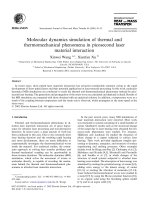
PBC. The hysteresis loops for the cases of R = 0, 3, 5, 9, 15 nm were plotted respectively in Fig. 1.
The corresponding coercive field (Hc ) dependence on the size of nonmagnetic particles was shown
in Fig. 1(b). In our simulation conditions, Hc is small and nearly unchangeable for the case with a
077168-3
Li et al.
AIP Advances 5, 077168 (2015)
FIG. 1. (a) Hysteresis loops for the simulated volume of 256 nm × 512 nm × 1 nm containing a nonmagnetic particle. The
radius of the particle is R = 0 (no particle inside), 3, 5, 9, 15 nm, respectively. (b) Summary of the coercive field versus
the radius of a nonmagnetic particle. (c) The domain morphologies of the marked points (S1, N1, P1; S2, N2, P2) on the
hysteresis loops of the cases with a particle of R = 0 and R = 5 nm in Fig. 1(a), respectively.
077168-4
Li et al.
AIP Advances 5, 077168 (2015)
particle of R < 3 nm, but it increases sharply and reaches a maximum, and then it decreases with the
particle size. Even though, Hc for the case with a particle of R = 30 nm is still larger than the case
without any particle (R = 0), which indicates that nonmagnetic particles could initiate magnetic
hardening in α-Fe.
The magnetization reversal process for the case of R = 0 and R = 5 nm is used as examples
to illustrated this magnetic hardening due to nonmagnetic particle. The domain morphologies of
the marked points in Fig. 1(a) were depicted in Fig. 1(c). The black arrows indicate the magnetization vector directions in x- y plane. The color represents the magnitude of the Mz component
(the magnetization in z-direction) as depicted by the color bar. For the case without any particles
(R = 0), the two opposite-direction 180◦ DWs formed a 360◦ DW when the magnetic field increased
to +Hma x (see Fig. 1(c)(S1)) , this 360◦ DW then acted as the nucleation site of reversed domain
during magnetization reversal process, as illustrated in Fig. 1(c)(N1). The nucleation field (Hn ) can
be found to be almost zero in this situation. For the case of R = 5 nm, the 360◦ DW annihilated
at the magnetic field of +Hmax (Fig. 1(c)(S2)) due to the presence of the nonmagnetic particle
which could prevent the formation or reformation of 360◦ DW.22 Around the nonmagnetic particle
there were two subsidiary spike domains26 where the magnetization vectors are perpendicular to
the x- y plane. As the magnetic field decreased to 0 from +Hma x , switched its direction to the
negative x-direction and increased its magnitude in this direction, the spike domains extended along
the x- direction until they reached the boundaries (Fig. 1(c)(N2)). After that, the spike domains
grew up along the y-direction and at the same time switched its magnetization vector to the negative x-direction, as demonstrated in Fig. 1(c)(P3), thus starting the magnetization reversal process.
Based on this process, the spike domains which are ready to expand along the y-direction can be
considered as the reversed domains, or in other words, the spike domains around the particle can act
as the nucleation site of reversed domains, and the corresponding magnetic field can be considered
as the nucleation field of the reversed domains. It can be found from Fig. 1(a) that Hn for the case
of R = 5 nm is much larger compared with that of R = 0, so the reversed domains are difficult to
nucleate and expand, leading to the magnetic hardening.
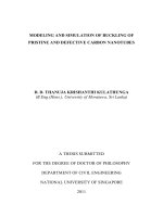
Fig. 2 shows the relationship between Hn and the nonmagnetic particle size. It can be found
that Hn is positive for the case of particles larger than 15 nm, in other words, the magnetic field
do not have to switch its direction to form the reversed domains, this facilitates the nucleation
of reversed domains from the nonmagnetic particles. Therefore the reversed domains are easier
to nucleate from the nonmagnetic particles if Hn is closer to +Hmax. In this work (+Hmax − Hn )
is used to evaluate the difficulty level of reversed domains nucleation, and the calculation results
are also plotted in Fig. 2. It can be seen that (+Hmax − Hn ) value is smaller for larger particles,
so the reversed domains form easier from larger particles. In addition, a linear relationship can be
found between Hn and the particle radius in Fig. 2. According to the study the reversed domains
FIG. 2. The dependence of the nucleation field of reversed domains (H n ) and (+Hmax − H n ) on the radius of nonmagnetic
particles. +Hmax is the maximum magnetic field in the positive x-direction and is used to evaluate the difficulty level of
reversed domains nucleation. The smaller (+Hmax − H n ) makes the nucleation of reversed domains easier.
077168-5
Li et al.
AIP Advances 5, 077168 (2015)
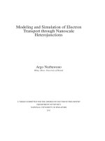
FIG. 3. Hysteresis loops for the cases with a particle of R = 7 nm (a) and R = 15 nm (b), respectively. The corresponding
simulated MBN voltage signals for the cases with a particle of R = 7 nm (c) and R = 15 nm (d), respectively.
nucleating from the grain boundary,27 Hn is proportional to the grain boundary area per unit volume,
or in other words, the boundary area of nucleation site per unit volume. Similarly, in our work, the
nucleation field of reversed domains from nonmagnetic particle can be considered to be linear with
the boundary area of the nonmagnetic particle per unit simulated volume. The boundary area in
our case is 2πR × 1 nm,2 and the simulated volume is fixed, so Hn is in line with the radius of the
particles.
Next we considered the effect of nonmagnetic particles on the simulated magnetic Barkhausen
Noise (MBN) signal. Fig. 3(a) and Fig. 3(b) demonstrated the hysteresis loops for the case of
R = 7 nm and R = 15 nm respectively. The corresponding simulated MBN voltage signals were depicted in Fig. 3(c) and Fig. 3(d). A MBN voltage peak usually appears when magnetization changes
drastically, such as at the coercive field and nucleation field. For the case of R = 7 nm, two MBN
peaks located at the coercive field in Fig. 3(c). But for the case of R = 15 nm, four MBN peaks
appeared in Fig. 3(d), two (peak 1 and 4) located at the coercive field, the other two (peak 2 and 3)
located at the nucleation field where two corresponding small kinks on hysteresis loop can be seen,
as indicated in the circle of Fig. 3(b). The number of MBN peaks depends on whether the reversed
domains can grow up immediately after nucleation. For the case of R = 7 nm, the magnetic field
had turned its direction to negative x-direction and increased its magnitude large enough to promote
the growing up of reversed domains immediately after nucleation, and hence only one MBN peak
formed. For the case of R = 15 nm, one MBN peak (peak 3) formed when the reversed domains
nucleated, but the magnetic field had not switched to the negative x-direction yet, so the growth
of reversed domains was suppressed by external field energy. When the magnetic field turned its
direction to the negative x-direction and increased in its magnitude, the reversed domains grew
up and produced a second MBN peak (peak 1) at the coercive field. Similarly, the magnetization
process from −Hmax to +Hmax would produce peak 2 and peak 4. The MBN peaks produced by
reversed domains nucleation have also been observed in simulated system including dislocations.28
Another phenomenon found from Fig. 3 is that the intensity of MBN voltage is different for
different cases. The root mean square (RMS) of MBN voltage at every magnetic field is often used
077168-6
Li et al.
AIP Advances 5, 077168 (2015)
FIG. 4. The dependence of the root mean square (RMS) of simulated MBN voltage signals on radius of the nonmagnetic
particles.
to evaluate the intensity of MBN voltage.14 The intensity of MBN voltage is decided by dMx /dt
which can represent the velocity of DW movement. The RMS of MBN voltage for all the simulated
cases is shown in Fig. 4, and it can be seen that RMS decreases with nonmagnetic particle size. According to Sakamoto,27 the mean velocity of DW is proportional to Hn once the DW motion begins
for the case of nucleation and growth mechanism. In our simulations for the cases of R < 9 nm,
Hn is in the negative x-direction and the DWs would start to move once the reversed domains
nucleated, so the mean velocity of DW is smaller for the case of larger particles whose Hn is smaller
in magnitude, this may reduce the RMS of MBN voltage. For the particles larger than 15 nm, Hn is
in the positive x-direction, the DWs of reversed domains would not move until the magnetic field
turned to the negative x-direction and increased large enough to get unpinned from the particle. The
reason for decreasing RMS of MBN voltage with particle size may lie in the increasing hindrance of
larger particles to DWs motion in this study.
The variation of magnetic properties with the presence of the nonmagnetic particle in this work
is in accord with the magnetic hardening phenomenon (i.e., increased coercive field and decreased
MBN voltage) in irradiated RPV steels and can be well interpreted in terms of nucleation field of
reversed domain. This accordance demonstrates that the increased nucleation field due to nonmagnetic particles could be an important reason for the magnetic hardening which is still unrevealed in
irradiated RPV steels. Moreover, these results show the related physical mechanism and can help to
understand and develop advanced NDE technology for monitoring the irradiation embrittlement of
RPV.
IV. CONCLUSION
In summary, we investigated into the hysteresis loops and Magnetic Barkhausen Noise of α-Fe
containing nonmagnetic particles basing on the LLG equation. The presence of nonmagnetic particles could result in magnetic hardening by making the nucleating of reversed domains difficult.
In this case, the nucleation field of the reversed domains greatly affects the magnetic properties.
The coercive field is found to increase due to larger nucleation field when the nonmagnetic particle
is introduced. The locations of Barkhausen noise voltage peaks are dependent on the magnitude
and direction of nucleation field. The intensity of Barkhausen noise voltage decreases with the
particle size, which can be interpreted in terms of nucleation field and the hindrance of the nonmagnetic particles. These results contribute to the understanding of magnetic hardening mechanism
and signal physics in irradiated RPV steels, and more importantly, suggest the possibility of using
magnetic technologies for nondestructive evaluation of irradiation embrittlement of RPV.
077168-7
1
Li et al.
AIP Advances 5, 077168 (2015)
E. D. Eason, G. R. Odette, R. K. Nanstad, and T. Yamamoto, J. Nucl. Mater 433, 240 (2013).
M. K. Miller, K. A. Powers, R. K. Nanstad, and P. Efsing, J. Nucl. Mater. 437, 107 (2013).
3 G. E. Lucas, J. Nucl. Mater. 407, 59 (2010).
4 B. A. Gurovich, E. A. Kuleshova, Y. A. Nikolaev, and Y. I. Shtrombakh, J. Nucl. Mater. 246, 91 (1997).
5 G. R. Odette, T. Yamamoto, and D. Klingensmith, Phil. Mag. 85, 779 (2005).
6 R. Chaouadi and R. Gérard, J Nucl Mater. 345, 65 (2005).
7 K. Fujii, T. Ohkubo, and K. Fukuya, J Nucl Mater. 417, 949 (2011).
8 N. Yamashita, M. Iwasaki, K. Dozaki, and N. Soneda, J. Eng. Gas Turb. Power. 132, 102919 (2010).
9 D. G. Park, C. G. Kim, H. C. Kim, J. H. Hong, and I. S. Kim, J. Appl. Phys. 81, 4125 (1997).
10 S. Chi, K. Chang, J. Hong, I. Kuk, and C. Kim, J. Appl. Phys. 104, 6043 (1999).
11 K. Chang, S. Chi, K. Choi, B. Kim, and S. Lee, Int. J. Pres. Ves. Pip. 79, 753 (2002).
12 R. A. Kempf, J. Sacanell, J. Milano, N. Guerra Méndez, E. Winkler, A. Butera, H. Troiani, M. E. Saleta, and A. M. Fortis,
J. Nucl. Mater. 445, 57 (2014).
13 S. Kobayashi, T. Yamamoto, D. Klingensmith, G. R. Odette, H. Kikuchi, and Y. Kamada, J. Nucl. Mater. 422, 158 (2012).
14 S. Pirfo Barroso, M. Horváth, and Á. Horváth, Nucl. Eng. Des. 240, 722 (2010).
15 D. G. Park, I. G. Park, W. W. Kim, Y. M. Cheong, and J. H. Hong, Nucl. Eng. Des. 238, 814 (2008).
16 D. G. Park, S. S. Park, J. S. Ju, K. O. Chang, and J. H. Hong, J. Magn. Magn. Mater. 272, 1512 (2004).
17 P. Asoka-Kumar, B. D. Wirth, P. A. Sterne, R. H. Howell, and G. R. Odette, Phil. Mag. Lett. 82, 609 (2002).
18 C. C. H. Lo, J. Appl. Phys. 111, 07D109 (2012).
19 T. L. Gilbert, IEEE T. Magn. 40, 3443 (2004).
20 J. X. Zhang and L. Q. Chen, Acta Mater. 53, 2845 (2005).
21 X. Wang, C. J. García-Cervera, and W. E, J. Comput. Phys. 171, 357 (2001).
22 S. Y. Hu, Y. L. Li, J. McCloy, R. Montgomery, and C. Henager, Jr., IEEE Mag. Lett. 4, 3500104 (2013).
23 J. A. Pérez-Benítez, J. H. Espina-Hernández, P. Martínez-Ortiz, A. F. Chávez-González, and J. M. de la Rosa, J. Magn.
Magn. Mater. 347, 51 (2013).
24 B. Alessandro, C. Beatrice, G. Bertotti, and A. Montorsi, J. Appl. Phys. 68, 2901 (1990).
25 K. Yamaguchi, S. Tanaka, O. Nittono, K. Yamada, and T. Takagi, IEEE T. Magn. 41, 1536 (2005).
26 B. D. Cullity and C. D. Graham, Introduction to Magnetic Materials, 2nd ed. ed. (IEEE, Piscataway, 2009), p. 306.
27 H. Sakamoto, M. Okada, and M. Homma, IEEE T. Magn. 23, 2236 (1987).
28 K. Yamaguchi, S. Tanaka, O. Nittono, K. Yamada, and T. Takagi, IEEE T. Magn. 42, 927 (2006).
2