localized electromechanical interactions in ferroelectric p vdf trfe nanowires investigated by scanning probe microscopy
Bạn đang xem bản rút gọn của tài liệu. Xem và tải ngay bản đầy đủ của tài liệu tại đây (4.17 MB, 10 trang )
Localized electromechanical interactions in ferroelectric P(VDF-TrFE) nanowires
investigated by scanning probe microscopy
Yonatan Calahorra, Richard A. Whiter, Qingshen Jing, Vijay Narayan, and Sohini Kar-Narayan
Citation: APL Mater. 4, 116106 (2016); doi: 10.1063/1.4967752
View online: />View Table of Contents: />Published by the American Institute of Physics
APL MATERIALS 4, 116106 (2016)
Localized electromechanical interactions in ferroelectric
P(VDF-TrFE) nanowires investigated by scanning
probe microscopy
Yonatan Calahorra,1 Richard A. Whiter,1 Qingshen Jing,1 Vijay Narayan,2
and Sohini Kar-Narayan1,a
1
Department of Materials Science & Metallurgy, University of Cambridge,
Cambridge CB3 0FS, United Kingdom
2
Department of Physics, Cavendish Laboratory, J.J. Thompson Avenue,
University of Cambridge, Cambridge CB3 0HE, United Kingdom
(Received 11 August 2016; accepted 1 November 2016; published online 14 November 2016)
We investigate the electromechanical interactions in individual polyvinylidene
fluoride-trifluoroethylene nanowires in response to localized electrical poling via a
conducting atomic force microscope tip. Spatially resolved measurements of piezoelectric coefficients and elastic moduli before and after poling reveal a striking
dependence on the polarity of the poling field, notably absent in thin films of the
same composition. These observations are attributed to the unclamped nature of
the nanowires and the inherent asymmetry in their chemical and electrical interactions with the tip and underlying substrate. Our findings provide insights into
the mechanism of poling/switching in polymer nanowires critical to ferroelectric
device performance. C 2016 Author(s). All article content, except where otherwise noted, is licensed under a Creative Commons Attribution (CC BY) license
( [ />
Polyvinylidene fluoride (PVDF) and its copolymers have been widely considered to be the
materials of choice amongst ferroelectric (FE) and/or piezoelectric (PE) polymers, with applications
in mechanical energy harvesters,1–4 memory devices,5 sensors,6,7 and organic transistors8 as well
as in medical applications due to their bio-compatibility.9 The FE/PE properties of these polymers arise due to the molecular dipoles present in the monomer unit (CH2–CF2) that are aligned
perpendicular to the main chain axis.10,11 These semi-crystalline polymers are relatively cheap and
easy to process and are well-suited for applications requiring device flexibility. These properties
often compensate for their lower piezoelectric coefficients as compared to more traditional ceramic
FE/PE materials such as PZT (Pb[ZrxTi1−x]O3) and BTO (BaTiO3).12,13 In comparison with the
pure PVDF polymer, the co-polymer polyvinylidene fluoride-trifluoroethylene (P(VDF-TrFE)) exhibits a higher occurrence of the FE β-phase, resulting in improved PE performance.14–16 However,
the presence of the β-phase alone is insufficient to induce the PE character in these polymers as
“poling” is also required in order to orient the dipoles within the individual lamellae in the same
direction, imposed via an externally applied electric field or by mechanical stretching.10,17
In recent years, it has been shown that P(VDF-TrFE) nanowires (NWs) grown via templateassisted fabrication methods1 possess good PE properties without the need of high-voltage electrical
poling and/or mechanical stretching procedures.17–20 This is unlike nanowires grown by electrospinning where such procedures are inherent in the growth process.21–23 This “self-poled” nature
of template-grown P(VDF-TrFE) NWs along their axis makes them particularly attractive for PE
nanogenerators for energy harvesting. We have recently demonstrated a working energy harvesting
device based on as-grown P(VDF-TrFE) NWs,1 fabricated within nanoporous anodized aluminum
oxide (AAO) templates, and subsequently investigated the material properties of the NWs, to
a Electronic mail:
2166-532X/2016/4(11)/116106/9
4, 116106-1
© Author(s) 2016.
116106-2
Calahorra et al.
APL Mater. 4, 116106 (2016)
establish that the template-induced confinement during the growth process results in self-poled
P(VDF-TrFE) NWs with enhanced PE properties.16
Studying materials at the nanoscale allows the examination of fundamental properties and may
subsequently contribute to achieving better device performance and control. Herein we present a
scanning probe microscopy based study of individual P(VDF-TrFE) NWs that have been freed from
the template in which they were grown. Notably, we employ for the first time, on the same location,
both piezo-response force microscopy (PFM)24 to probe and control the PE and FE properties of
single NWs dispersed on conducting substrates and quantitative nanomechanical mapping (QNM,
see the supplementary material, Sec. I for basics of operation)25 to study the resulting mechanical
properties of these NWs, with respect to localized electrical manipulations. We find evidence that
localized electrical poling of micrometre-sized NW sections, as achieved by applying an electric
field across the thickness of the NW via a conductive atomic force microscope (AFM) tip, induced
a structural and mechanical change to the material on a macromolecular level, in addition to the
expected changes at the molecular level. While mechanical stress and/or strain are known to affect
the FE properties of P(VDF-TrFE),5,26,27 the opposite is rarely reported. Recently Baniasadi et al.
have observed a correlation between annealing procedures and electromechanical properties of
electrospun P(VDF-TrFE) NWs.23 Interestingly, we find that in our template-grown NWs, the local
electromechanical interactions are polarity dependent, yielding different responses for poling “up”
and “down,” i.e., when the AFM tip is biased negatively (up) or positively (down) with respect to
the substrate on which the NWs are dispersed (the supplementary material, Figures S1 and S2).
A nanowire within a scanning probe microscope (SPM) apparatus constitutes a highly localized
and asymmetric system, thus allowing access to observations which are elusive in the traditional
plate-capacitor configuration that is widely used to study polarization in FE materials.11,28,29
The full synthesis procedure of the NWs is identical to what has been previously reported,1 and
can also be found here in the supplementary material, Sec. II. Briefly, P(VDF-TrFE) powder (70:30)
was dissolved in butan-2-ol to make a 10% wt. solution which was dropped onto the AAO template
with 200 nm nominal pore-diameter. Following infiltration and annealing at 60 ◦C to form the NWs,
the template was dissolved in phosphoric acid. The NWs (of diameter 140-200 nm as measured by
AFM—see Fig. 3(a)) were then dispersed on a gold-coated silicon substrate by drop-casting from
solution. Similarly, samples of thin P(VDF-TrFE) films of thickness ∼100 nm were prepared by
spin-coating a 2 wt. % solution of identical polymer and solvent components on gold-coated silicon
substrates and annealing at 100 ◦C. Films were also prepared under similar annealing conditions
as the NWs, i.e., annealed at 60 ◦C for 24 h, for a more thorough comparison. In all cases, the
substrates were prepared by depositing 10 nm of Ti followed by 100 nm of Au by thermal evaporation at a pressure of less than 5 × 10⁻⁶ mbar. Note that films having thickness similar to the NW
diameter (∼200 nm) were prepared as well, but the maximum possible voltage bias in our AFM
setup was found to be insufficient for poling these films, as shown in the supplementary material,
Sec. III., and thus only the 100 nm-thick films were used for the localized poling studies. The
samples were mounted on a 1 cm magnetic disc suitable for conductive AFM measurements using
a Bruker Multimode 8 (with Nanoscope V controller) microscope. Calibration for both PFM and
QNM modes was performed using dedicated calibration samples (PFM-SMPL and PSFILM-12M
by Bruker) as described in the Sec. III of the supplementary material, Fig. S3.
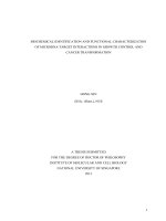
Figure 1(a) shows the vertical PFM amplitude signal from the point where the AFM tip contacts
an individual P(VDF-TrFE) NW during a DC voltage sweep (blue curve for up-poling and red curve
for down-poling) with hysteresis indicative of FE switching/poling. Note that although the curves
are not symmetrical around zero bias, the amplitude values for the different polarizations are relatively similar. This measurement was performed in continuous DC mode, and therefore a typical
V-shape curve is observed due to increased electrostatic cantilever-sample interaction.30 Figures 1(b)
and 1(c) show the vertical PFM signal corresponding to the out-of-plane piezo-response of a NW
before and after the application of ±10 V across 1 µm sections of the NW (b) and thin film (TF) (c).
The color and sign contrast are a clear indication of ferroelectricity in these NWs, and measurements
30 or 45 min after the poling process maintain the trend, e.g., Fig. 1(b) (ii) and (iii) show the same
location imaged 30 min apart after poling treatment. Figure 1(d) shows the uncalibrated lateral PFM
signal amplitude (i) and phase (ii) recorded simultaneously with the corresponding vertical PFM
116106-3
Calahorra et al.
APL Mater. 4, 116106 (2016)
FIG. 1. (a) A PE amplitude hysteresis loop obtained atop a NW; (b) vertical PFM signals in pm/V from a NW subjected
to local poling of ±10 V: (i) before, (ii) immediately after poling, and (iii) 30 min after poling; (c) vertical PFM signals
in pm/V (same scale as in (b)), after local poling of the TF sample; (d) lateral PFM: (i) amplitude and (ii) phase obtained
simultaneously with (c); (e) lateral PFM amplitude from the NW, obtained simultaneously with (b) (ii). The double arrow
indicates the tip orientation during the scan.
signal for TF. Figure 1(e) shows the lateral PFM amplitude from the NW, obtained simultaneously
with Figure 1(b) (ii). The extracted results for the effective piezoelectric coefficient, deff , from the
NW and TF samples, with different tip-velocities during poling, and different times after the poling
are presented in Table I.
Several important observations can be made following these experiments and from the results presented in Table I: (i) the pristine “unpoled” regions of the TF and NW had different deff
values. While the films exhibited values close to zero as expected, the NWs exhibited a non-zero,
down-poled oriented value. This can be attributed to the inherent self-poled nature of the NW, as has
been discussed at length previously.16 (ii) The efficiency of the poling procedure in NWs was found
to be velocity-dependent and asymmetric with regards to up- and down- poling (with down poling
usually stronger). While symmetric poling was achieved in the TF sample, NW poling remained
asymmetric even with a slower scan. (iii) The poled regions in the TF gave rise to distinct lateral
PFM signals that were mostly absent in poled NW regions (appearing only at domain boundaries).
The lateral signals exhibited opposite phases in the oppositely poled regions. (iv) The deff values
obtained from TFs are considerably smaller than from NWs. (v) Some local NW damage resulting
in PE-active residue being present on the passive substrate was only observed during up-poling
of the NWs, as evident by the bright surface contrast around the dark area in Fig. 1(b) (another
example is the circled region in Fig. 3). Generally, the deff values reported here are comparable to
TABLE I. Extracted |d eff | for P(VDF-TrFE) NWs and TFs. Gray tint indicates a measurement on the same location 30 min
later. The voltage was applied to the sample, hence the up- and down-poled orientations.
Sample
TF (100 oC)
TF (60 oC)
NW
NWb
a This
bThe
Tip velocity (µm/s)
2
2
2-3a
1.3
Un-poled [pm/V]
↓ (@ -10 V) (pm/V)
↑ (@ 10 V) (pm/V)
See
∼0
10.1 ± 2.5
9.2 ± 2.3
Fig. 1(c)
∼0
8.8 ± 2.5
6 ± 1.3
∼0
5.5 ± 2.5 (↓)
3.8 ± 1.1
19.6 ± 4.6
5.6 ± 1.2
13.4 ± 5.8
Fig. S5(d)
Fig. 1(b)
7.7 ± 2.2 (↓)
21.6 ± 4.1
15.5 ± 6.2
Fig. 1(b)
6 ± 3.7 (↓)
32.1 ± 3.3
9.8 ± 4.2
5.5 ± 2.9 (↓)
27.1 ± 2.3
9.1 ± 3.5
is an estimated velocity since data were not captured during poling.
measurements were taken 15 and 45 min after poling.
Fig. S4(a)
116106-4
Calahorra et al.
APL Mater. 4, 116106 (2016)
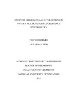
FIG. 2. Displacement of a single NW following a localized poling process. The numbering in the bottom left of the
images indicates the capture sequence. Vertical PFM images (raw data) (a) before poling, (b) after up-poling, and (c) after
down-poling; green and pink dashed squares depict up- and down-poled areas, respectively. Dashed yellow lines show original
NW location; topography of the NW during: (d) up- and (e) down-poling, whereby NW vanishes from the scanning frame.
(f) Vertical PFM cross sections obtained from the NW in (b) and (c) (green and pink). Arrows indicate poled regions on the
NW: black arrows for up-poled regions, notably switching contrast and pink arrows for down-poled regions.
other reports in the literature,27,31 indicating adequate processing. The larger coefficients found for
NWs are also in agreement with previous reports.19
Figure 2 shows a series of AFM images depicting the µm-scale movement of a NW following tip-induced electrical poling. Thermal drift and/or other imaging artifacts were ruled out, as
such movement was absent when the NWs were imaged without a poling field being applied.
Figures 2(a)–2(c) correspondingly show the vertical PFM signal of the NW before any poling
process was undertaken, after an up-poling procedure, and after a subsequent down poling procedure,
designed in a sandwich configuration (see designated poling areas in Fig. 2(a)). Remarkably, the NW
was found to exhibit a ∼2 µm movement, brought about by the down-poling procedure; the position
of the NW prior to any poling is marked by the dashed yellow line. This striking phenomenon was
reproducibly observed only for down-poling procedures over the course of ∼10 poling experiments.
Figures 2(d) and 2(e) show the NW topography during poling, with the sudden movement of the
NW during down-poling captured—as marked by the pink arrow. Figure 2(f) shows two PFM signal
profiles taken along the NWs after the up- and down-poling procedures. Generally, the length of the
poled regions is consistent with the poling procedures; however, two observations are noteworthy:
first, although the up-poling was done across ∼4 µm, the measured PFM value is not uniform, with
a strong response in the lower part of the poled region. This probably resulted from a relatively
fast scanning rate (7 µm/s) used in the up-poling scan. The dip observed towards the bottom end
of the frame could result from double scanning by the poling tip, due to the start of a new frame.
Second, the area which was previously strongly poled in the up direction became down-poled (black
arrow in all sub-figures), although the exact cause for this remains unclear as it is not consistently
observed across measurements. Other examples for NW movement are shown in the supplementary
material (Fig. S6), and in Fig. 3. In order to verify that this is not simply a result of mechanical
movement by the tip, a NW was imaged repeatedly, in order to induce mechanical effects. There
was no corresponding macro-scale movement of the NW observed, only local damage (ripping) was
imaged—see the supplementary material (Fig. S7). This localized movement of the NW relative
to the substrate was also observed optically as shown in the supplementary material, Figure S8.
The section of the NW which moves is only a small fraction of the total length and is mostly
116106-5
Calahorra et al.
APL Mater. 4, 116106 (2016)
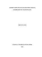
FIG. 3. Effect of poling on localized mechanical properties of a single NW: (a) contact mode topography image of a NW
before poling; (b) (i) topography and (ii) PFM of the same NW following up- (green arrow) and down-poling (pink arrows);
(c) corresponding QNM mode (i) topography and (ii) modulus images from the NW; (d) elastic modulus channel scanning the
up-poled region; (e) line scan obtained from poled area (dashed box) in (d), showing the diminished modulus of the up-poled
region. The red and green circles indicate the same features captured in different scans/channels, verifying the spatial location
of the scans.
restricted to the region where the poling process is undertaken. A possibly related phenomenon has
previously been reported in P(VDF-TrFE) thin films where down-poled domains were found to grow
non-linearly with time as well as voltage.32,33
We now discuss the intrinsic mechanical properties of the poled NWs as measured by QNM.
The experimental procedure was to pole sections of NWs as shown in Fig. 1 and then image the
same areas using QNM. Figure 3 shows a series of SPM images of the same NW, taken before and
after up- and down-poling of separate segments of the NW; the upper sub-figures were taken during
contact mode PFM scanning, while the bottom sub-figures were taken during QNM measurements,
with a different AFM tip. The red (smaller) and green (larger) circles point out the same features on
the substrate that are used as markers to ascertain the location of the features in the QNM measurement relative to the PFM measurement (arrows point to poled regions). Notably, the feature in the
green circle was observed only after the poling process and the residue was left on the substrate as
a result of the up-poling process (similar to what was shown in Fig. 1). This region is located away
from the NW, since the down-poling process resulted in a significant displacement of the NW relative to its original location (where the residue was found). Following the successful location of the
poled regions (Fig. 3(c)), a slow, high-resolution scan (0.1 Hz, 1024 samples/line) was performed
(Fig. 3(d)). A localized reduction of the extracted elastic modulus was observed corresponding to
the poled regions of the NW, as is evident by the change of dominant colors from black-yellow
(on the top and sides of the NW) to green-orange. A line scan taken from that region (Fig. 3(e))
indicated a reduction of 500 MPa in the extracted modulus value. This observation is in agreement
with previous reports of a lower modulus along the poled axis of P(VDF-TrFE),34 although other
reports indicate that the poled orientation has a larger elastic modulus.35 It is important to note that
while the Derjaguin-Muller-Toporov (DMT) model used by the QNM software to extract elastic
moduli is suitable for planar samples but not directly to NWs, the qualitative comparison between
116106-6
Calahorra et al.
APL Mater. 4, 116106 (2016)
the different regions of the same NW is still valid (see the supplementary material, Sec. IV for
further discussion).25
A possible origin of the observed localized electromechanical interaction effects is in the
inherent asymmetries in the chemical and electrical interactions of P(VDF-TrFE) in different polarization states with the substrate, enhanced by the additional mechanical degrees of freedom of the
tip-NW-substrate system, as compared to the plate capacitor configuration, or the tip-TF-substrate
system. Asymmetric effects related to polarization of PVDF based materials, and indeed ferroelectric materials in general, manifest as a difference in coercive voltage of up and down polarizations,
or between subsequent poling steps (imprint effect), and are usually attributed to electrode work
function and surface oxide, trapped interface charge, and film disorder.11,32,36,37 Although critical to
ferroelectric device performance, there is not yet a full understanding of these effects. Of these, we
rule out the effect of electrode surface oxide, as this was shown to be considerably reduced when
using gold electrodes (as in our case).11,37 However, Schottky effect might induce preferential (and
self-) poling to the material due to the differences in work-function (see also the supplementary
material).38,39
A basic distinction between the NW and the TF configurations is the non-clamped nature of
the NW on the substrate, both laterally and relative to the substrate.40,41 The absence of lateral PFM
from the poled regions of the NW, compared to the clear, polarization dependent signal from the
TF sample (Fig. 1 and the supplementary material, Fig. S3), is an interesting manifestation of this.
This result is surprising, considering that P(VDF-TrFE) β-phase crystal structure results in the preference of 60◦ rotations of the horizontal dipole configuration (see Fig. 4).11,28 Therefore some lateral
signal is expected during up- or down-poling, and its absence in the NWs is intriguing. In addition,
the distinct nano-indentation of NWs and TFs also demonstrates this, as shown by finite-element
simulations (see the supplementary material, Fig. S9). If so, this lack of constraint is expected to
allow relaxation of the material to more stable configurations, and indeed we observe changes in the
extracted deff values obtained from the NWs in the range of minutes. The most notable change is in
the value of deff (∼5 pm/V) obtained for slow-scan down-poling, while the corresponding changes
are less prominent in the TF samples. It might also account for the larger values usually measured
(and in this work as well) for NW compared to thin films. When considering a NW section being
poled, the energy needed to pole an equivalent clamped section would likely be higher than the
energy needed to overcome the restriction imposed by the clamped configuration.
The lack of constraints may also explain the increased mechanical freedom of the NW system,
wherein the asymmetries between the two polarization states are more pronounced. As mentioned
above, the tip-NW-substrate is asymmetrical; in addition, the P(VDF-TrFE)/metal interface is inherently asymmetrical, as the molecular layer closest to the metal is different for each polarization and
for the pristine NW. Apart from work function related phenomena, one can consider the molecular nature of the interface. Figure 4 schematically shows the interface in different configurations:
in case of up-poling, the atoms closest to the surface are a uniform layer of fluorine atoms (in
the crystalline regions), while in the down-polarization the closest atoms are a blend of fluorine
and hydrogen atoms; in the case of “side” poling the molecular chains are stacked horizontally,
with the dipole pointing horizontally, and the closest atoms to the metal are again fluorine and
hydrogen. This implies that the chemical interactions as well as the electrical interaction of the
FIG. 4. Schematic illustrations of P(VDF-TrFE) chains: (a) 3D view of a single all-trans chain, showing the different
termination of the fluorine (larger green spheres) and hydrogen (smaller white spheres) edges of the chain; (b) chain side
view, with the (i) lateral and (ii) 60◦ rotated configurations, corresponding to (200) and (110) planes aligned with the surface;
(c) the theoretically unstable configuration of complete up-poled dipoles. (Image prepared with the help of http://molview.
org.)
116106-7
Calahorra et al.
APL Mater. 4, 116106 (2016)
interface molecules and dipoles are different for each configuration. The dipole-substrate interaction
is thus dependent upon the dipole orientation and its distance from the surface, both of which have
been shown to be very different for different polarizations.42–45 As an example, when considering
dipoles perpendicular and parallel to a metallic surface, a single dipole would be more stable in a
perpendicular orientation due to the attraction to its image, while an array of dipoles might be more
stable parallel to the surface due to mutual repulsion of perpendicular dipoles.44 Furthermore, there
could be a change in the preferred orientation of a single dipole (HF molecule in this case) from
perpendicular to parallel, when approaching the surface.45
If so, it is reasonable that the different polarization states have different energies on the gold
substrate; in our case, for down-polarization, considering the higher deff values obtained and the
shorter poling times (higher tip velocity which still enables poling), it appears that this polarization is considerably more stable compared to up-polarization. This observation is in agreement
with the report by Sharma et al. and Kim et al., where down-poled domains were found to grow
more efficiently (with time as well as with voltage), even to an extent of exhibiting a non-linear
increase in radius, after a certain threshold.32,33 Interestingly, when considering single ions (having a much larger interaction with an adjacent metallic surface), density functional theory (DFT)
calculation shows that H+ is considerably more stable compared to F−,45 providing perhaps some
insight into the energy consideration of equivalent layer termination in the case of P(VDF-TrFE).
Dipole-substrate interaction was recently suggested as a driving force for the preferred edge-on,
and increased crystallinity, of Pd-doped PVDF TFs.46 A similar effect has also been reported for
Ag-doped PVDF-TrFE.47
The observation of the pristine sections of the NW exhibiting a consistent down-poled deff value
of about 5-6 pm/V may further indicate that down-polarization is favourable in our system resulting from NW-substrate interaction as discussed above. Alternatively, the NW may possess a net,
non-axial component of polarization which, upon dispersion on the surface, aligns according to the
interface preference. The AAO template related process should not result in an inherent asymmetry,
therefore it is reasonable that the former case is prevalent; however, we cannot currently distinguish
between the two alternatives, and future work will be concerned with this issue. The local damage observed in some of the up-poled regions may then be due to increased mechanical stresses
induced by the presence of conflicting forces in these regions, resulting perhaps in amorphization
or local loss of ferroelectric ordering, and thus the correspondingly reduced deff extracted. This is
also consistent with the observed reduced elastic modulus in this region, as the elastic modulus of
polymers is expected to increase with crystallinity.23,48 The sudden µm-scale movement of the NW
during poling (Fig. 2) could be related to a non-linear response and the instantaneous expansion
of the domain such that mechanical stresses resulting from the switch are released through this
movement, which is otherwise not possible in TF samples.
Recently, Guo and Setter have developed a model28 based on bulk (or volume) dipole-dipole
interactions to explain thickness dependent preferred orientations of P(VDF-TrFE) TFs. By summing up the interaction energies of the horizontal and the 60◦ rotated orientations (Fig. 4(b)), for a
given volume, they point to a crossover of the energies when the thickness of the TF is comparable with the grain size; thus inducing preference of the horizontal orientation for “very” thin
films.28 In contrast to TFs, NWs inherently have similar “width” and “thickness” (and in the case of
∼200 nm NWs can accommodate symmetric grains28), and so the volume model mentioned above
would result in similar contributions of the different orientations to the bulk energy, thus effectively
allowing for other effects, such as surface (or interface) effects, to come into play.
To conclude, we have performed localized poling experiments on single P(VDF-TrFE) NW
and on spin coated TFs of the same composition using an AFM tip. The results indicate significant
distinctions in the electromechanical behavior of NWs and TFs; most notably was the absence
of lateral PFM signal from poled sections of NWs and a strong asymmetry between up- and
down-poling efficiency in the NWs. On a larger scale, we have observed movement of the NW in
exclusive relation to the down-poling procedure. We have subsequently examined, using QNM, the
elastic properties of the poled and un-poled regions of the NWs and found that the up-poled region
became softer following poling.
116106-8
Calahorra et al.
APL Mater. 4, 116106 (2016)
We attribute these observations to the different electronic and chemical surface interactions of
the P(VDF-TrFE) with the substrate and/or ambient, which prevail due to the uniform geometry
of the NW, and the reduced mechanical clamping which otherwise plays a significant role in TF
samples. We believe that these results shed light on the electromechanical interplay in regards to
ferroelectric P(VDF-TrFE) NWs, as well as on fundamental processes in this material that are not
commonly observed when studying TFs.
See the supplementary material for details of the scanning probe microscopy modes used in
this work, material synthesis, calibration procedure and data for PFM and QNM, additional control
experimental data, and computational modelling of local indentation in thin films and nanowires of
P(VDF-TrFE).
S.K.-N. and Y.C. are grateful for financial support from the European Research Council
through an ERC Starting Grant (Grant No. ERC-2014-STG-639526, NANOGEN). R.A.W. thanks
the EPSRC Cambridge NanoDTC, EP/G037221/1, for studentship funding. Q.J. is grateful for
financial support through a Marie Sklodowska Curie Fellowship, H2020-MSCA-IF-2015-702868.
Supporting data for this paper is available at the DSpace@Cambridge data repository (.
org/10.17863/CAM.6215).
1
R. A. Whiter, V. Narayan, and S. Kar-Narayan, “A scalable nanogenerator based on self-poled piezoelectric polymer
nanowires with high energy conversion efficiency,” Adv. Energy Mater. 4(18), 1400519 (2014).
2 D. Kim, S. Hong, D. Li, H. S. Roh, G. Ahn, J. Kim, M. Park, J. Hong, T.-h. Sung, and K. No, “A spring-type piezoelectric
energy harvester,” RSC Adv. 3(10), 3194–3198 (2013).
3 D. J. Li, S. Hong, S. Gu, Y. Choi, S. Nakhmanson, O. Heinonen, D. Karpeev, and K. No, “Polymer piezoelectric energy
harvesters for low wind speed,” Appl. Phys. Lett. 104(1), 012902 (2014).
4 D. Kim, H. S. Roh, Y. Kim, K. No, and S. Hong, “Selective current collecting design for spring-type energy harvesters,”
RSC Adv. 5(14), 10662–10666 (2015).
5 Z. Hu, M. Tian, B. Nysten, and A. M. Jonas, “Regular arrays of highly ordered ferroelectric polymer nanostructures for
non-volatile low-voltage memories,” Nat. Mater. 8(1), 62–67 (2009).
6 L. Persano, C. Dagdeviren, Y. Su, Y. Zhang, S. Girardo, D. Pisignano, Y. Huang, and J. A. Rogers, “High performance piezoelectric devices based on aligned arrays of nanofibers of poly (vinylidenefluoride-co-trifluoroethylene),” Nat. Commun. 4,
1633 (2013).
7 M. Sung, K. Shin, and W. Moon, “A new transduction mechanism for hydrophones employing piezoelectricity and a
field-effect transistor,” Sens. Actuators, A 233, 557–568 (2015).
8 B. B. Tian, J. L. Wang, S. Fusil, Y. Liu, X. L. Zhao, S. Sun, H. Shen, T. Lin, J. L. Sun, C. G. Duan et al., “Tunnel electroresistance through organic ferroelectrics,” Nat. Commun. 7, 11502 (2016).
9 P. Hitscherich, S. Wu, R. Gordan, L.-H. Xie, T. Arinzeh, and E. J. Lee, “The effect of PVDF-TrFE scaffolds on stem cell
derived cardiovascular cells,” Biotechnol. Bioeng. 113(7), 1577–1585 (2016).
10 T. Furukawa, “Ferroelectric properties of vinylidene fluoride copolymers,” Phase Transitions 18(3-4), 143–211 (1989).
11 T. Furukawa, T. Nakajima, and Y. Takahashi, “Factors governing ferroelectric switching characteristics of thin VDF/TrFE
copolymer films,” IEEE Trans. Dielectr. Electr. Insul. 13(5), 1120–1131 (2006).
12 S. Crossley, R. A. Whiter, and S. Kar-Narayan, “Polymer-based nanopiezoelectric generators for energy harvesting applications,” Mater. Sci. Technol. 30(13), 1613–1624 (2014).
13 S. Crossley and S. Kar-Narayan, “Energy harvesting performance of piezoelectric ceramic and polymer nanowires,” Nanotechnology 26(34), 344001 (2015).
14 D. Li, J. Xiong, Y. Guo, and G. Li, “Ferroelectric phase transition effect of doping trifluoroethylene monomer in poly
(vinylidene fluoride),” J. Appl. Phys. 115(20), 204106 (2014).
15 M. Bohlén and K. Bolton, “Conformational studies of poly (vinylidene fluoride), poly (trifluoroethylene) and poly (vinylidene fluoride-co-trifluoroethylene) using density functional theory,” Phys. Chem. Chem. Phys. 16(25), 12929–12939 (2014).
16 R. A. Whiter, Y. Calahorra, C. Ou, and S. Kar-Narayan, “Observation of confinement-induced self-poling effects in ferroelectric polymer nanowires grown by template wetting,” Macromol. Mater. Eng. 301, 1016 (2016).
17 V. Cauda, G. Canavese, and S. Stassi, “Nanostructured piezoelectric polymers,” J. Appl. Polym. Sci. 132(13), 41667 (2015).
18 D. Kim, S. Hong, J. Hong, Y.-Y. Choi, J. Kim, M. Park, T.-h. Sung, and K. No, “Fabrication of vertically aligned ferroelectric
polyvinylidene fluoride mesoscale rod arrays,” J. Appl. Polym. Sci. 130(6), 3842–3848 (2013).
19 Y. Wu, Q. Gu, G. Ding, F. Tong, Z. Hu, and A. M. Jonas, “Confinement induced preferential orientation of crystals and
enhancement of properties in ferroelectric polymer nanowires,” ACS Macro Lett. 2(6), 535–538 (2013).
20 V. Cauda, S. Stassi, K. Bejtka, and G. Canavese, “Nanoconfinement: An effective way to enhance PVDF piezoelectric
properties,” ACS Appl. Mater. Interfaces 5(13), 6430–6437 (2013).
21 V. Sencadas, C. Ribeiro, I. K. Bdikin, A. L. Kholkin, and S. Lanceros-Mendez, “Local piezoelectric response of single poly
(vinylidene fluoride) electrospun fibers,” Phys. Status Solidi A 209(12), 2605–2609 (2012).
22 M. Baniasadi, J. Huang, Z. Xu, S. Moreno, X. Yang, J. Chang, M. A. Quevedo-Lopez, M. Naraghi, and M. Minary-Jolandan,
“High-performance coils and yarns of polymeric piezoelectric nanofibers,” ACS Appl. Mater. Interfaces 7(9), 5358–5366
(2015).
23 M. Baniasadi, Z. Xu, S. Hong, M. Naraghi, and M. Minary-Jolandan, “Thermo-electromechanical behavior of piezoelectric
nanofibers,” ACS Appl. Mater. Interfaces 8(4), 2540–2551 (2016).
116106-9
24
Calahorra et al.
APL Mater. 4, 116106 (2016)
J. A. Christman, H. Maiwa, S.-H. Kim, A. I. Kingon, and R. J. Nemanich, “Piezoelectric measurements with atomic force
microscopy,” in MRS Proceedings (Cambridge University Press, 1998), Vol. 541, p. 617.
25 B. Pittenger, N. Erina, and C. Su, Quantitative Mechanical Property Mapping at the Nanoscale with PeakForce QNM
(Bruker, 2012).
26 J. Song, H. Lu, S. Li, L. Tan, A. Gruverman, and S. Ducharme, “Fabrication of ferroelectric polymer nanostructures on
flexible substrates by soft-mold reverse nanoimprint lithography,” Nanotechnology 27(1), 015302 (2015).
27 Y.-Y. Choi, P. Sharma, C. Phatak, D. J. Gosztola, Y. Liu, J. Lee, B. Lee, J. Li, A. Gruverman, S. Ducharme et al., “Enhancement of local piezoresponse in polymer ferroelectrics via nanoscale control of microstructure,” ACS Nano 9(2), 1809–1819
(2015).
28 D. Guo and N. Setter, “Impact of confinement-induced cooperative molecular orientation change on the ferroelectric size
effect in ultrathin p (vdf-trfe) films,” Macromolecules 46(5), 1883–1889 (2013).
29 M. Mai, S. Ke, P. Lin, and X. Zeng, “Intrinsic and extrinsic effects on the ferroelectric switching of thin poly(vinylidene
fluoride/trifluoroethylene) copolymer films,” APL Mater. 4(4), 046107 (2016).
30 S. Hong, J. Woo, H. Shin, J. U. Jeon, Y. E. Pak, E. L. Colla, N. Setter, E. Kim, and K. No, “Principle of ferroelectric domain
imaging using atomic force microscope,” J. Appl. Phys. 89(2), 1377–1386 (2001).
31 Y.-Y. Choi, J. Hong, S. Hong, H. Song, D.-S. Cheong, and K. No, “Nanoscale piezoresponse of 70 nm poly (vinylidene
fluoride-trifluoro-ethylene) films annealed at different temperatures,” Phys. Status Solidi RRL 4(3-4), 94–96 (2010).
32 P. Sharma, T. Nakajima, S. Okamura, and A. Gruverman, “Effect of disorder potential on domain switching behavior in
polymer ferroelectric films,” Nanotechnology 24(1), 015706 (2012).
33 Y. Kim, W. Kim, H. Choi, S. Hong, H. Ko, H. Lee, and K. No, “Nanoscale domain growth dynamics of ferroelectric poly
(vinylidene fluoride-co-trifluoroethylene) thin films,” Appl. Phys. Lett. 96(1), 012908 (2010).
34 Y. Roh, V. V. Varadan, and V. K. Varadan, “Characterization of all the elastic, dielectric, and piezoelectric constants of
uniaxially oriented poled PVDF films,” IEEE Trans. Ultrasonics, Ferroelectrics, Freq. Control 49(6), 836–847 (2002).
35 L. Otani, J.-I. Mawatari, A. Yoshihara, and H. Ohigashi, “Elastic anisotropy of single crystalline P [VDF/TrFE] copolymer
films with 75/25 mol ratio,” Jpn. J. Appl. Phys., Part 1 39(5S), 2922 (2000).
36 M. Grossmann, O. Lohse, D. Bolten, U. Boettger, T. Schneller, and R. Waser, “The interface screening model as origin of
imprint in PbZrx Ti1−x O3 thin films. I. Dopant, illumination, and bias dependence,” J. Appl. Phys. 92(5), 2680–2687 (2002).
37 C. Lew and M. O. Thompson, “Characterizing trapped charge dynamics in imprinted poly (vinylidene fluoridetrifluoroethylene) ferroelectric thin films using the fast ramp thermally stimulated current technique,” J. Appl. Phys. 105(5),
054112 (2009).
38 A. L. Kholkin, K. G. Brooks, D. V. Taylor, S. Hiboux, and N. Setter, “Self-polarization effect in pb (Zr, Ti) O thin films,”
3
Integr. Ferroelectr. 22(1-4), 525–533 (1998).
39 Y.-Y. Choi, S. Tong, S. Ducharme, A. Roelofs, and S. Hong, “Charge collection kinetics on ferroelectric polymer surface
using charge gradient microscopy,” Sci. Rep. 6, 25087 (2016).
40 A. V. Bune, C. Zhu, S. Ducharme, L. M. Blinov, V. M. Fridkin, S. P. Palto, N. G. Petukhova, and S. G. Yudin, “Piezoelectric
and pyroelectric properties of ferroelectric Langmuir–Blodgett polymer films,” J. Appl. Phys. 85(11), 7869–7873 (1999).
41 A. Safari and E. K. Akdogan, Piezoelectric and Acoustic Materials for Transducer Applications (Springer Science & Business Media, 2008).
42 S. Holmström and S. Holloway, “The interaction of a dipole with a metal surface,” Surf. Sci. Lett. 173(2-3), L647–L654
(1986).
43 B. L. Maschhoff and J. P. Cowin, “Corrected electrostatic model for dipoles adsorbed on a metal surface,” J. Chem. Phys.
101(9), 8138–8151 (1994).
44 A. Kokalj, “Electrostatic model for treating long-range lateral interactions between polar molecules adsorbed on metal
surfaces,” Phys. Rev. B 84(4), 045418 (2011).
45 A. M. Gabovich, V. M. Gun’ko, V. E. Klymenko, and A. I. Voitenko, “Role of dipole image forces in molecular adsorption,”
Eur. Phys. J. B 85(8), 1–11 (2012).
46 D. Mandal, K. J. Kim, and J. S. Lee, “Simple synthesis of palladium nanoparticles, β-phase formation, and the control of
chain and dipole orientations in palladium-doped poly (vinylidene fluoride) thin films,” Langmuir 28(28), 10310–10317
(2012).
47 H. Paik, Y.-Y. Choi, S. Hong, and K. No, “Effect of Ag nanoparticle concentration on the electrical and ferroelectric properties
of Ag/P (VDF-TrFE) composite films,” Sci. Rep. 5, 13209 (2015).
48 L. Holliday, “The stiffness of polymers in relation to their structure,” in Structure and Properties of Oriented Polymers
(Springer, 1975), pp. 242–263.