the induction machine handbook chuong (9)
Bạn đang xem bản rút gọn của tài liệu. Xem và tải ngay bản đầy đủ của tài liệu tại đây (623.68 KB, 48 trang )
Author: Ion Boldea, S.A.Nasar………… ………
Chapter 9
SKIN AND ON – LOAD SATURATION EFFECTS
9.1. INTRODUCTION
So far we have considered that resistances, leakage and magnetization
inductances are invariable with load.
In reality, the magnetization current I
m
varies only slightly from no-load to
full load (from zero slip to rated slip S
n
≈ 0.01 – 0.06), so the magnetization
inductance L
1m
varies little in such conditions.
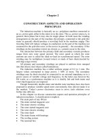
However, as the slip increases toward standstill, the stator current increases
up to (5.5 – 6.5) times rated current at stall (S = 1).
In the same time, as the slip increases, even with constant resistances and
leakage inductances, the magnetization current I
m
decreases.
So the magnetization current decreases while the stator current increases
when the slip increases (Figure 9.1).
0.2
0.4
0.6
0.8
1.0
1
2
3
4
5
6
I
I
s
sn
L I
V
ω
1m
1sn
sn
l =
m
0.1
0.2
0.3
I
I
m
sn
l
I
m
m
S
a.)
S
R’
r
L
sl
L’
rl
0
1.0
0
b.
)
l
m
,
/I
sn
Figure 9.1 Stator I
s
/I
sn
and magnetization I
m
current, magnetization inductance (l
m
) in p.u. a.),
leakage inductance and rotor resistance versus slip b.)
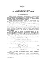
When the rotor (stator) current increases with slip, the leakage magnetic
field path in iron tends to saturate. With open slots on stator, this phenomenon is
limited, but, with semiopen or semiclosed slots, the slot leakage flux path
saturates the tooth tops both in the stator and rotor (Figure 9.2) above (2−3)
times rated current.
Also, the differential leakage inductance which is related to main flux path
is affected by the tooth top saturation caused by the circumpherential flux
produced by slot leakage flux lines (Figure 9.2). As the space harmonics flux
paths are contained within τ/π from the airgap, only the teeth saturation affects
them.
© 2002 by CRC Press LLC
Author: Ion Boldea, S.A.Nasar………… ………
A A A
xxx
q=3
A A A
xxxx
Figure 9.2 Slot leakage flux paths Figure 9.3 Zig-zag flux lines
Further on, for large values of stator (and rotor) currents, the zig-zag flux
becomes important and contributes notably to teeth top magnetic saturation in
addition to slot leakage flux contribution.
Rotor slot skewing is also known to produce variable main flux path
saturation along the stack length together with the magnetization current.
However the flux densities from the two contributions are phase shifted by an
angle which varies and increases towards 90
0
at standstill. The skewing
contribution to the main flux path saturation increases with slip and dominates
the picture for S > S
k
as the magnetization flux density, in fact, decreases with
slip so that at standstill it is usually 55 to 65% of its rated value.
A few remarks are in order.
• The magnetization saturation level in the core decreases with slip, such that
at standstill only 55 – 65% of rated airgap flux remains.
• The slot leakage flux tends to increase with slip (current) and saturates the
tooth top unless the slots are open.
• Zig – zag circumpherential flux and skewing accentuate the magnetic
saturation of teeth top and of entire main flux path, respectively, for high
currents (above 2 to 3 times rated current).
• The differential leakage inductance is also reduced when stator (and rotor)
current increases as slot, zig-zag, and skewing leakage flux effects increase.
• As the stator (rotor) current increases the main (magnetising) inductance
and leakage inductances are simultaneously influenced by saturation. So
leakage and main path saturation are not independent of each other. This is
why we use the term: on-load saturation.
As expected, accounting for these complex phenomena simultaneously is
not an easy tractable mathematical endeavour. Finite element or even refined
analytical methods may be suitable. Such methods are presented in this chapter
after more crude approximations ready for preliminary design are given.
Besides magnetic saturation, skin (frequency) effect influences both the
resistances and slot leakage inductances. Again, a simultaneous treatment of
both aspects may be practically done only through FEM.
© 2002 by CRC Press LLC
Author: Ion Boldea, S.A.Nasar………… ………
On the other hand, if slot leakage saturation occurs only on the teeth top and
the teeth, additional saturation due to skewing does not influence the flux lines
distribution within the slot, the two phenomena can be treated separately.
Experience shows that such an approximation is feasible. Skin effect is
treated separately for the slot body occupied by a conductor. Its influence on
equivalent resistance and slot body leakage geometrical permeance is accounted
for by two correction coefficients, K
R
and K
X
. The slot neck geometry is
corrected for leakage saturation.
Motor geometry and
initial (constant)
parameters for
equivalent circuit
S=K S
00
.
K=1,2,
I
s
I’
r
I
m
γ
( ’)II
sr
Procedure to calculate
equivalent parameters
of equivalent circuit
as influenced by skin
and on - load
saturation effects
Calculate new values of
I ,I’ ,
as I (j), I’ (j), (j)
γ
γ
s
r
s
r
Main flux
path
nonlinear
model
motor
geometry
error check
|I (j)-I (j-1)|
|I (j)|
<
ε
ss
s
s
|I’(j)-I’(j-1)|
|I’(j)|
<
ε
rr
r
r
| (j)- (j-1)|
| (j)|
γγ
γ
<
ε
γ
I (j+1)=I (j)+K (I (j)-I (j-1))
ssuss
I’(j+1)=I’(j)+K (I’(j)-I’(j-1))
rrurr
γγ γγ
(j+1)= (j)+K ( (j)- (j-1))
u
I (S), I’(S), (S), cos (S)
T (S), I (S), L (S), L (S)
L’ (S), R’(S)
γϕ
sr
em sl m
rl r
I
m
,
L (I )
1m m
No
Yes
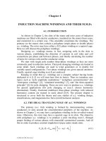
Figure 9.4 Iterative algorithm to calculate IM performance and parameters as influenced by skin and
on-load saturation effects.
Finally, the on load saturation effects are treated iteratively for given slip
values to find, from the equivalent circuit with variable parameters, the steady
state performance. The above approach may be summarized as in Figure 9.4.
The procedure starts with the equivalent circuit with constant parameters
and calculates initial values of stator and rotor currents I
s
, I
r
′
and their phase
© 2002 by CRC Press LLC
Author: Ion Boldea, S.A.Nasar………… ………
shift angle γ. Now that we described the whole picture, let us return to its
different facets and start with skin effect.
9.2. THE SKIN EFFECT
As already mentioned, skin effects are related to the flux and current density
distribution in a conductor (or a group of conductors) flowed by a.c. currents
and surrounded by a magnetic core with some airgaps.
Easy to use analytical solutions have been found essentially only for
rectangular slots, but adaptation for related shapes has also become traditional.
More general slots with notable skin effect (of general shape) have been so
far treated through equivalent multiple circuits after slicing the conductor(s) in
slots in a few elements.
A refined slicing of conductor into many sections may be solved only
numerically, but within a short computation time. Finally, FEM may also be
used to account for skin effect. First, we will summarize some standard results
for rectangular slots.
9.2.1. Single conductor in rectangular slot
Rectangular slots are typical for the stator of large IMs and for wound
rotors of the same motors. Trapezoidal (and rounded) slots are typical for low
power motors.
The case of a single conductor in slot is (Figure 9.5) typical to single
(standard) cage rotors and is commonplace in the literature. The main results are
given here.
The correction coefficients for resistance and slot leakage inductance K
R
and K
X
are
()
()
()
()
()
()
dc
sls
ac
sls
X
dc
ac
R
L
L
2cos2cosh
2sin2sinh
2
3
K ;
R
R
2cos2cosh
2sin2sinh
K
=
ξ−ξ
ξ−ξ
ξ
==
ξ−ξ
ξ+ξ
ξ=
(9.1)
with
tyconductivi electrical ;
b
b
2
S
1
;
h
h
Al
s
cAl01
AlAl
s
s
−σ
σµω
=
δ
=β
δ
=β=ξ
(9.2)
The slip S signifies that in this case the rotor (or secondary) of the IM is
considered.
Figure 9.5 depicts K
R
and K
x
as functions of ξ, which, in fact, represents the
ratio between the conductor height and the field penetration depth δ
Al
in the
conductor for given frequency Sω
1
. With one conductor in the slot, the skin
effects, as reflected in K
R
and K
x
, increase with the slot (conductor) height, h
s
,
for given slip frequency Sω
1
.
© 2002 by CRC Press LLC
Author: Ion Boldea, S.A.Nasar………… ………
b
s
b
c
x
h
s
0
slot leakage
field H(x)
current density
J(x)
a.)
1
234
5
0.2
0.4
0.6
0.8
1.0
ξ
K
()
ξ
R
ξ
3
2ξ
K
()
ξ
x
b.)
1
2
3
4
5
Figure 9.5 Rectangular slot
a.) slot field (H(x)) and current density (J(x)) distributions
b.) resistance K
R
and slot leakage inductance K
X
skin effect correction factors
This rotor resistance increase, accompanied by slot leakage inductance
(reactance) decrease, leads to both a lower starting current and a higher starting
torque.
This is how the deep bar cage rotor has evolved. To increase further the
skin effects, and thus increase starting torque for even lower starting current
(I
start
= (4.5−5)I
rated
), the double cage rotor was introduced by the turn of this
century already by Dolivo – Dobrovolski and later by Boucherot.
The advent of power electronics, however, has led to low frequency starts
and thus, up to peak torque at start, may be obtained with (2.5
−
3) times rated
current. Skin effect in this case is not needed. Reducing skin effect in large
induction motors with cage rotors lead to particular slot shapes adequate for
variable frequency supply.
9.2.2. Multiple conductors in rectangular slots: series connection
Multiple conductors are placed in the stator slots, or in the rotor slots of
wound rotors (Figure 9.6).
b
s
n
I
u
I
p
b
h
Figure 9.6 Multiple conductors in rectangular slots
According to Emde and R.Richter [1,2] who continued the classic work of
Field [3], the resistance correction coefficient K
RP
for the p
th
layer in slot (Figure
9.6) with current I
p
, when total current below p
th
layer is I
u
, is
© 2002 by CRC Press LLC
Author: Ion Boldea, S.A.Nasar………… ………
()
(
)
()
ξψ
+γ
+ξϕ=
2
p
puu
RP
I
IcosII
K
(9.3)
()
()
()
()
()
()
ξ+ξ
ξ−ξ
ξ=ξψ
ξ−ξ
ξ+ξ
ξ=ξϕ
coscosh
sinsinh
2 ;
2cos2cosh
2sin2sinh
(9.4)
s
Al01
nn
b
nb
2
S
;h
σµω
=ββ=ξ
There are n conductors in each layer and γ is the angle between I
p
and I
u
phasors.
In two-layer windings with chorded coils, there are slots where the current
in all conductors is the same and some in which two phases are located and thus
the currents are different (or there is a phase shift γ = 60
0
).
For the case of γ = 0 with I
u
= I
p
(p - 1) Equation (9.3) becomes
()
(
)
()
ξψ−+ξϕ= ppK
2
RP
(9.5)
This shows that the skin effect is not the same in all layers. The average
value of K
RP
for m layers,
() () ()
1
3
1m
pK
m
1
K
2
m
1
RPRm
>ξψ
−
+ξϕ==
∑
(9.6)
Based on [4], for γ ≠ 0 in (9.6) (m
2
−1)/3 is replaced by
()
3
1
24
cos35m
2
−
γ+
(9.6’)
A similar expression is obtained for the slot-body leakage inductance
correction K
x
[4].
()
()
()
1
m
'1m
'K
2
2
xm
<
ξψ−
+ξϕ=
(9.7)
()
(
)
()
ξ−ξ
ξ−ξ
ξ
=ξϕ
2cos2cosh
2sin2sinh
2
3
'
(9.8)
()
(
)
()
ξ+ξξ
ξ+ξ
=ξψ
coscosh
sinsinh
'
(9.9)
Please note that the first terms in K
Rm
and K
xm
are identical to K
R
and K
x
of
(9.1) valid for a single conductor in slot. As expected, K
Rm
and K
xm
degenerate
into K
R
and K
x
for one layer (conductor) per slot. The helping functions
ϕ, ψ, ϕ′, ψ′
are quite general (Figure 9.7).
© 2002 by CRC Press LLC
Author: Ion Boldea, S.A.Nasar………… ………
For a given slot geometry, increasing the number of conductor layers in slot
reduces their height h = h
s
/m and thus reduces ξ, which ultimately reduces ψ(ξ)
in (9.6). On the other hand, increasing the number of layers, the second term in
(9.6) tends to increase.
5
4
3
2
1
1
2
3
0.5
ϕ
ϕ
’
ψ
’
12
2.5
ξ
0.0
ψ
’
ψ
ϕ
ϕ
’
K
Rm
m
1
1.5
m
(critical)
K
h
s
-given
S
ω
1
-given
Figure 9.7 Helping functions ϕ, Ψ, ϕ′, Ψ′ versus ξ
It is thus evident that there is a critical conductor height h
c
for which the
resistance correction coefficient is minimum. Reducing the conductor height
below h
c
does not produce a smaller K
Rm
.
In large power or in high speed (frequency), small/medium power machines
this problem of critical conductor height is of great importance to minimize the
additional (a.c.) losses in the windings.
A value of K
Rm
≈ (1.1 – 1.2) is in most cases, acceptable. At power grid
frequency (50 – 60 Hz), the stator skin effect resistance correction coefficient is
very small (close to 1.0) as long as power is smaller than a few hundred kW.
Inverter-fed IMs, however, show high frequency time harmonics for which
K
Rm
may be notable and has to be accounted for.
Example 9.1. Derivation of resistance and reactance corrections
Let us calculate the magnetic field H(x) and current density J(x) in the slot of an
IM with m identical conductors (layers) in series making a single layer winding.
Solution
To solve the problem we use the field equation in complex numbers for the
slot space where only along slot depth (OX) the magnetic field and current
density vary.
()
()
xH
b
b
j
x
xH
Co0
s
2
2
σωµ=
∂
∂
(9.10)
The solution of (9.10) is
()
() ()
2b
b
;eCeCxH
01
s
xj1
2
xj1
1
σµω
=β+=
β++β+−
(9.11)
© 2002 by CRC Press LLC
Author: Ion Boldea, S.A.Nasar………… ………
1
2
3
h
b
b
s
0
x
stator current
I
s
P
x
x -n
p
p
H(x)
a.)
x
b.)
2
1
I
s
I
s
J(x)
J(x)
current
density
Figure 9.8 Stator slot with single coil with m layers (conductors in series) a.) and
two conductors in series b.)
The boundary conditions are
(
)
()
()
hx x;1pIbhxH
ph x;x x;pIbxH
pssp
ppssp
−=−=⋅−
===⋅
(9.12)
From (9.11) and (9.12), we get the expressions of the constants C
1
and C
2
()
[]
()
() ()
()
[]
()
[]
()
() ()
()
[]
hxj1xj1
s
s
2
hxj1xj1
s
s
1
pp
pp
pee1p
hj1sinhb2
I
C
pee1p
hj1sinhb2
I
C
−β+−β+−
−β+β+
+−−
β+
=
−−
β+
=
(9.13)
The current density J
(x) is
()
()
()
() ()
[]
xj1
2
xj1
1
ss
eCeCj1
b
b
x
xH
b
b
xJ
β+β+−
−+β−=
∂
∂
−=
(9.14)
For m = 2 conductors in series per slot, the current density distribution
(9.14) is as shown qualitatively in Figure 9.8.
The active and reactive powers in the p
th
conductor S
p
is calculated using
the Poyting vector [4].
−
σ
=+=
=−=
pp
xx
*
hxx
*
Co
s
.c.a.c.a
.c.a
2
H
2
J
2
H
2
J
Lb
jQPS
(9.15)
Denoting by R
pa
and X
pa
the a.c. resistance and reactance of conductor p, we
may write
2
sacac
2
sacac
IXQ IRP ==
(9.16)
© 2002 by CRC Press LLC
Author: Ion Boldea, S.A.Nasar………… ………
The d.c. resistance R
dc
and reactance X
dc
of conductor p,
lengthstack -L ;
h3
Lb
X ;
hb
L1
R
s
0dc
Co
dc
ωµ=
σ
=
(9.17)
The ratios between a.c. and d.c. parameters K
Rp
and K
xp
are
dc
ac
xp
dc
ac
Rp
X
X
K ;
R
R
K ==
(9.18)
Making use of (9.11) and (9.14) leads to the expressions of K
Rp
and K
xp
represented by (9.5) and (9.6).
9.2.3. Multiple conductors in slot: parallel connection
Conductors are connected in parallel to handle the phase current, In such a
case, besides the skin effect correction K
Rm
, as described in paragraph 9.3.2 for
series connection, circulating currents will flow between them. Additional losses
are produced this way.
When multiple round conductors in parallel are used, their diameter is less
than 2.5(3) mm and thus, at least for 50(60) Hz machines, the skin effect may be
neglected altogether. In contrast, for medium and large power machines, with
rectangular shape conductors (Figure 9.9), the skin effect influence has at least
to be verified. In this case also, the circulating current influence is to be
considered.
A simplified solution to this problem [5] is obtained by neglecting, for the
time being, the skin effect of individual conductors (layers), that is by assuming
a linear leakage flux density distribution along the slot height. Also the inter-
turn insulation thickness is neglected.
At the junction between elementary conductors (strands), the average a.c.
magnetic flux density B
ave
≈ B
m
/4 (Figure 9.11a). The a.c. flux through the cross
section of a strand Φ
ac
is
stackaveac
hlB=Φ
(9.19)
The d.c. resistance of a strand R
dc
is
bh
l
1
RR
turn
Co
dcac
σ
=≈
(9.20)
Now the voltage induced in a strand turn E
ac
is
acac
E Φω=
(9.21)
So the current in a strand I
st
, with the leakage inductance of the strand
neglected, is:
acacst
R/EI =
(9.22)
© 2002 by CRC Press LLC
Author: Ion Boldea, S.A.Nasar………… ………
b
b
s
h
1a
1b
2a
2b
B
B /2
m
B /4
m
a.)
1a
1b
2a
2b
B /2
m
m
B
m
1a
1b
1c
2a
2b
2c
B /2
m
1c
1b
1a
2c
2b
2a
b.)
Figure 9.9 Slot leakage flux density for coil sides: two turn coils
a.) two elementary conductors in parallel (strands) b.) three elementary conductors in parallel
The loss in a strand P
strand
is
bh
l
1
lhB
R
E
P
turn
Co
2
stack
2
ave
22
ac
ac
2
strand
σ
ω
==
(9.23)
As seen from Figure 9.9a, the average flux density B
ave
is
()
s
phasecoil0
m
ave
b4
cos1In
4
B
B
γ+µ
==
(9.24)
I
phase
is the phase current and γ is the angle between the currents in the upper
and lower coils. Also, n
coil
is the number of turns per coil (in our case n
coil
=
2,3).
The usual d.c. loss in a strand with current (two vertical strands / coil) is
2
phase
dcdc
2
I
RP
=
(9.25)
We may translate the circulating new effect into a resistance additional
coefficient, K
Rad
.
© 2002 by CRC Press LLC
Author: Ion Boldea, S.A.Nasar………… ………
()
4
cos1n
l
l
b
hb
P
P
K
2
2
coil
2
turn
stack
2
s
42
2
Co
2
0
2
dc
strand
Rad
γ+
σµω=≈
(9.26)
Expression (9.26) is strictly valid for two vertical strands in parallel.
However as B
ave
seems to be the same for other number of strands/turn,
Equation (9.26) should be valid in general.
Adding the skin effect coefficient K
Rm
as already defined to the one due to
circulating current between elementary conductors in parallel, we get the total
skin effect coefficient K
R||
.
Rad
turn
stack
Rm||R
K
l
l
KK +=
(9.26’)
Even with large power IMs, K
R||
should be less than 1.25 to 1.3 with K
Rad
<
0.1 for a proper design.
Example 9.2.
Skin effect in multiple vertical conductors in slot
Let us consider a rather large induction motor with 2 coils, each made of 4
elementary conductors in series, respectively, and, of two turns, each of them
made of two vertical strands (conductors in parallel) per slot in the stator. The
size of the elementary conductor is h⋅b = 5⋅20 [mm⋅mm] and the slot width b
s
=
22 mm; the insulation thickness along slot height is neglected. The frequency f
1
= 60 Hz. Let us determine the skin effect in the stack zone for the two cases, if
l
stack
/l
turn
= 0.5.
Solution
As the elementary conductor is the same in both cases, the first skin effect
resistance correction coefficient K
Rm
may be computed first from (9.6) with ξ
from (9.4),
5466.010532.109
m32.109
22
20
108.12
10256.1602
b
b
2
8mmh ;h
3
1
8
6
s
Co01
n
n
=⋅⋅=ξ
=
⋅⋅
⋅⋅π
=
σµω
=β
=β=ξ
−
−
−
−
The helping functions ϕ(ξ) and ψ(ξ) are (from (9.7)): ϕ(ξ) = 1.015, ψ(ξ) =
0.04. Now with m = 8 layers in slot K
Rm
(9.6) is
99.104.0
3
18
015.1K
2
Rm
=
−
+=
Now, for the parallel conductors (2 in parallel), the additional resistance
correction coefficient K
Rad
(9.26) for circulating currents is
© 2002 by CRC Press LLC
Author: Ion Boldea, S.A.Nasar………… ………
()
()
()
()
()
!3918.0
4
1125.0105
22
20
108.1
1
60210256.1K
2
22
4
3
2
2
8
2
2
6
Rad
=
+⋅⋅⋅⋅
⋅
⋅
⋅
π⋅=
−
−
−
The coefficient K
Rad
refers to the whole conductor (turn) length, that is, it
includes the end-turn part of it. K
Rm
is too large, to be practical.
9.2.4. The skin effect in the end turns
There is a part of stator and rotor windings that is located outside the
lamination stack, mainly in air: the end turns or endrings.
The skin effect for conductors in air is less pronounced than in their
portions in slots.
As the machine power or frequency increases, this kind of skin effect is to
be considered. In Reference [6] the resistance correction coefficient K
R
for a
single round conductor (d
Co
) is also a function of β in the form (Figure 9.10).
2
d
Co01
Co
σµω
=ξ
(9.27)
1234567
1.0
1.5
2.0
K
R
ξ
8
16
20 b h (cm )
11
2
f =50Hz
1
a.) b.)
1.1
1.2
1.3
b
h
1
1
h /b =1
11
2
5
Figure 9.10 Skin effect correction factor K
R
for a round conductor in air:
a.) circular b.) rectangular
On the other hand, a rectangular conductor in air [7] presents the resistance
correction coefficient (Figure 9.10) based on the assumption that there are
magnetic field lines that follow the conductor periphery.
In general, there are m layers of round or rectangular conductors on top of
each other (Figure 9.11).
© 2002 by CRC Press LLC
Author: Ion Boldea, S.A.Nasar………… ………
B
H
a.)
b.)
H/2
b =B+1.2H
s
h
1
Figure 9.11 Four layer coil in air a.) and its upper part placed in an equivalent (fictious) slot
Now the value of ξ is
conductorsr rectangulafor
H2.1B
B
2
h
conductors roundfor
H2.1B
B
2
d
01
1
01
Co
+
σµω
=ξ
+
σµω
=ξ
(9.28)
As the skin effect is to be reduced, ξ should be made smaller than 1.0 by
design. And, in this case, for rectangular conductors displaced in m layers [2],
the correction coefficient K
Rme
is
(
)
4
2
Rme
36
8.0m
1K ξ
−
+=
(9.29)
For a bundle of Z round conductors [24] K
Rme
is
()( )
24
Rme
Hz50/fcm/dZ005.01K ⋅⋅+=
(9.29’)
The skin effect in the endrings of rotors may be treated as a single
rectangular conductor in air. For small induction machines, however, the skin
effect in the endrings may be neglected. In large IMs, a more complete solution
is needed. This aspect will be treated later in this chapter.
For the IM in example 9.2, with m = 4, ξ = 0.5466, the skin effect in the end
turns K
Rme
(9.29) is
!0377.15466.0
36
8.04
1K
2
2
Rme
=
−
+=
As expected, K
Rme
<< K
Rm
corresponding to the conductors in slot. The total
skin effect resistance correction coefficient K
Rt
is
()
Rad
coil
stackcoilRmestackRm
Rt
K
l
llKlK
K
+
−+
=
(9.30)
For the case of example 9.2,
© 2002 by CRC Press LLC
Author: Ion Boldea, S.A.Nasar………… ………
949.13918.05572.13918.0
5.1
5.1
1
10377.199.1
K
Rt
=+=+
−+
=
for 2 conductors in parallel and K
Rt
= 1.5572, for all conductors in series.
9.3. SKIN EFFECTS BY THE MULTILAYER APPROACH
For slots of more general shape, adopted to exploit the beneficial effects of
rotor cages, a simplified solution is obtained by dividing the rotor bar into n
layers of height h
t
and width b
j
(Figure 9.12). The method originates in [1].
For the p
th
layer Faraday’s law yields
p
1
1p
1p
p
p
jSIRIR Φ∆ω−=−
+
+
(9.31)
n
p
b
p
b
j
j
h
t
h
1
1
h
t
∆Φ
p
I
b
I
1
I
2
I
p
I
n
zero resistance
ring
Figure 9.12 More general shape rotor bars
∑
=
+
+
µ
=∆Φ
σ
=
σ
=
p
1j
j
p
tstack0
p
t1p
stack
Al
1p
tp
stack
Al
p
I
b
hl
;
hb
l
1
R ;
hb
l
1
R
(9.32)
R
p
and R
p+1
represent the resistances of p
th
and (p+1)
th
layer and L
p
the
inductance of p
th
layer.
p
tstack0
p
b
hl
L
µ
=
(9.33)
With (9.33), Equation (9.31) becomes
∑
=
++
+
ω
+=
p
1j
j
1p
p1
p
1p
p
1p
I
R
LS
jI
R
R
I
(9.34)
Let us consider p = 1,2 in (9.34)
1
2
11
1
2
1
2
I
R
LS
jI
R
R
I
ω
+=
(9.35)
© 2002 by CRC Press LLC
Author: Ion Boldea, S.A.Nasar………… ………
()
21
3
21
2
3
2
3
II
R
LS
jI
R
R
I
+
ω
+=
(9.36)
If we assign a value to I
1
in relation to total current I
b
, say,
()
n
I
I
b
initial
1
=
, (9.37)
we may use Equations (9.34) through (9.36) to determine the current in all
layers. Finally,
()
∑
=
=
n
1j
jb
I' I
(9.38)
As expected, I
b
and I
b
′ will be different. Consequently, the currents in all
layers will be multiplied by I
b
/I
b
′ to obtain their real values. On the other hand,
Equations (9.35) – (9.36) lead to the equivalent circuit in Figure 9.12.
Once the layer currents I
1
, … I
n
are known, the total losses in the bar are
∑
=
=
n
1j
j
2
jac
RIP
(9.39)
I
1
V
b1
I
2
V
b2
I
3
V
b3
R
1
R
2
R
3
I
1
I
1
I
2
+
jS L
ω
11
jS L
ω
12
I
n
V
bn
R
n
1n-1
jS L
ω
1n
jS L
ω
I =
b
Σ
j
=1
n
I
j
V
bar
Figure 9.13 Equivalent circuit for skin effect evaluation
In a similar manner, the magnetic energy in the slot W
mac
is
2
j
1
k
n
1j
jmac
IL
2
1
W
∑∑
=
=
(9.40)
The d.c. power loss in the slot (for given total bar current) P
dc
is
jt
bar
b
jdc
j
2
jdcdc
bh
A
'I
I ;RIP ==
∑
(9.41)
© 2002 by CRC Press LLC
Author: Ion Boldea, S.A.Nasar………… ………
Also the d.c. magnetic energy in the slot
2
j
1
kdc
n
1j
jmdc
IL
2
1
W
∑∑
=
=
(9.42)
Now the skin effect resistance and inductance correction coefficients K
R
, K
x
are
∑
∑
=
=
==
n
1j
j
2
jdc
n
1j
j
2
j
dc
ac
R
RI
RI
P
P
K
(9.43)
2
j
1k
kdc
n
1j
j
2
j
1k
k
n
1j
j
x
IL
IL
K
∑∑
∑∑
==
==
=
(9.44)
Example 9.3.
Let us consider a deep bar of the shape in Figure 9.12 with the
dimensions as in Figure 9.14.
Let us divide the bar into only 6 layers, each 5 mm high (h
t
= 5 mm) and
calculate the skin effects for S = 1 and f
1
= 60 Hz.
1
2
3
4
5
6
10
5
15
20mm
14mm
8mm
b =b =14mm
56
stack length
l =1m
stack
b =8mm
b =b =b =20mm
123
4
Figure 9.14 Deep bar geometry
Solution
From Figure 9.14, the layer resistances and inductances are (9.32 – 9.33).
Ω⋅=
⋅⋅⋅⋅
=
σ
===
−
−−
3
337
t1
stack
Al
321
10333.0
1051020
1
103
1
hb
l
1
RRR
© 2002 by CRC Press LLC
Author: Ion Boldea, S.A.Nasar………… ………
Ω⋅=
⋅⋅⋅⋅
=
σ
=
−
−−
3
337
t4
stack
Al
4
10833.0
105108
1
103
1
hb
l
1
R
Ω⋅=
⋅⋅⋅⋅
=
σ
==
−
−−
3
337
t5
stack
Al
65
10476.0
1051014
1
103
1
hb
l
1
RR
From (9.33)
H10314.0
020.0
005.0
110256.1
b
hl
LLL
66
1
tstack0
321
−−
⋅=⋅⋅⋅=
µ
===
H10785.0
008.0
005.0
10256.1
b
hl
L
66
5
tstack0
4
−−
⋅=⋅⋅=
µ
=
H1044857.0
014.0
005.0
10256.1
b
hl
LL
66
5
tstack0
65
−−
⋅=⋅⋅=
µ
==
Let us now consider that the bar current is I
b
= 3600A and I
1
= I
b
/n = I
b
/6 =
600A. Now I
2
(in the second layer from slot bottom) is
A18.213j600600
10333.0
10314.0
6021j600I
R
LS
jI
R
R
I
3
6
1
2
11
1
2
1
2
+=⋅
⋅
⋅
⋅π⋅⋅+=
ω
+=
−
−
A74.634I
2
=
()
()
A640j25.52418.213j600600
10333.0
10314.0
6021j
18.213j600II
R
LS
jI
R
R
I
3
6
21
3
21
2
3
2
3
+=++⋅
⋅
⋅
⋅π⋅⋅+
++=+
ω
+=
−
−
A3.827I
3
=
()
()
()
A2.490j5.55
640j52418.213j600600
10833.0
10314.0
6021j
26.426j25.524
10833.0
10333.0
III
R
LS
jI
R
R
I
3
6
3
3
321
4
31
3
4
3
4
+=
++++⋅
⋅
⋅
⋅π⋅⋅+
++
⋅
⋅
=++
ω
+=
−
−
−
−
A27.493I
4
=
© 2002 by CRC Press LLC
Author: Ion Boldea, S.A.Nasar………… ………
()
()
()
A4.2030j088.712
1342j75.1779
104485.0
10785.0
6021j
2.490j5.55
10476.0
10833.0
IIII
R
LS
jI
R
R
I
3
6
3
3
4321
5
41
4
5
4
5
+−=
+⋅
⋅
⋅
⋅π⋅⋅+
++
⋅
⋅
=+++
ω
+=
−
−
−
−
A2.2151I
5
=
()
()
()
A4.2389j75.1735
853j25.17244.2030j088.712
10476.0
1074857.0
6021j
4.2030j088.712
10476.0
10476.0
IIIII
R
LS
jI
R
R
I
3
6
3
3
54321
6
51
5
6
5
6
+−=
+++−⋅
⋅
⋅
⋅π⋅⋅+
++−
⋅
⋅
=
=++++
ω
+=
−
−
−
−
A31.2953I
6
=
Now the total current
A4.4419j75.2447
2389j75.17354.2030j088.712IIIIII'I
654321b
+−=
=+−+−=+++++=
A5050'I
b
≈
The a.c. power in the bar is
()
()
W68.7044636068.202482
31.29552.215110476.027.49310833.0
30.82774.63660010333.0RIP
22323
2223
n
1j
j
2
jac
=++=
=+⋅+⋅⋅+
+++⋅==
−−
−
=
∑
The d.c. current distribution in the 6 layer is uniform, therefore
()
A08.1052
20.155.810.14
5.205050
hb
A
'I
III
t1
bar
b
dc3dc2dc1
=
++
⋅
====
A83.420
480
5.85050
hb
A
'I
I
t4
bar
b
dc4
=
⋅
==
© 2002 by CRC Press LLC
Author: Ion Boldea, S.A.Nasar………… ………
A458.736
480
5.145050
hb
A
'I
II
t5
bar
b
dc6dc5
=
⋅
===
W81.1768458.736210476.083.42010833.0
08.1052310333.0RIP
2323
23
n
1j
j
2
jdcdc
=⋅⋅⋅+⋅⋅+
+⋅⋅⋅==
−−
−
=
∑
and the skin effect resistance correction factor K
R
is
!9827.3
81.1768
68.7044
P
P
K
dc
ac
R
===
The magnetic energy ratio K
x
is
B
A
K
x
=
(
)
2
654321
5
2
54321
5
2
321
4
2
321
2
21
2
1
1
IIIIIILIIIIIL
IIILIIIIIILA
+++++++++++
+++++++++=
()( )
[
]
()()
2
b5
2
6b5
2
dc4dc3dc2dc14
2
dc3dc2dc1
2
dc2dc1
2
dc11
'ILI'ILIIIIL
IIIIIILB
+−+++++
++++++=
(
)
()
62626
626626226
10050.5100554.31044857.0
10229.210785.0109237.110217.160010314.0A
+⋅+
+⋅+++⋅=
−
−−
(
)
()
62626626
6262626
1005.5103128.41044857.010576.310785.0
10156.310104.210052.110314.0B
+⋅+⋅+
+++⋅=
−−
−
!613.0
685.34
267.21
K
x
==
The inductance coefficient refers only to the slot body (filled with
conductor) and not to the slot neck, if any.
A few remarks are in order.
• The distribution of current in the various layers is nonuniform when the
skin effect occurs.
• Not only the amplitude, but the phase angle of bar current in various layers
varies due to skin effect (Figure 9.14).
• At S = 1 (f
1
= 60 Hz) most of the current occurs in the upper part of the slot.
© 2002 by CRC Press LLC
Author: Ion Boldea, S.A.Nasar………… ………
• The equivalent circuit model can be easily put into computer form once the
layers geometry–h
t
(height) and b
j
(width)–are given. For various practical
slots special subroutines may provide b
j
, h
t
when the number of layers is
given.
• To treat a double cage by this method, we have only to consider zero the
current in the empty slot layers between the upper and lower cage (Figure
9.15).
I’
b
I
6
I
5
I
4
I
3
I
2
I
1
Figure 9.14 Layer currents and the bar current with skin effect
empty layers
Figure 9.15 Treating skin effect with equivalent circuit (or multilayer) method
Now that both K
R
and K
x
are known, the bar resistance and slot body
leakage geometrical specific permeance λ
sbody
is modified to account for skin
effect.
(
)
(
)
x
dc
sbody
ac
sbody
Kλ=λ
(9.45)
From d.c. magnetic energy W
mdc
(9.42), we write
()
dc
sbodystack0
2
b
mdc
dc
l
'I
W
2
1
L λµ==
(9.46)
© 2002 by CRC Press LLC
Author: Ion Boldea, S.A.Nasar………… ………
The slot neck geometrical specific permeance is still to be added to account
for the respective slot leakage flux. This slot neck geometrical specific
permeance is to be corrected for leakage flux saturation discussed later in this
chapter.
9.4. SKIN EFFECT IN THE END RINGS VIA THE MULTILAYER
APPROACH
As the end rings are placed in air, although rather close to the motor
laminated stack, the skin effect in them is routinely neglected. However, there
are applications where the value of slip goes above unity (S = up to 3.0 in
standard elevator drives) or the slip frequency is large as in high frequency
(high speed) motors to be started at rated frequency (400 Hz in avionics).
For such cases, the multilayer approach may be extended to end rings. To
do so we introduce radial and circumpherential layers in the end rings (Figure
9.16) as shown in Reference [7].
a.)
R (j)
c
R (j-1)
c
R (j)
r
R (j-1)
r
I (j)
r
I (
j
)e
r
-j
2p
N
π
r
I (j)
c
I (j-1)
c
I (j)
b
b.)
R (j)
c
R (j-1)
c
h
l
j-layer
j-1-layer
j-2
bar contour
h /2
l
r
j
r
j-1
c.)
1
R (j)
r
R (j-1)
r
Figure 9.16 Bar-end ring transition
a.) slot cross – section b.) radial and circumpherential layer end ring currents
c.) geometry of radial and circumpherential end ring layers
In all layers, the current density is considered uniform. It means that their
radial dimension has to be less than the depth of field penetration in aluminum.
© 2002 by CRC Press LLC
Author: Ion Boldea, S.A.Nasar………… ………
The currents in neighboring slots are considered phase-shifted by 2πp
1
/N
r
radians (N
r
–number of rotor slots).
The relationship between bar and end ring layer currents (Figure 9.16) is
)j(c)j(r
N
p2
j
)j(r)1j(r)j(b
IIeIII
r
1
+=++
π
+
(9.47)
0
50
100
150
1.2
1.4
1.6
1.8
2.0
2.2
16 poles
K
Rr
Frequency (Hz)
Figure 9.17 End ring skin effect resistance coefficient K
Rr
)j(r)j(r)1j(c)1j(c
N
p2
j
)j(r)j(r)j(c)j(c
IRIReIRIR
r
1
+=+
−−
π
−
(9.48)
The circumpherential extension of the radial layer r
j
is assigned a value at
start. Now if we add the equations for the bar layer currents, we may solve the
system of equations. As long as the radial currents increase, γ
j
is increased in the
next iteration cycle until sufficient convergence is met. Some results, after [2],
are given in Figure 9.17.
As the slot total height is rather large (above 25 mm), the end ring skin
effect is rather large, especially for rotor frequencies above 50(60) Hz. In fact, a
notable part of this resistance rise is due to the radial ring currents which tend to
distribute the bar currents, gathered toward the slot opening, into most of end
ring cross section.
9.5. THE DOUBLE CAGE BEHAVES LIKE A DEEP BAR CAGE
In some applications, very high starting torque–T
start
/T
rated
≥ 2.0–is required.
In such cases, a double cage is used. It has been proved that it behaves like a
deep bar cage, but it produces even higher starting torque at lower starting
current. For the case when skin effect can be neglected in both cages, let us
consider a double cage as configured in Figure 9.18. [8]
© 2002 by CRC Press LLC
Author: Ion Boldea, S.A.Nasar………… ………
a
s
a
w
h
4
h
s
h
h
w
a
φ
is
φ
iw
φ
e
φ
w
a
4
R
r
jS (L +L ( ))
ωφ
1ring ee
Z =R (S )+jX ( )
ω
S
ω
be be be
11
R
bs
R
bw
jS L
ω
1bs
jS L
ω
1bw
jS L
ω
1ml
Figure 9.18 Double cage rectangular-shape geometry a.) and equivalent circuit b.)
The equivalent single bar circuit is given in Figure 9.18b. For the common
ring of the two cages
R
r
= R
ring
, R
bs
= R
bs upper bar
, R
bw
= R
bw lower bar
(9.49)
For separate rings
R
r
= 0, R
bs
= R
bs
+ R
e
rings
, R
bw
= R
bw
+ R
e
ringw
(9.50)
The ring segments are included into the bar resistance after approximate
reduction as shown in Chapter 6. The value of L
ring
is the common ring
inductance or is zero for separate rings. Also for both cases, L
e
(
Φ
e
) refers to the
slot neck flux.
()
4
4
stack0ee
a
h
lL
µ=Φ
(9.51)
We may add into L
e
the differential leakage inductance of the rotor.
The start (upper) and work (lower) cage inductances L
bs
and L
bw
include the
end ring inductances only for separate rings. Otherwise, the bar inductances are
++µ=
µ=
s
s
w
w
stack0bw
s
s
stack0bs
a
h
a
h
a3
h
lL
a3
h
lL
(9.52)
© 2002 by CRC Press LLC
Author: Ion Boldea, S.A.Nasar………… ………
There is also a flux common to the two cages represented by the flux in the
starting cage. [3]
s
s
stack0ml
a2
h
lL
µ=
(9.53)
In general, L
ml
is neglected though it is not a problem to consider in solving
the equivalent circuit in Figure 9.18. It is evident (Figure 9.18a) that the starting
(upper) cage has a large resistance (R
bs
) and a small slot leakage inductance L
bs
,
while for the working cage the opposite is true.
Consequently, at high slip frequency, the rotor current resides mainly in the
upper (starting) cage while, at low slip frequency, the current flows mainly into
the working (lower) cage. Thus both R
be
and X
be
vary with slip frequency as
they do in a deep bar single cage (Figure 9.19).
R (S )
ω
1be
X (S )
ω
1be
S
ω
ω
1
1
Figure 9.19 Equivalent parameters of double cage versus slip frequency
9.6. LEAKAGE FLUX PATH SATURATION–A SIMPLIFIED
APPROACH
Leakage flux path saturation occurs mainly in the slot necks zone for
semiclosed slots for currents above 2 to 3 times rated current or in the rotor slot
iron bridges for closed slots even well below the rated current (Figure 9.20).
Consequently,
()
()
()
br
bor
or
s
i
sr0
r
orsr
oror
s
i
ss0
s
osss
osos
b
'a
N
g2D
;
a
a'a
N
D
;
a
a'a
µ
µ
=
−π
=τµ
µ
−τ
+=
π
=τµ
µ
−τ
+=
(9.54)
The slot neck geometrical permeances will be changed to: a′
os
/h
os
, a′
or
/h
or
, or
a′
or
/h
or
dependent on stator (rotor) current.
© 2002 by CRC Press LLC
Author: Ion Boldea, S.A.Nasar………… ………
x x
τ Γ
ss s
H
ts
H
os
a
os
h
os
h
or
a
or
Γ
r
τ
b
or
I
I
s
rated
>(2-3)
I
I
s
rated
>(0.1-0.2)
B
H
B
ts
(
r
)
H
ts
(
r
)
sr
B (H )
br tr
Figure 9.20 Leakage flux path saturation conditions
With n
s
the number of turns (conductors) per slot, and I
s
and I
b
the stator
and rotor currents, the Ampere’s law on Γ
s
, Γ
r
trajectories in Figure 9.20 yields
()
()
tb
tb
brbortr
or0trtrrborororsrtr
os0tstssssosososssts
H
B
;2IbH
HBH ;2IaHaH
HBH ;2InaHaH
=µ=
µ==µ≈+−τ
µ==µ≈+−τ
(9.55)
The relationship between the equivalent rotor current I
r
′ (reduced to the
stator) and I
b
is (Chapter 8)
r
s
1wsr
r
1ws1
rb
N
N
Kn'I
N
Kqnp6
'II ==
(9.56)
N
s
–number of stator slots; K
w1
–stator winding factor.
When the stator and rotor currents I
s
and I
r
′ are assigned pertinent values,
iteratively, using the lamination magnetization curves, Equations (9.55) may be
solved (Figure 9.20) to find the iron permeabilities of teeth tops or of closed
rotor slot bridges. Finally, from (9.54), the corrected slot openings are found.
With these values, the stator and rotor parameters (resistances and leakage
inductances) as influenced by the skin effect (in the slot body zone) and by the
leakage saturation (in the slot neck permeance) are recalculated. Continuing
with these values, from the equivalent circuit, new values of stator and rotor
currents I
s
, I
r
′ are calculated for given stator and voltage, frequency and slip.
The iteration cycles continue until sufficient convergence is obtained for
stator current.
© 2002 by CRC Press LLC