The Centrifugal Pump (Bơm ly tâm) docx
Bạn đang xem bản rút gọn của tài liệu. Xem và tải ngay bản đầy đủ của tài liệu tại đây (5.89 MB, 128 trang )
The Centrifugal Pump
GRUNDFOS
RESEARCH AND TECHNOLOGY
The Centrifugal Pump
5
All rights reserved.
Mechanical, electronic, photographic or other reproduction or copying from this book or parts
of it are according to the present Danish copyright law not allowed without written permission
from or agreement with GRUNDFOS Management A/S.
GRUNDFOS Management A/S cannot be held responsible for the correctness of the information
given in the book. Usage of information is at your own responsibility.
6
Preface
In the Department of Structural and Fluid Mechanics
we are happy to present the first English edition of the
book: ’The Centrifugal Pump’. We have written the book
because we want to share our knowledge of pump hy-
draulics, pump design and the basic pump terms which
we use in our daily work.
’The Centrifugal Pump’ is primarily meant as an inter-
nal book and is aimed at technicians who work with
development and construction of pump components.
Furthermore, the book aims at our future colleagues,
students at universities and engineering colleges, who
can use the book as a reference and source of inspira-
tion in their studies. Our intention has been to write
an introductory book that gives an overview of the hy-
draulic components in the pump and at the same time
enables technicians to see how changes in construc-
tion and operation influence the pump performance.
In chapter 1, we introduce the principle of the centrifu-
gal pump as well as its hydraulic components, and we
list the dierent types of pumps produced by Grundfos.
Chapter 2 describes how to read and understand the
pump performance based on the curves for head, pow-
er, eciency and NPSH.
In chapter 3 you can read about how to adjust the
pump’s performance when it is in operation in a system.
The theoretical basis for energy conversion in a centrifu-
gal pump is introduced in chapter 4, and we go through
how anity rules are used for scaling the performance
of pump impellers. In chapter 5, we describe the dier-
ent types of losses which occur in the pump, and how
the losses aect flow, head and power consumption. In
the book’s last chapter, chapter 6, we go trough the test
types which Grundfos continuously carries out on both
assembled pumps and pump components to ensure
that the pump has the desired performance.
The entire department has been involved in the devel-
opment of the book. Through a longer period of time we
have discussed the idea, the contents and the structure
and collected source material. The framework of the
Danish book was made after some intensive working
days at ‘Himmelbjerget’. The result of the department’s
engagement and eort through several years is the book
which you are holding.
We hope that you will find ‘The Centrifugal Pump’ use-
ful, and that you will use it as a book of reference in you
daily work.
Enjoy!
Christian Brix Jacobsen
Department Head, Structural and Fluid Mechanics, R&T
7
Contents
Chapter 1. Introduction to Centrifugal Pumps 11
1.1 Principle of centrifugal pumps 12
1.2 The pump’s hydraulic components 13
1.2.1 Inlet flange and inlet 14
1.2.2 Impeller 15
1.2.3 Coupling and drive 17
1.2.4 Impeller seal 18
1.2.5 Cavities and axial bearing 19
1.2.6 Volute casing, diuser and
outlet flange 21
1.2.7 Return channel and outer sleeve 23
1.3 Pump types and systems 24
1.3.1 The UP pump 25
1.3.2 The TP pump 25
1.3.3 The NB pump 25
1.3.4 The MQ pump 25
1.3.5 The SP pump 26
1.3.6 The CR pump 26
1.3.7 The MTA pump 26
1.3.8 The SE pump 27
1.3.9 The SEG pump 27
1.4 Summary 27
Chapter 2. Performance curves 29
2.1 Standard curves 30
2.2 Pressure 32
2.3 Absolute and relative pressure 33
2.4 Head 34
2.5 Dierential pressure across the pump 35
2.5.1 Total pressure dierence 35
2.5.2 Static pressure dierence 35
2.5.3 Dynamic pressure dierence 35
2.5.4 Geodetic pressure dierence 36
2.6 Energy equation for an ideal flow 37
2.7 Power 38
2.7.1 Speed 38
2.8 Hydraulic power 38
2.9 Eciency 39
2.10 NPSH, Net Positive Suction Head 40
2.11 Axial thrust 44
2.12 Radial thrust 44
2.13 Summary 45
Chapter 3. Pumps operating in systems 47
3.1 Single pump in a system 49
3.2 Pumps operated in parallel 50
3.3 Pumps operated in series 51
3.4 Regulation of pumps 51
3.4.1 Throttle regulation 52
3.4.2 Regulation with bypass valve 52
3.4.3 Start/stop regulation 53
3.4.4 Regulation of speed 53
3.5 Annual energy consumption 56
3.6 Energy eciency index (EEI) 57
3.7 Summary 58
Chapter 4. Pump theory 59
4.1 Velocity triangles 60
4.1.1 Inlet 62
4.1.2 Outlet 63
4.2 Euler’s pump equation 64
4.3 Blade shape and pump curve 66
8
4.4 Usage of Euler’s pump equation
67
4.5 Anity rules 68
4.5.1 Derivation of anity rules 70
4.6 Pre-rotation 72
4.7 Slip 73
4.8 The pump’s specific speed 74
4.9 Summary 75
Chapter 5. Pump losses 77
5.1 Loss types 78
5.2 Mechanical losses 80
5.2.1 Bearing loss and shaft seal loss 80
5.3 Hydraulic losses 80
5.3.1 Flow friction 81
5.3.2 Mixing loss at
cross-section expansion 86
5.3.3 Mixing loss at
cross-section reduction 87
5.3.4 Recirculation loss 89
5.3.5 Incidence loss 90
5.3.6 Disc friction 91
5.3.7 Leakage 92
5.4 Loss distribution as function of
specific speed 95
5.5 Summary 95
Chapter 6. Pumps tests 97
6.1 Test types 98
6.2 Measuring pump performance 99
6.2.1 Flow 100
6.2.2 Pressure 100
6.2.3 Temperature 101
6.2.4 Calculation of head 102
6.2.5 General calculation of head 103
6.2.6 Power consumption 104
6.2.7 Rotational speed 104
6.3 Measurement of the pump’s NPSH 105
6.3.1 NPSH
3%
test by lowering the
inlet pressure 106
6.3.2 NPSH
3%
test by increasing the flow 107
6.3.3 Test beds 107
6.3.4 Water quality 108
6.3.5 Vapour pressure and density 108
6.3.6 Reference plane 108
6.3.7 Barometric pressure 109
6.3.8 Calculation of NPSH
A
and determination
of NPSH
3%
109
6.4 Measurement of force 109
6.4.1 Measuring system 110
6.4.2 Execution of force measurement 111
6.5 Uncertainty in measurement of performance 111
6.5.1 Standard demands for uncertainties 111
6.5.2 Overall uncertainty 112
6.5.3 Test bed uncertainty 112
6.6 Summary 112
Appendix 113
A. Units 114
B. Control of test results 117
Bibliography 122
Standards 123
Index 124
Substance values for water 131
List of Symbols 132
9
10
Chapter 1
Introduction to
centrifugal pumps
1.1 Principle of the centrifugal pump
1.2 Hydraulic components
1.3 Pump types and systems
1.4 Summary
Outlet Impeller Inlet
1212
Outlet Impeller Inlet
Direction of rotation
1. Introduction to Centrifugal Pumps
1. Introduction to Centrifugal Pumps
In this chapter, we introduce the components in the centrifugal pump and
a range of the pump types produced by Grundfos. This chapter provides the
reader with a basic understanding of the principles of the centrifugal pump
and pump terminology.
The centrifugal pump is the most used pump type in the world. The principle
is simple, well-described and thoroughly tested, and the pump is robust, ef-
fective and relatively inexpensive to produce. There is a wide range of vari-
ations based on the principle of the centrifugal pump and consisting of the
same basic hydraulic parts. The majority of pumps produced by Grundfos
are centrifugal pumps.
1.1 Principle of the centrifugal pump
An increase in the fluid pressure from the pump inlet to its outlet is cre-
ated when the pump is in operation. This pressure dierence drives the fluid
through the system or plant.
The centrifugal pump creates an increase in pressure by transferring me-
chanical energy from the motor to the fluid through the rotating impeller.
The fluid flows from the inlet to the impeller centre and out along its blades.
The centrifugal force hereby increases the fluid velocity and consequently
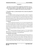
also the kinetic energy is transformed to pressure. Figure 1.1 shows an ex-
ample of the fluid path through the centrifugal pump.
Figure 1.1: Fluid path through
the centrifugal pump.
Impeller
blade
1313
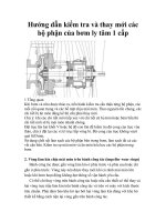
1.2 Hydraulic components
The principles of the hydraulic components are common for most centrifu-
gal pumps. The hydraulic components are the parts in contact with the fluid.
Figure 1.2 shows the hydraulic components in a single-stage inline pump.
The subsequent sections describe the components from the inlet flange to
the outlet flange.
Figure 1.2: Hydraulic
components.
Motor
Diuser
Outlet flange
Cavity above impeller
Cavity below impeller
Impeller seal
Inlet flange
Volute
Inlet
Shaft
Coupling
Pump housing Impeller
Shaft seal
Impeller Inlet
1414
1. Introduction to Centrifugal Pumps
1.2.1 Inlet flange and inlet
The pump is connected to the piping system through its
inlet and outlet flanges. The design of the flanges depends
on the pump application. Some pump types have no inlet
flange because the inlet is not mounted on a pipe but sub-
merged directly in the fluid.
The inlet guides the fluid to the impeller eye. The design of
the inlet depends on the pump type. The four most com-
mon types of inlets are inline, endsuction, doublesuction
and inlet for submersible pumps, see figure 1.3.
Inline pumps are constructed to be mounted on a straight
pipe – hence the name inline. The inlet section leads the
fluid into the impeller eye.
Endsuction pumps have a very short and straight inlet sec-
tion because the impeller eye is placed in continuation of
the inlet flange.
The impeller in doublesuction pumps has two impeller eyes.
The inlet splits in two and leads the fluid from the inlet
flange to both impeller eyes. This design minimises the axial
force, see section 1.2.5.
In submersible pumps, the motor is often placed below the
hydraulic parts with the inlet placed in the mid section of
the pump, see figure 1.3. The design prevents hydraulic los-
ses related to leading the fluid along the motor. In addition,
the motor is cooled due to submersion in the fluid.
Figure 1.3: Inlet for inline, endsuction, doublesuction and submersible pump.
Inline pump Endsuction pump Doublesuction pump Submersible pump
Impeller Inlet
Impeller Inlet
Impeller Inlet
1515
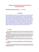
Figure 1.4: Velocity distribution in inlet.
Hub plate Hub
Trailing edge
Shroud plate
Leading edge
Impeller channel
(blue area)
Impeller blade
The impeller’s direction of
rotation
Tangential direction
Radial direction
Axial direction
The impeller’s direction of rotation
Figure 1.5: The impeller components, definitions of directions and flow relatively to the impeller.
The design of the inlet aims at creating a uniform velocity profile into the
impeller since this leads to the best performance. Figure 1.4 shows an example of
the velocity distribution at dierent cross-sections in the inlet.
1.2.2 Impeller
The blades of the rotating impeller transfer energy to the fluid there by
increasing pressure and velocity. The fluid is sucked into the impeller at the
impeller eye and flows through the impeller channels formed by the blades
between the shroud and hub, see figure 1.5.
The design of the impeller depends on the requirements for pressure, flow
and application. The impeller is the primary component determining the
pump performance. Pumps variants are often created only by modifying
the impeller.
1616
1. Introduction to Centrifugal Pumps
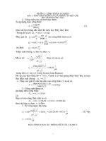
The impeller’s ability to increase pressure and create flow depends mainly
on whether the fluid runs radially or axially through the impeller,
see figure 1.6.
In a radial impeller, there is a significant dierence between the inlet
diameter and the outlet diameter and also between the outlet diameter
and the outlet width, which is the channel height at the impeller exit. In
this construction, the centrifugal forces result in high pressure and low
flow. Relatively low pressure and high flow are, on the contrary, found in an
axial impeller with a no change in radial direction and large outlet width.
Semiaxial impellers are used when a trade-o between pressure rise and flow
is required.
The impeller has a number of impeller blades. The number mainly depends
on the desired performance and noise constraints as well as the amount and
size of solid particles in the fluid. Impellers with 5-10 channels has proven to
give the best eciency and is used for fluid without solid particles. One, two
or three channel impellers are used for fluids with particles such as waste-
water. The leading edge of such impellers is designed to minimise the risk
of particles blocking the impeller. One, two and three channel impellers can
handle particles of a certain size passing through the impeller. Figure 1.7
shows a one channel pump.
Impellers without a shroud are called open impellers. Open impellers are
used where it is necessary to clean the impeller and where there is risk of
blocking. A vortex pump with an open impeller is used in waste water ap-
plication. In this type of pump, the impeller creates a flow resembling the
vortex in a tornado, see figure 1.8. The vortex pump has a low eciency
compared to pumps with a shroud and impeller seal.
After the basic shape of the impeller has been decided, the design of the
impeller is a question of finding a compromise between friction loss and loss
as a concequence of non uniform velocity profiles. Generally, uniform velocity
profiles can be achieved by extending the impeller blades but this results in
increased wall friction.
Figure 1.6: Radial, semiaxial and
axial impeller.
Figure 1.8: Vortex pump.
Radial impeller Semiaxial impeller Axial impeller
Figure 1.7: One channel pump.
1717
1.2.3 Coupling and drive
The impeller is usually driven by an electric motor. The coupling between motor
and hydraulics is a weak point because it is dicult to seal a rotating shaft. In
connection with the coupling, distinction is made between two types of pumps:
Dry-runner pumps and canned rotor type pump. The advantage of the dry-runner
pump compared to the canned rotor type pump is the use of standardized motors.
The disadvantage is the sealing between the motor and impeller.
In the dry runner pump the motor and the fluid are separated either by a shaft
seal, a separation with long shaft or a magnetic coupling.
In a pump with a shaft seal, the fluid and the motor are separated by seal rings, see
figure 1.9. Mechanical shaft seals are maintenance-free and have a smaller leakage
than stung boxes with compressed packing material. The lifetime of mechanical
shaft seals depends on liquid, pressure and temperature.
If motor and fluid are separated by a long shaft, then the two parts will not get
in contact then the shaft seal can be left out, see figure 1.10. This solution has
limited mounting options because the motor must be placed higher than the
hydraulic parts and the fluid surface in the system. Furthermore the solution
results in a lower eciency because of the leak flow through the clearance be-
tween the shaft and the pump housing and because of the friction between the
fluid and the shaft.
Figure 1.9: Dry-runner with shaft seal.
Motor Shaft seal
Figure 1.10: Dry-runner with long shaft.
Exterior magnets on
the motor shaft
Inner magnets on
the impeller shaft
Rotor can
Motor cup
Motor
Motor shaft
Motor cup
Rotor can
Impeller shaft
Inner magnets
Exterior magnets
Figure 1.11: Dry-runner with magnet drive.
Motor
Long shaft
Hydraulics
Water level
1818
InletOutlet Leak flow Gap
In pumps with a magnetic drive, the motor and the fluid are separated by
a non-magnetizable rotor can which eliminates the problem of sealing a
rotating shaft. On this type of pump, the impeller shaft has a line of fixed
magnets called the inner magnets. The motor shaft ends in a cup where the
outer magnets are mounted on the inside of the cup, see figure 1.11. The
rotor can is fixed in the pump housing between the impeller shaft and the
cup. The impeller shaft and the motor shaft rotate, and the two parts are
connected through the magnets. The main advantage of this design is that
the pump is hermitically sealed but the coupling is expensive to produce.
This type of sealing is therefore only used when it is required that the pump
is hermetically sealed.
In pumps with a rotor can, the rotor and impeller are separated from the
motor stator. As shown in figure 1.12, the rotor is surrounded by the fluid
which lubricates the bearings and cools the motor. The fluid around the ro-
tor results in friction between rotor and rotor can which reduces the pump
eciency.
1.2.4 Impeller seal
A leak flow will occur in the gap between the rotating impeller and stationary
pump housing when the pump is operating. The rate of leak flow depends
mainly on the design of the gap and the impeller pressure rise. The leak flow
returns to the impeller eye through the gap, see figure 1.13. Thus, the impel-
ler has to pump both the leak flow and the fluid through the pump from the
inlet flange to the outlet flange. To minimise leak flow, an impeller seal is
mounted.
The impeller seal comes in various designs and material combinations. The
seal is typically turned directly in the pump housing or made as retrofitted
rings. Impeller seals can also be made with floating seal rings. Furthermore,
there are a range of sealings with rubber rings in particular well-suited for
handling fluids with abrasive particles such as sand.
1. Introduction to Centrifugal Pumps
Figure 1.12: Canned rotor type pump.
Impeller seal
Figure 1.13: Leak flow through the gap.
Fluid
Rotor
Stator
Rotor can
Outlet
Impeller
Inlet
Bearings
1919
Primary flow
Achieving an optimal balance between leakage and friction is an essential
goal when designing an impeller seal. A small gap limits the leak flow but
increases the friction and risk of drag and noise. A small gap also increases
requirements to machining precision and assembling resulting in higher
production costs. To achieve optimal balance between leakage and friction,
the pump type and size must be taken into consideration.
1.2.5 Cavities and axial bearing
The volume of the cavities depends on the design of the impeller and the
pump housing, and they aect the flow around the impeller and the pump’s
ability to handle sand and air.
The impeller rotation creates two types of flows in the cavities: Primary
flows and secondary flows. Primary flows are vorticies rotating with the
impeller in the cavities above and below the impeller, see figure 1.14.
Secondary flows are substantially weaker than the primary flows.
Primary and secondary flows influence the pressure distribution on the
outside of the impeller hub and shroud aecting the axial thrust. The axial
thrust is the sum of all forces in the axial direction arising due to the pres-
sure condition in the pump. The main force contribution comes from the
rise in pressure caused by the impeller. The impeller eye is aected by the
inlet pressure while the outer surfaces of the hub and shroud are aected
by the outlet pressure, see figure 1.15. The end of the shaft is exposed to the
atmospheric pressure while the other end is aected by the system pres-
sure. The pressure is increasing from the center of the shaft and outwards.
Figure 1.14: Primary and secondary flows
in the cavities.
Cavity above impeller Cavity below impeller
Secondary flow
2020
The axial bearing absorbs the entire axial thrust and is therefore exposed to
the forces aecting the impeller.
The impeller must be axially balanced if it is not possible to absorb the entire
axial thrust in the axial bearing. There are several possibilities of reducing
the thrust on the shaft and thereby balance the axial bearing. All axial
balancing methods result in hydraulic losses.
One approach to balance the axial forces is to make small holes in the hub
plate, see figure 1.16. The leak flow through the holes influences the flow
in the cavities above the impeller and thereby reduces the axial force but it
results in leakage.
Another approach to reduce the axial thrust is to combine balancing holes
with an impeller seal on the hub plate, see figure 1.17. This reduces the pres-
sure in the cavity between the shaft and the impeller seal and a better bal-
ance can be achieved. The impeller seal causes extra friction but smaller
leak flow through the balancing holes compared to the solution without the
impeller seal.
A third method of balancing the axial forces is to mount blades on the back
of the impeller, see figure 1.18. Like the two previous solutions, this method
changes the velocities in the flow at the hub plate whereby the pressure
distribution is changed proportionally. However, the additional blades use
power without contributing to the pump performance. The construction
will therefore reduce the eciency.
Atmospheric pressure Outlet pressure
Figure 1.16: Axial thrust reduction using
balancing holes.
Figure 1.17: Axial thrust reduction using impel-
ler seal and balancing holes.
Figure 1.15: Pressure forces which cause
axial thrust.
1. Introduction to Centrifugal Pumps
Axial thrust
Outlet pressure
Inlet pressure
Axial balancing holeImpeller seal
Axial balancing hole
2121
Large cross-section:
Low velocity, high static
pressure, low dynamic
pressure
Small cross-section:
High velocity, low static
pressure, high dynamic pressure
A fourth method to balance the axial thrust is to mount fins on the pump
housing in the cavity below the impeller, see figure 1.19. In this case, the pri-
mary flow velocity in the cavity below the impeller is reduced whereby the
pressure increases on the shroud. This type of axial balancing increases disc
friction and leak loss because of the higher pressure.
1.2.6 Volute casing, diuser and outlet flange
The volute casing collects the fluid from the impeller and leads into the
outlet flange. The volute casing converts the dynamic pressure rise in the
impeller to static pressure. The velocity is gradually reduced when the cross-
sectional area of the fluid flow is increased. This transformation is called
velocity diusion. An example of diusion is when the fluid velocity in a pipe
is reduced because of the transition from a small cross-sectional area to a
large cross-sectional area, see figure 1.20. Static pressure, dynamic pressure
and diusion are elaborated in sections 2.2, 2.3 and 5.3.2.
Figure 1.18: Axial thrust reduction through
blades on the back of the hub plate.
Figure 1.19: Axial thrust reduction using fins
in the pump housing.
Diusion
Blades
Fins
Figure 1.20: Change of fluid velocity
in a pipe caused by change
in the cross-section area.
2222
1. Introduction to Centrifugal Pumps
The volute casing consists of three main components:
Ring diusor, volute and outlet diusor, see figure 1.21.
An energy conversion between velocity and pressure oc-
curs in each of the three components.
The primary ring diusor function is to guide the fluid
from the impeller to the volute. The cross-section area in
the ring diussor is increased because of the increase in
diameter from the impeller to the volute. Blades can be
placed in the ring diusor to increase the diusion.
The primary task of the volute is to collect the fluid from
the ring diusor and lead it to the diusor. To have the
same pressure along the volute, the cross-section area in
the volute must be increased along the periphery from
the tongue towards the throat. The throat is the place
on the outside of the tongue where the smallest cross-
section area in the outlet diusor is found. The flow con-
ditions in the volute can only be optimal at the design
point. At other flows, radial forces occur on the impeller
because of circumferential pressure variation in the vo-
lute. Radial forces must, like the axial forces, be absorbed
in the bearing, see figure 1.21.
The outlet diusor connects the throat with the out-
let flange. The diusor increases the static pressure by
a gradual increase of the cross-section area from the
throat to the outlet flange.
The volute casing is designed to convert dynamic pres-
sure to static pressure is achieved while the pressure
losses are minimised. The highest eciency is obtained
by finding the right balance between changes in velocity
and wall friction. Focus is on the following parameters
when designing the volute casing: The volute diameter,
the cross-section geometry of the volute, design of the
tongue, the throat area and the radial positioning as well
as length, width and curvature of the diusor.
Figure 1.21:
The components of the
volute casing.
Tongue
Volute
Ring diusor
Outlet diusor
Throat
Outlet flange
Radial force vector
Radial force vector
2323
1.2.7 Return channel and outer sleeve
To increase the pressure rise over the pump, more impellers can be connect-
ed in series. The return channel leads the fluid from one impeller to the next,
see figure 1.22. An impeller and a return channel are either called a stage or
a chamber. The chambers in a multistage pump are altogether called the
chamber stack.
Besides leading the fluid from one impeller to the next, the return channel
has the same basic function as volute casing: To convert dynamic pressure
to static pressure. The return channel reduces unwanted rotation in the fluid
because such a rotation aects the performance of the subsequent impeller.
The rotation is controlled by guide vanes in the return channel.
In multistage inline pumps the fluid is lead from the top of the chamber
stack to the outlet in the channel formed by the outer part of the chamber
stack and the outer sleeve, see figure 1.22.
When designing a return channel, the same design considerations of impel-
ler and volute casing apply. Contrary to volute casing, a return channel does
not create radial forces on the impeller because it is axis-symmetric.
Figure 1.22: Hydraulic components in an
inline multistage pump.
Guide vane
Impeller blade
Return channel
Impeller
Annular
outlet
Outer
sleeve
Chamber
Chamber
stack
2424
1. Introduction to Centrifugal Pumps
1.3 Pump types and systems
This section describes a selection of the centrifugal pumps produced by
Grundfos. The pumps are divided in five overall groups: Circulation pumps,
pumps for pressure boosting and fluid transport, water supply pumps, in-
dustrial pumps and wastewater pumps. Many of the pump types can be
used in dierent applications.
Circulation pumps are primarily used for circulation of water in closed sys-
tems e.g. heating, cooling and airconditioning systems as well as domestic
hot water systems. The water in a domestic hot water system constantly
circulates in the pipes. This prevents a long wait for hot water when the tap
is opened.
Pumps for pressure boosting are used for increasing the pressure of cold wa-
ter and as condensate pumps for steam boilers. The pumps are usually de-
signed to handle fluids with small particles such as sand.
Water supply pumps can be installed in two ways: They can either be sub-
merged in a well or they can be placed on the ground surface. The conditions
in the water supply system make heavy demands on robustness towards
ochre, lime and sand.
Industrial pumps can, as the name indicates, be used everywhere in the in-
dustry and this in a very broad section of systems which handle many dif-
ferent homogeneous and inhomogeneous fluids. Strict environmental and
safety requirements are enforced on pumps which must handle corrosive,
toxic or explosive fluids, e.g. that the pump is hermetically closed and cor-
rosion resistant.
Wastewater pumps are used for pumping contaminated water in sewage
plants and industrial systems. The pumps are constructed making it possible
to pump fluids with a high content of solid particles.
2525
1.3.1. The UP pump
Circulation pumps are used for heating, circulation of cold water, ventila-
tion and aircondition systems in houses, oce buildings, hotels, etc. Some
of the pumps are installed in heating systems at the end user. Others are
sold to OEM customers (Original Equipment Manufacturer) that integrate
the pumps into gas furnace systems. It is an inline pump with a canned ro-
tor which only has static sealings. The pump is designed to minimise pipe-
transferred noise. Grundfos produces UP pumps with and without automat-
ic regulation of the pump. With the automatic regulation of the pump, it is
possible to adjust the pressure and flow to the actual need and thereby save
energy.
1.3.2 The TP pump
The TP pump is used for circulation of hot or cold water mainly in heating,
cooling and airconditioning systems. It is an inline pump and contrary to the
smaller UP pump, the TP pump uses a standard motor and shaft seal.
1.3.3 The NB pump
The NB pump is for transportation of fluid in district heating plants, heat
supply, cooling and air conditioning systems, washdown systems and other
industrial systems. The pump is an endsuction pump, and it is found in many
variants with dierent types of shaft seals, impellers and housings which
can be combined depending on fluid type, temperature and pressure.
1.3.4 The MQ pump
The MQ pump is a complete miniature water supply unit. It is used for
water supply and transportation of fluid in private homes, holiday
houses, agriculture, and gardens. The pump control ensures that it starts
and stops automatically when the tap is opened. The control protects
the pump if errors occur or if it runs dry. The built-in pressure expansion
tank reduces the number of starts if there are leaks in the pipe system.
The MQ pump is self-priming, then it can clear a suction pipe from air
and thereby suck from a level which is lower than the one where
the pump is placed.
Figure 1.23: UP pumps.
Figure 1.24: TP pump.
Figure 1.25: NB pump.
Figure 1.26: MQ pump.
Outlet
Hydraulic
Motor
Inlet
Inlet
Outlet
Inlet
Outlet
Outlet
Inlet
Chamber stack
Inlet
Motor
Outlet
Figure 1.28: CR-pump.
2626
1.3.5 The SP pump
The SP pump is a multi-stage submersible pump which is used for raw wa-
ter supply, ground water lowering and pressure boosting. The SP pump can
also be used for pumping corrosive fluids such as sea water. The motor is
mounted under the chamber stack, and the inlet to the pump is placed be-
tween motor and chamber stack. The pump diameter is designed to the size
of a standard borehole. The SP pump is equipped with an integrated non-
return valve to prevent that the pumped fluid flows back when the pump is
stopped. The non-return valve also helps prevent water hammer.
1.3.6 The CR pump
The CR pump is used in washers, cooling and air conditioning systems,
water treatment systems, fire extinction systems, boiler feed systems and
other industrial systems. The CR pump is a vertical inline multistage pump.
This pump type is also able to pump corrosive fluids because the hydraulic
parts are made of stainless steel or titanium.
1.3.7 The MTA pump
The MTA pump is used on the non-filtered side of the machining process
to pump coolant and lubricant containing cuttings, fibers and abrasive
particles. The MTA pump is a dry-runner pump with a long shaft and no
shaft seal. The pump is designed to be mounted vertically in a tank.
The installation length, the part of the pump which is submerged
in the tank, is adjusted to the tank depth so that it is possible to
drain the tank of coolant and lubricant.
Figure 1.29: MTA pump.
Outlet
Outlet channel
Inlet
Pump housing
Mounting flange
1. Introduction to Centrifugal Pumps
Outlet
Chamber stack
Inlet
Motor
Figure 1.27: SP pump.
Non-return valve
Shaft
Inlet
Outlet
Motor
2727
1.3.8 The SE pump
The SE pump is used for pumping wastewater, water containing sludge and
solids. The pump is unique in the wastewater market because it can be in-
stalled submerged in a waste water pit as well as installed dry in a pipe sys-
tem. The series of SE pumps contains both vortex pumps and single-channel
pumps. The single-channel pumps are characterised by a large free passage,
and the pump specification states the maximum diameter for solids passing
through the pump.
1.3.9 The SEG pump
The SEG pump is in particular suitable for pumping waste water from toi-
lets. The SEG pump has a cutting system which cuts perishable solids into
smaller pieces which then can be lead through a tube with a relative small
diameter. Pumps with cutting systems are also called grinder pumps.
1.4 Summary
In this chapter, we have covered the principle of the centrifugal pump and
its hydraulic components. We have discussed some of the overall aspects
connected to design of the single components. Included in the chapter is
also a short description of some of the Grundfos pumps.
Figure 1.30: SE pump.
Figure 1.31: SEG pumps.
Outlet
Inlet
Motor
2828