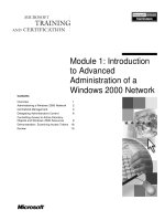
CAN Controller Area Network docx
Bạn đang xem bản rút gọn của tài liệu. Xem và tải ngay bản đầy đủ của tài liệu tại đây (5.19 MB, 36 trang )
10/14/2012
1
CAN
Controller
Area Network
10/14/2012
2
10/14/2012
3
Gesellschaft mit beschränkter Haftung (abbreviated GmbH (most common),
GesmbH or Ges.m.b.H.), German for "company with limited liability"
Carrier Sense Multiple Access (CSMA) is a probabilistic Media Access Control (MAC) protocol in which a node
verifies the absence of other traffic before transmitting on a shared transmission medium
CAN uses a nondestructive bitwise arbitration, which means that messages remain intact after arbitration is
completed even if collisions are detected. All the arbitration takes place without corruption or delay of the
message that wins the arbitration.
10/14/2012
4
CAN Standards
CAN ISO Standardization:
– ISO PRF 16845 : CAN Conformance Test Plan
– ISO PRF 11898-1: CAN Transfer Layer
– ISO PRF 11898-2: CAN High Speed Physical Layer
– ISO DIS 11898-3: CAN Fault Tolerant Physical Layer
– ISO DIS 11898-4: TTCAN Time Triggered CAN
The Layered ISO 11898:1993 Standard Architecture
CAN bus Cables and Connectors
Bus speed Cable type
Cable
resistance/m
Terminator Bus Length
50 kbit/s at 1000 m
0.75 0.8 mm2
AWG18
70 mOhm 150 300 Ohm 600 1000 m
100 kbit/s at 500 m
0.5 0.6 mm2
AWG20
< 60 mOhm 150 300 Ohm 300 600 m
500 kbit/s at 100 m
0.34 0.6 mm2
AWG22, AWG20
< 40 mOhm 127 Ohm 40 300 m
1000 kbit/s at 40 m
0.25 0.34 mm2
AWG23, AWG22
< 26 mOhm 124 Ohm 0 40 m
Pin
Descri
ption
Colour
1
V- Black
2
CAN_L Red
3
CAN_H Green
4
V+ Yellow
Pin Description Colour
1
nc -
2
V- Black
3
CAN_L Red
4 CAN_H Green
5 V+ Yellow
6 nc -
Pin Description Color
1
Drain Bare
2
V+ Red
3
V- Black
4
CAN_H White
5
CAN_L Blue
10/14/2012
5
Unshielded twisted pairShielded twisted pair
Pin Signal Description
1 - Reserved
2 CAN_L CAN_L bus line dominant low
3 CAN_GND CAN Ground
4 - Reserved
5 (CAN_SHLD) Optional CAN Shield
6 GND Optional Ground
7 CAN_H CAN_H bus line dominant high
8 - Reserved
9 (CAN_V+) Optional CAN external supply
CAN bus Cables and
Connectors
ISO11898 NOMINAL BUS LEVELS
10/14/2012
6
CAN bus Nominal ISO 11992 Bus Levels
CAN COMPARISON
10/14/2012
7
MCP2551
High-Speed CAN Transceiver
Dual in-line package
Small-outline integrated circuit
AN228
MCP2510
Stand-Alone CAN Controller with SPI™ Interface
TYPICAL SYSTEM IMPLEMENTATION
BLOCK DIAGRAM
10/14/2012
8
10/14/2012
9
Collision Avoidance
Bus (4 x Rx)
dominant
recessive
Listening Mode
Listening Mode
DLC
Data
Listening Mode
Node 1 (Tx)
Node 2 (Tx)
Node 3 (Tx)
Node 4 (Tx)
S R
O Identifier T Control Data
F 10 9 8 7 6 5 4 3 2 1 0 R Field Field
10/14/2012
10
CAN bus Bit-Stuffing Rule
• One characteristic of Non-Return-to-Zero code is that the signal provides no edges that can be used
for resynchronization if transmitting a large number of consecutive bits with the same polarity.
Therefore bit-stuffing is used to ensure synchronization of all bus nodes???.
• This means that during the transmission of a message, a maximum of five consecutive bits may have
the same polarity.
• The bit-stuff area in a CAN bus frame includes the SOF, Arbitration field, Control field, Data field
and CRC field.
10/14/2012
11
AN754
Understanding Microchip’s CAN Module Bit Timing
Time Quantum
OSC
OSC
F
BRP
TBRPTQ
)1(2
)1(2
TQ AND THE BIT PERIOD
PROGRAMMING THE TIMING SEGMENTS
The are several requirements for programming the
CAN bit timing segments.
1. PropSeg + PS1 ≥ PS2
2. PropSeg + PS1 ≥ t
prop
3. PS2 > SJW
Baud Rate Prescaler(BRP)
)(2
drvcmpbusprop
tttt
Signal’s round trip time on the physical bus (t
bus
),
the output driver delay (t
drv
), and the input
comparator delay (t
cmp
).
10/14/2012
12
AN754
Understanding Microchip’s CAN Module Bit Timing
CAN BIT TIMING CONTROL REGISTERS (MCP2510 CNF REGISTERS)
AN754
Understanding Microchip’s CAN Module Bit Timing
THE CAN BIT TIME
Nominal Bit Rate (NBR) is defined in the CAN specification as the number of bits
per second transmitted by an ideal transmitter with no resynchronization:
bit
bit
t
fNBR
1
The Nominal Bit Time (NBT), or t
bit
, is made up of
non overlapping segments
21Pr PSPSogSegSyncSegbit
ttttt
CAN BIT TIME SEGMENTS
The Synchronization Segment (SyncSeg) is used to synchronize the nodes on the bus. Bit edges
are expected to occur within the SyncSeg. This segment is fixed at 1TQ.
All nodes on a given CAN bus must have the same NBT.
The Propagation Segment (PropSeg) exists to compensate for physical delays between nodes.
The PropSeg is programmable from 1 - 8TQ.
)(_Pr
Q
prog
T
t
UPROUNDogSeg
The two phase segments, PS1 and PS2 are used to compensate for edge phase errors on the
bus. PS1 can be lengthened or PS2 can be shortened by resyncronization.
The Synchronization Jump Width (SJW) adjusts the bit clock as necessary by 1 - 4TQ (as
configured) to maintain synchronization with the transmitted message.
10/14/2012
13
CAN BIT RATE VS. BUS LENGTH
Propagation delay between nodes
)(2
drvcmpbusprop
tttt
10/14/2012
14
Given:
• Oscillator = 20 MHz
• Bit Rate = 500K BPS
• BRT = 0, t
prop
= 750 ns
Establishing the Time Quantum, Establish the Time Segment
s
f
tNBT
bit
bit
2
500000
11
ns
F
BRP
TQ
OSC
100
1020
2)1(2
6
8)
100
750
(_)(_Pr UPROUND
T
t
UPROUNDogSeg
Q
prog
PS1 = 7, PS2 = 4
The selected sample point should be near the 80% value
Sample Point = (1 + ProgSeg + PS1) / (1 + ProgSeg + PS1 +PS2)
= (1 +8+7) / (1 + 8+7 + 4)
= 0.80 = 80%
RESYNCHRONIZATION
• Resynchronization is implemented to maintain the initial synchronization that was
established by the hard synchronization.
• Without resynchronization, the receiving nodes could get out of synchronization
due to oscillator drift between nodes.
• Resynchronization is achieved by implementing a Digital Phase Lock Loop (DPLL)
function which compares the actual position of a recessive-to-dominant edge on
the bus to the position of the expected edge (within the SyncSeg) and adjusting the
bit time as necessary.
• The phase error of a bit is given by the position of the edge in relation to the
SyncSeg, measured in TQ, and is defined as follows:
• e = 0; the edge lies within the SyncSeg.
• e > 0; the edge lies before the sample point. (TQ added to PS1).
• e < 0; the edge lies after the sample point of the previous bit. (TQ
subtracted from PS2)
10/14/2012
15
SYNCHRONIZING
THE BIT TIME
Phase Locked Loops for High-Frequency Receivers and Transmitters
Voltage Control Oscillator
V
I
and V
out
has at the same frequency 1
566 Voltage-Controlled Oscillator
10/14/2012
16
The CAN protocol defines four different types of messages:
Data frame. A data frame carries data from a transmitter to the receivers.
Remote frame. A remote frame is transmitted by a node to request the transmission of the data
frame with the same identifier.
Error frame. An error frame is transmitted by a node on detecting a bus error.
Overload frame. An overload frame is used to provide for an extra delay between
the preceding and the succeeding data or remote frames.
Data frames and remote frames are separated from preceding frames by an interframe space.
10/14/2012
17
Standard Data Frame
EXTENDED DATA FRAME
MCP2510
MCP2510
10/14/2012
18
ERROR DATA FRAME
MCP2510
10/14/2012
19
OVERLOAD FRAME
MCP2510
10/14/2012
20
lnterframeSpace IFS
lnterframe space for non error-passive
nodes or receiver of previous message
Interframe space for error-passive nodes
Message Validation
• The point in time at which a message is taken to be valid is
different for the transmitters and receivers of the message.
• The message is valid for the transmitter if there is no error
until the end-of-frame. If a message is corrupted,
retransmission will follow automatically and according to the
rules of prioritization. In order to be able to compete for bus
access with other messages, retransmission has to start as soon
as the bus is idle.
• The message is valid for the receiver if there is no error until
the last but one bit of the end-of-frame
10/14/2012
21
Message Filtering
• A node uses filter(s) to decide whether to work
on a specific message.
• Message filtering is applied to the whole
identifier. A node can optionally implement mask
registers that specify which bits in the identifier are
examined with the filter.
If mask registers are implemented, every bit of the
mask registers must be programmable;
in other words, they can be enabled or disabled for
message filtering. The length of the mask register
can comprise the whole identifier or only part of it.
MESSAGE ACCEPTANCE MASK AND FILTER OPERATION
Acceptance Mask : A “0” in a bit location is “don’t-care”. A “1” in a bit location tells the CAN Plus adapter to
check the incoming message against the filter.
Messages with the ID range of 0x120 through 0x13F will pass through the adapter
10/14/2012
22
Cyclic Redundancy Check
Arithmetic Modulo 2
The addition rules are as follows:
Find the sum of 1011
2
and
110
2
modulo 2.
The multiplication table is equally simple:
0 * 0 = 0
0 * 1 = 1 * 0 = 0
1 * 1 = 1
The subtraction table:
0 - 0 = 0
0 - 1 = 1
1 - 0 = 1
1 - 1 = 0
Cyclic Redundancy Check
Modulo 2 division can be performed in a manner similar to arithmetic long
division. Subtract the denominator (the bottom number) from the leading parts of
the enumerator (the top number). Proceed along the enumerator until its end is
reached. Remember that we are using modulo 2 subtraction. For example, we can
divide 100100111 by 10011 as follows:
10/14/2012
23
CRC
CRC
0 1 1 1 0 0 1 0
Data
The key used by the Ethernet is 0x04c11db7. It corresponds
to the polynomial: x
32
+ x
26
+ + x
2
+ x + 1
With 16 bit CRC (detecting error)
%998.99
65536
65535
2
12
16
16
10/14/2012
24
10/14/2012
25