Intuitive Programming System Walk-Through For Lathes doc
Bạn đang xem bản rút gọn của tài liệu. Xem và tải ngay bản đầy đủ của tài liệu tại đây (3.55 MB, 38 trang )
ES0609 rev D 4/09
1
Intuitive
Programming
System
Walk-Through
For Lathes
ES0609 rev D 4/09
2
In t r o d u c t I o n
These instructions are an in-depth look at each of the Intuitive Programming System (IPS) menus. A more
formal description is given for each of the entries to help better dene the on-screen help for new users.
These instructions are to be used with the Lathe Operator’s Manual (96-8700) and Toolroom Lathe Operator’s
Addendum (96-0112)
The menus are navigated by using the left and right arrow keys. To select a menu item, press Write/Enter.
Some menus have sub-menus, in which case, use the left and right arrow keys and press Write/Enter to
select a sub-menu.
Use the arrow keys to navigate through the variables, enter values by using the number pad, and then press
Write/Enter.
To exit, or go back to another selection, press Cancel.
Pressing any of the buttons under the “Display” heading will exit the IPS menus, as will any of the mode keys
(i.e. Edit, Mem, MDI, etc.). To return to the IPS menu, press Handle Jog.
A representation of the machine keypad is included at the end of this document for reference.
This guide will help the user develop full CNC programs by means of the IPS screen. Note that a program
entered through the Toolroom Lathe screens is also accessible by going to full CNC MDI mode. The program
can be edited and saved from the full CNC mode.
NOTE: The IPS menu is displayed at power up, and is available in the following
congurations:
• 10” LCD and software version 7.xx and earlier - IPS
• 15” LCD and software version 8.03 and earlier - IPS (upgradable to Prole Creator)
• 15” LCD and software version 8.04A and later - IPS with Prole Creator
Ma n u a l Mo d e
Power on the machine and press RESET until all alarms have cleared. Press POWER ON/RESTART to zero
the machine. The IPS menu can now be accessed by pressing MDI DNC, then pressing PRGRM CONVRS.
Press WRITE/ENTER to display the IPS menu MANUAL tab.
GROOVINGTHREAD RE-CUTTHREADINGDRILL &TAPCHAMFER&RADIUSTURN&FACECHAMFERSETUPMANUAL
X AND Z AXES
THE AXES CAN BE ELECTRONICALLY LOCKED AND UNLOCKED. THIS IS SHOWN BY
XZ-MAN DISPLAYED AT THE BOTTOM OF THE SCREEN. IN THIS MODE BOTH THE
X AND Z AXES ARE UNLOCKED AND CAN BE POSITIONED USING THE MANUAL
HAND WHEELS. PRESSING [SHIFT] AND EITHER [+X] OR [-X], [+Z], OR
[-Z] WILL ELECTRONICALLY LOCK THAT AXIS. PRESSING [SHIFT] AND THE
SAME BUTTONASECOND TIME WILL UNLOCK THE AXIS.
SPINDLE
THE SPINDLE IS COMMANDED BY ENTERINGAVALUE FOR THE SPINDLE SPEED
AND PRESSING EITHER THE [FWD] OR [REV] BUTTONS. THE SPINDLE SPEED
OVERRIDE KEYS (+/-10%) CAN BE USED TO ADJUST THE COMMANDED SPEED.
ES0609 rev D 4/09
3
X and Z Axes
Just below the on-screen text is a line of text that shows the state the lathe is in. For example, “X -MAN”
means the X -axis is in manual mode. No text beneath the on-screen help means both axes (X and Z are
locked. In this case the axes can be jogged, by pressing +X/-X or +Z/-Z and then using the jog handle on the
pendant. Select a jog speed before using the jog handle.
Spindle
The spindle is controlled using the keys on the control pendant. Enter a spindle speed; for example, press 5,
then 0, then Write/Enter. This will enter a speed of 50RPM. Ensure the area around the spindle is free of tools
and workpieces, press the hold to run switch and then press either the FWD or REV button.
The spindle speed override keys ( +/- 10%) can be used to adjust the commanded speed. This also works on
most screens.
The spindle is stopped by letting go of the hold to run switch, pressing Reset, or the pressing the Stop button.
Se t u p
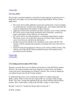
Stock Setup
GROOVINGGROOVINGTHREAD RE-CUTTHREADINGDRILL &TAPCHAMFER&RADIUSTURN&FACEMANUALSETUP
STOCK TOOL WORK TAILSTOCK
STOCK DIA.
STOCK LENGTH
STOCK FACE
0.1000 in
HOLE SIZE
0.0000 in
JAW THICKNESS
2.0000 in
2.0000 in
1.5000 in
CLAMP STOCK
JAW HEIGHT
STEP HEIGHT
3.0000 in
3.0000 in
0.5000 in
STOCK JAWS BAR FEEDER
Stock Dia. – Controls the diameter of the raw part that will be displayed in live image.
Stock Length – Controls the length of the raw part that will be displayed in live image.
Stock Face – Controls the Z stock face of the raw part that will be displayed in live image.
Hole Size – Controls the stock hole of the raw part that will be displayed in live image.
Jaw Thickness – Controls the thickness of the chuck jaws that will be displayed in live image.
Jaw Height – Controls the height of the chuck jaws that will be displayed in live image.
Step Height –
Clamp Stock – Controls the clamp stock size of the chuck jaws that will be displayed in live image.
Push Length –
ES0609 rev D 4/09
4
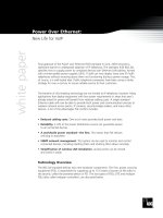
Tool Offsets
Tool offsets are described in detail in the Operator’s manual. See the “Tool Nose Compensation” section
within the “Operation/Programming” Tab for specic instructions on Radius, Radius Wear, Taper, and Tip.
STOCK TOOL WORK TAILSTOCK
TOOL
1
TOOL TYPE
OFFSET NUM
X OFFSET
0.0000 in
Z WEAR
RADIUS
TIP
0
TOOL SHANK
0.0000 in
TL THICKNESS
INSRT THCKNES
TOOL NOSE
INSERT HEIGHT
X WEAR TOOL LENGTH FROM CENTER
0.0000 inCUT OFF
1
Z OFFSET
0.0000 in
STEP HEIGHT DIAMETER
0.0000 in
0.0000 in
0.0000 in
0.0000 in
0 deg
0.0000 in
0.0000 in
0.0000 in
0.0000 in
0.0000 in
Selected Tool: 1
Active Tool: 1
Press [TURRET FWD] or
[TURRET REV] to change the
selected tool.
Press [NEXT TOOL] to make
selected tool active.
GROOVINGGROOVINGTHREAD RE-CUTTHREADINGDRILL &TAPCHAMFER&RADIUSTURN&FACEMANUALSETUP
Tool – The current tool number. Use the turret FWD/REV or the Next Tool buttons to set-up another tool.
Tool Type – Right/Left arrows select among 16 tool types: Drill, Tap, Vert Tap, Vert Drill, End Mill, V End Mill,
Ballnose, V Ballnose, OD Turn, ID Bore, OD Groove, ID Groove, Face Groove, OD Thread, ID Thread and
Cut Off.
Offset Num –
X Offset – The X axis offset for the current tool. Press X Dia Meas to record this position.
X Wear – The amount of tool wear, in the X axis for the current tool.
Z Offset – The Z axis offset for the current tool. Press Z Face Meas to record this position.
Z Wear – The amount of tool wear, in the Z axis for the current tool.
Radius** – The tip radius of the current tool.
Tip** – Tool tip direction will be a value of 0-9. Must be entered to use Cutter Compensation
Tool Shank –
Tool Length –
Step Height –
TL Thickness –
Tool Nose – The nose radius of the current tool.
Insert Height –
From Center –
Diameter – Compensation value for part deection.
**Must be entered to use Cutter Compensation; See the Operator’s manual for information on Cutter
Compensation.
ES0609 rev D 4/09
5
Work Offsets
STOCK TOOL WORK TAILSTOCK
XOffset
Wrk Zero Ofst
54
0.
ZOffset
0.
GROOVINGGROOVINGTHREAD RE-CUTTHREADINGDRILL &TAPCHAMFER&RADIUSTURN&FACEMANUALSETUP
Work Zero Offset – Press the Up and Down arrows to change the displayed Work Zero Offset.
X Offset – Press Write to add or F1 to set position. Enter a value and either press Write to add the value to
the current value, or F1 to replace the value with the entered value.
Z Offset – Press Write to add F1 to set or Part Zero Set to record current position. Enter a value and either
press Write to add the value to the current value, or F1 to replace the value with the entered value. Press Part
Zero Set to record the Z Offset current position.
Tailstock Setup
STOCK TOOL WORK TAILSTOCK
LIVE CTR ANG
60.000 deg
DIAMETER
LENGTH
2.0000 in
TS POSITION
TS OFFSET
RETRACT DIST
0.0000 in
X CLEARANCE
Z CLEARANCE
ADVANCE DIST
0.0000 in
0.0000 in
1.2500 in
NOT MODIFIABLE
TS HOLD POINT is the sum of
TS POSITION and TS OFFSET and
is stored in setting 107.
-10.0000 in
0.0000 in -0.5000 in
TS HOLD POINT
0.0000 in
GROOVINGGROOVINGTHREAD RE-CUTTHREADINGDRILL &TAPCHAMFER&RADIUSTURN&FACEMANUALSETUP
Live Center Angle – Controls center angle of tailstock.
Diameter – Controls the diameter of the tailstock.
Length – Controls the length of the tailstock.
TS Position –
TS Offset –
ES0609 rev D 4/09
6
Retract Dist – The distance from the Hold Point (Setting 107) the tail stock will retract when commanded.
This setting should be a positive value. Press Write to add F1 to set or Part Zero Set to record current
position. Enter a value and either press Write to add the value to the current value, or F1 to replace the value
with the entered value. Press Part Zero Set to record the Z Offset current position.
Advance Dist – When the tail stock is moving toward the Hold Point (Setting 107), this is the point where it
will stop its rapid movement and begin a feed. This setting should be a positive value. Press the Up and Down
arrows to change the displayed Work Zero Offset.
X Clearance – Works with Z Clearance to dene a tail stock travel restriction zone that limits interaction
between the tail stock and the tool turret. It determines the X-axis travel limit when the difference between
the Z-axis location and the tail stock location falls below the value in Z Clearance. If this condition occurs
and a program is running, an alarm is generated. When jogging, no alarm is generated, but travel is limited.
Press Write to add or F1 to set position. Enter a value and either press Write to add the value to the current
value, or F1 to replace the value with the entered value. When highlighting X CLEARANCE, pressing X DIA
MEAS takes the value of the X axis and places it in X CLEARANCE. Pressing ORIGIN when highlighting X
CLEARANCE sets clearance to max travel.
Z Clearance – Minimum allowable difference between the Z-axis and the tail stock. A value of -1.0000 means
that when the X-axis is below the X clearance plane, the Z-axis must be more than 1 inch away from the tail
stock position in the Z-axis negative direction. The default value for this setting is zero. Press Write to add F1
to set or Part Zero Set to record current position. Enter a value and either press Write to add the value to the
current value, or F1 to replace the value with the entered value. Press Part Zero Set to record the Z Offset
current position. When highlighting Z CLEARANCE, pressing Z FACE MEAS takes the value of the Z axis and
places it in Z CLEARANCE. Pressing ORIGIN when highlighting Z CLEARANCE sets clearance to zero.
au t o M a t I c Mo d e
On each of the following interactive screens, the user is asked to enter data needed to complete common
machining tasks. When all data has been entered, press “Cycle Start” to begin the machining process.
The following are examples of the types of the Automatic Mode screens and the denitions of the variables
that will need to be entered.
Turn and Face - Rapid
This mode is for making a rapid move.
GROOVINGTHREAD RE-CUTTHREADINGDRILL &TAPCHAMFER&RADIUSMANUALSETUP
RAPID FEED OD TURN FACE
TURN&FACE
ID TURN PROFILE
TOOL NUMBER
1
WORK OFFSET
54
X POSITION
0.0000 in
Z POSITION
0.0000 in
Press <CYCLE START> to run
in MDI or <F4> to record
output toaprogram
Tool Number – Enter the tool to be used.
Work Offset – Enter the work offset to be used.
X Position – Enter end point or move tool to end point desired. Press X DIA. MEAS to record this position.
ES0609 rev D 4/09
7
Z Position – Enter end point or move tool to end point desired. Press Z FACE MEAS to record this position.
Turn and Face - Feed
This mode provides for straight line (linear) motion from the machines current position to the specied ‘X’
and ‘Z’ end points.
NOTE: The Feed command is a single pass movement for features smaller than the maximum
cut depth for the tool. For larger features use the turn and face programs.
RAPID FEED OD TURN FACEID TURN PROFILE
TOOL NUMBER
1
WORK OFFSET
54
DELTA X
0.0000 in
DELTA Z
0.0000 in
FEED PER REV
0.0000 in
SPINDLE RPM
0.0000 in
Press <CYCLE START> to run
in MDI or <F4> to record
output toaprogram
GROOVINGTHREAD RE-CUTTHREADINGDRILL &TAPCHAMFER&RADIUSMANUALSETUPTURN&FACE
Tool Number – Enter the tool to be used.
Work Offset – Enter the work offset to be used.
Delta X – Enter the X-coordinate of the end point of the linear motion desired.
Delta Z – Enter the Z-coordinate of the end point of the linear motion desired.
*Feed Per Rev. – Enter the feed per revolution (in inches or millimeters).
*Spindle RPM – Enter the spindle RPM.
*Mandatory Values
Advanced Users: In the full CNC mode this is a G01 command.
Turn & Face - OD Turn
This mode is for an outside diameter cut.
ES0609 rev D 4/09
8
RAPID FEED OD TURN FACEID TURN PROFILE
Press <CYCLE START> to run
in MDI or <F4> to record
output toaprogram
TOOL NUMBER
1
WORK OFFSET
54
ZSTART PT
0.0000 in
OUTSIDE DIA.
0.0000 in
DIA. TO CUT
Z DIMENSION
DEPTH OF CUT
0.0000 in
FEED PER REV
0.0000 in
MAX RPM
1000
SFM
500
FILLET RADII
0.0000 in
TOOL NOSE
0.0000 in
0.0000 in
0.0000 in
GROOVINGTHREAD RE-CUTTHREADINGDRILL &TAPCHAMFER&RADIUSMANUALSETUPTURN&FACE
Tool Number – Enter the tool to be used.
Work Offset – Enter the work offset to be used.
Z Start Pt – Enter the Z axis starting point.
Outside Dia. – Enter the current diameter of the work piece. Manually measure the diameter.
Dia. to Cut – Enter the nished diameter.
Z Dimension – Enter the Z axis dimension of the part from the Z start point.
Depth of Cut – Enter the depth of cut for each pass of the stock removal.
Feed Per Rev – Enter the feed per revolution.
MAX RPM – Enter the maximum spindle turning speed.
SFM – Enter the Surface Feed per Minute.
Fillet Radii – Enter the corner llet radii or enter ‘0’ for none.
Tool Nose – Enter the tool nose radius.
Turn & Face - ID Turn
This mode is for an inside diameter cut.
RAPID FEED OD TURN FACEID TURN PROFILE
Press <CYCLE START> to run
in MDI or <F4> to record
output toaprogram
TOOL NUMBER
1
WORK OFFSET
54
ZSTART PT
0.0000 in
INSIDE DIA.
0.0000 in
DIA. TO CUT
Z DIMENSION
DEPTH OF CUT
0.0000 in
FEED PER REV
0.0000 in
MAX RPM
1000
SFM
200
FILLET RADII
0.0000 in
TOOL NOSE
0.0000 in
0.0000 in
0.0000 in
GROOVINGTHREAD RE-CUTTHREADINGDRILL &TAPCHAMFER&RADIUSMANUALSETUPTURN&FACE
ES0609 rev D 4/09
9
Tool Number – Enter the tool to be used.
Work Offset – Enter the work offset to be used.
Z Start Pt – Enter the Z axis starting point.
Inside Dia. – Enter the current diameter of the work piece. Manually measure the diameter.
Dia. to Cut – Enter the nished diameter.
Z Dimension – Enter the Z axis dimension of the part from the Z start point.
Depth of Cut – Enter the depth of cut for each pass of the stock removal.
Feed Per Rev – Enter the feed per revolution.
MAX RPM – Enter the maximum spindle turning speed.
SFM – Enter the Surface Feed per Minute.
Fillet Radii – Enter the corner llet radii or enter ‘0’ for none.
Tool Nose – Enter the tool nose radius.
Advanced Users: In the full CNC mode this is a G71 command.
Turn & Face - Face
This mode is for making an end facing cut.
RAPID FEED OD TURN FACEID TURN PROFILE
Press <CYCLE START> to run
in MDI or <F4> to record
output toaprogram
TOOL NUMBER
1
WORK OFFSET
54
OUTSIDE DIA.
0.0000 in
DIA. TO CUT
0.0000 in
Z DIMENSION
DEPTH OF CUT
0.0350 in
FEED PER REV
0.0060 in
MAX RPM
1000
SFM
200
0.0000 in
GROOVINGTHREAD RE-CUTTHREADINGDRILL &TAPCHAMFER&RADIUSMANUALSETUPTURN&FACE
Tool Number – Enter the tool to be used.
Work Offset – Enter the work offset to be used.
Outside Dia. – Enter the current diameter of the work piece. Manually measure the diameter.
Dia. to Cut – Enter the nished diameter.
Z Dimension – Enter the Z axis dimension of the part from the Z start point.
Depth of Cut – Enter the depth of cut for each pass of the stock removal.
Feed per Rev – Enter the feed per revolution. This is the distance the tool will move for each revolution of the
spindle.
MAX RPM – Enter the maximum spindle turning speed.
SFM – Enter the Surface Feed per Minute.
Advanced Users: In the full CNC mode this is a G72 command.
NOTE: Entering a negative value for “Dia to Cut” causes the tool to pass spindle center
and machine the entire face of the part; Do Not enter a value larger than 100”.
ES0609 rev D 4/09
10
Turn & Face - Prole
This tab is only available if the machine has a control pendant with a 15” screen and lathe software version
8.04A or later.
RAPID FEED OD TURN FACEID TURN PROFILE
Press <CYCLE START> to run
in MDI or <F4> to record
output toaprogram
TOOL NUMBER
1
WORK OFFSET
54
CUT TYPE
HRZ TYPE I
XSTOCK ALLOW
0.0000 in
NUM OF PASSES
X DISTANCE
Z DISTANCE
FEED PER REV
0.0000 in
SPINDLE DIR
CUTTER COMP
COOLANT
MIRROR X
ZSTOCK ALLOW
0.0000 in
DEPTH OF CUT
0.0000 in
MAX RPM
0
SFM
0
GRAPHIC MODE
PROFILE NUMBR
0
FORWARD
OFF
OFF
OFF
OFF
N/A
N/A
N/A
GROOVINGTHREAD RE-CUTTHREADINGDRILL &TAPCHAMFER&RADIUSMANUALSETUPTURN&FACE
Tool Number – Enter the tool to be used.
Work Offset – Enter the work offset to be used.
Cut Type – Use the left/right cursor keys to select the type of cut (Horizontal, Vertical, Prole, Finish Fwd, Fin-
ish Rev).
X Stock Allow – Enter the amount to leave on the diameter of the prole.
Z Stock Allow – Enter the amount to leave on the faces of the prole.
Depth of Cut – Enter the depth of cut for each pass of the stock removal.
Num of Passes – Enter the number of cutting passes. (Must be a positive number).
X Distance – Enter the X-axis distance and direction from rst cut to last. (Radius value).
Z Distance – Enter the Z-axis distance and direction from rst cut to last.
Feed Per Rev – Enter the feed per revolution.
MAX RPM – Enter the maximum spindle turning speed.
SFM – Enter the Surface Feed per Minute.
Spindle Dir – Use the left/right cursor keys to select spindle direction (Forward/Reverse). This depends on
tool type.
ES0609 rev D 4/09
11
Cutter Comp – Use the left/right cursor keys to select cutter compensation (Off/Left/Right).
Coolant – Use the left/right cursor keys to turn coolant on or off (On/Off).
Mirror X – Use the left/right cursor keys to mirror the X axis (On/Off). This allows you to cut on the other side
of the part.
Graphic Mode – Use the left/right cursor keys to turn on/off Graphic Mode. This allows you to view the pro-
cess in graphics.
Prole Number – Enter the number of the prole to use, press Enter to open Prole Select or press F1 key.
Advanced Users: In the full CNC Mode, this is a G71 command.
Basic Prole Creation (Example)
1. Start the machine with IPS active.
2. Clear any alarms, then press Power Up/Reset to zero the machine.
3. Select the Setup tab, then the Work tab to set up the work offsets.
4. Select the Tool tab (under the Setup tab) to set up the tools to be used.
5. Press Cancel a few times to get out of the Setup tab. Select the Turn & Face tab, then the Prole tab.
6. Enter the tool number (1), set Cut Type to Horizontal, set X Stock Allow to 0.02, set Z Stock Allow to 0.005,
set Depth of Cut to 0.075, set Feed per Rev to 0.01, set Max RPM to 1500, set SFM to 350, set Graphic
Mode to ON and Prole Number to 1.
7. Select the Prole Number data box and press Write/Enter or press F1 when in the Prole tab. A Prole
Selector popup window is displayed. The Prole Selector popup is used to select a prole, alter an existing
prole, choose a storage location for a new prole or delete a prole.
*Empty
Empty
Empty
Empty
Empty
Empty
Empty
Empty
Empty
Empty
Empty
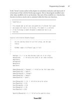
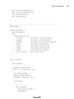
8. Select an ‘Empty’ slot and press Write/Enter to display the Prole Creator screen. This is used to draw a
prole on the screen using either the jog handle or entering data directly into the table.
X 1.0000
Z-1.0000
Profile Part Number: 1
Jog step size: 0.1
DeltaX: 2.0000
DeltaZ: 0.0000
F1-Help
F2-Exit & Save profile
F3-Exit without save
F4 - Activate Zoom
RAPD PT
START
1 FEED
1 FEED
1 FEED
TYPE
3.5000
0.0000
0.5000
1.0000
1.0000
0.1000
0.0000
1.0000
-0.2500
-1.0000
0.0000
0.0000
90.0000
135.0000
180.0000
0.0000
0.0000
0.0000
0.0000
0.5000
0.0000
0.0000
0.0000
0.0000
0.0000
XPOS Z POS ANGLE CHAMFER RADIUS
Prole Creator Screen Hot keys:
ES0609 rev D 4/09
12
F1 – Help screen popup. Lists available keys used in the Prole Creator along with a short description of each
key’s function.
F2 – Saves the prole on the screen, exits the Prole Creator screen and transfers control back to the Prole
tab.
F3 – Exits the Prole Creator screen and transfers control back to the Prole tab screen. Does not save the
prole’s data.
F4 – Activates and de-activates the zoom and scrolling feature.
INSERT – Inserts a line into the table. This feature will not work if the table is full (all 30 lines used).
ORIGIN – Clears all data in the table.
X JOG KEY – Jumps to the X-axis position in the data table for the currently selected row.
Z JOG KEY – Jumps to the Z-axis position in the data table for the currently selected row.
CURSOR KEYS – Moves around in the data table. If zoom is active, the cursor keys move the part around on
the screen.
(.0001), (.001), (.01), (.1) – Changes the jog step size while drawing in the graphic window.
To Build the Prole Shown:
a. Select the Rapd Pt row. Use the arrow keys to select the X POS column and enter 3.5. Use the arrow keys
to select the Z POS column and enter 0.1. Use the arrow keys to go to the beginning of the Start row.
b. Leave the Start PT at X0 Z0. Use the arrow keys to go to the beginning of the next line in the table (4
None). Press 1 to activate a Feed move.
c. Jog X POS to 0.5 by turning the handwheel clockwise, and press Write/Enter.
NOTE: Each handwheel click either increments or decrements the position by 0.1”.
Use the arrow keys to go to the beginning of the next line in the table and press 1 to activate a Feed move.
d. Press Write/Enter until X POS is selected. Jog X to 1.0 and press Write/Enter until Z POS is selected. Jog
Z to -0.25 and press Write/Enter.
Go to the beginning of the next line. Press 1 to activate a Feed move.
e. Press Write/Enter until Z POS is selected. Jog Z to -1.0 and press Write/Enter.
ES0609 rev D 4/09
13
Go to the beginning of the next line. Press 1 to activate a Feed move.
f. Press Write/Enter until X POS is selected. Jog X to 2.0 and press Write/Enter.
Go to the beginning of the next line. Press 1 to activate a Feed move.
g. Press Write/Enter until Z POS is selected. Jog Z to -1.5 and press Write/Enter.
Use the cursor keys to go back to the previous line and select the Radius column. Enter 0.25, press Write/
Enter and use the cursor keys to come back to this line.
Go to the beginning of the next line. Press 1 to activate a Feed move.
h. Press Write/Enter until X POS is selected. Jog X to 3.0. Press Write/Enter until Z POS is se lected. Jog Z to
-2.0 and press Write/Enter.
Go to the beginning of the next line. Press 1 to activate a Feed move.
ES0609 rev D 4/09
14
i. Press Write/Enter until Z POS is selected. Jog Z to -3.0 and press Write/Enter.
j. Press F2 to Save and exit the Prole Creator.
k. Press Cycle Start to cut the prole.
NOTE: The program may be saved to memory from MDI by typing in 0xxxxx and pushing
the Alter key. This action moves the program from MDI memory.
If Graphic Mode is set to ON in the Turn & Face Prole screen, when Cycle Start is pressed to run a prole, a
graphic screen is displayed showing the graphical representation of the prole.
Graphic Mode
To cut the prole on the other side of the workpiece, set Mirror X to ON in Turn & Face Prole screen (it is not
necessary to change Mirror X in Settings). When Cycle Start is pressed, the opposite side of the workpiece is
cut, and if Graphic Mode is set to ON, a graphical representation of the mirrored prole is displayed.
ES0609 rev D 4/09
15
Recalling Proles
The Prole Selector popup is used to select a prole, alter an existing prole, choose a storage location for
a new prole or delete a prole, and is accessed by pressing F1 in the Prole tab or by selecting the Prole
Number box and pressing Write/Enter.
Once in the Prole Selector popup screen, cursor to the number of the previously created prole and press
Alter. Cursor to any data cell to change its information, then press F2 to Exit the Prole Selector popup screen
and Save the new information, or F3 to Exit without Saving.
Prole Creator Help
Press F1 when in the Prole Creator screen to display a Prole Creator Help popup screen. This popup
screen lists available keys used in the Prole Creator along with a short description of each key’s function.
Exit and Save Profile
Exit without Saving Profile
Activate Zoom
ZOOM HELP
Zoom In
Zoom Out
Scroll Up
Scroll Down
Scroll Right
Scroll Left
Exit Zoom
DATA TABLE HELP
Enter Data Into Table
Insert Line Into Table
Clear All Data In Table
Go To X Axis Data Box
Go To Z Axis Data Box
Move Up To Next Data Box
Move Down To Next Data Box
Move Right To Next Data Box
Move LeftTo Next Data Box
(F2)
(F3)
(F4)
(PAGE UP)
(PAGEDOWN)
(UP CURSOR KEY)
(DOWN CURSOR KEY)
(RIGHT CURSOR KEY)
(LEFT CURSOR KEY)
(F4)
(WRITE/ENTER)
(INSERT)
(ORIGIN)
(X JOG KEY)
(Z JOG KEY)
(UP CURSOR KEY)
(DOWN CURSOR KEY)
(RIGHT CURSOR KEY)
(LEFT CURSOR KEY)
Exit and Save Prole - Exit Prole Creator screen and saves the prole you were working on into program
memory.
Exit without Saving Prole - Exit Prole Creator screen and does not save the prole you were working on.
Activate Zoom - Turns on the Zoom and Scrolling function.
Zoom In - Allows you to zoom into a part for a closer look.
Zoom Out - Allows you to zoom out from the part and see more in the window.
Scroll Up - Allows you to scroll the view window up.
Scroll Down - Allows you to scroll the view window down.
ES0609 rev D 4/09
16
Scroll Right - Allows you to scroll the view window to the right.
Scroll Left - Allows you to scroll the view window to the left.
Exit Zoom - Turns off the zoom and scrolling function.
Enter Data Into Table - Transfers data from command line into selected data box or accepts value jogged.
Insert Line Into Table - Moves selected line down and inserts new line into table. Will not work if table is full!
Clear All Data In Table - Clears all the data in current table and puts the table in its home position.
Go To X Axis Data Box - Highlights X axis data box and changes drawing cursor to only move in X direction.
Go To Z Axis Data Box - Highlights Z axis data box and changes drawing cursor to only move in Z direction.
Move Up To Next Data Box - Moves up to next data box above its current location. Will not move if already
at the top of the table.
Move Down To Next Data Box - Moves down to next data box below its current location. Will not move if
already at the bottom of the table.
Move Right To Next Data Box - Moves to the next data box to the right of its current location. Will wrap if
already at the far right.
Move Left To Next Data Box - Moves to the next data box to the left of its current location. Will wrap if
already at the far left.
Chamfer & Radius - OD Radius
This mode is used to cut an outside diameter radius.
GROOVINGTHREAD RE-CUTTHREADINGDRILL &TAPMANUALSETUPTURN&FACE
Press <CYCLE START> to run
in MDI or <F4> to record
output toaprogram
TOOL NUMBER
1
WORK OFFSET
54
ZSTART PT
0.0000 in
OUTSIDE DIA.
0.0000 in
OD RADIUS ID RADIUS
OD CHAMFER ID CHAMFER
RADIUS
0.0000 in
0.0500 in
0.0060 in
MAX RPM
1000
SFM
200
DEPTH OF CUT
FEED PER REV
TOOL NOSE
0.0310 in
CHAMFER&RADIUS
Tool Number – Enter the tool to be used.
Work Offset – Enter the work offset to be used.
Z Start PT – Enter the Z axis starting point.
Outside Dia. – Enter the current diameter of the work piece. Manually measure the diameter.
ES0609 rev D 4/09
17
Radius – Enter the desired radius. This is the desired corner radius. Note that the larger the radius or material
to be removed, the more passes required to rough out the prole.
Depth of Cut – Enter depth of cut for each pass of stock removal. This is the amount of stock to be removed
on each tool pass. A pass must be less than or equal to maximum single pass cut depth for selected tool.
Feed Per Rev – Enter feed per revoultion. This is distance tool will move for each revolution of the spindle.
MAX RPM – Enter the maximum spindle turning speed.
Tool Nose – Enter the tool nose radius. This is the radius of the selected tool. Normally this information is
included with the tool.
SFM – Enter the Surface Feed per Minute.
Advanced Users: In the full CNC mode this is a G71 command.
Chamfer & Radius - I.D. Radius
This mode is used to cut an inside diameter radius.
Press <CYCLE START> to run
in MDI or <F4> to record
output toaprogram
OD RADIUS ID RADIUS
OD CHAMFER ID CHAMFER
TOOL NUMBER
1
WORK OFFSET
54
ZSTART PT
0.0000 in
INSIDE DIA.
0.0000 in
RADIUS
0.0000 in
0.0000 in
0.0000 in
MAX RPM
1000
SFM
200
DEPTH OF CUT
FEED PER REV
TOOL NOSE
0.0000 in
GROOVINGTHREAD RE-CUTTHREADINGDRILL &TAPMANUALSETUPTURN&FACECHAMFER&RADIUS
Tool Number – Enter the tool to be used.
Work Offset – Enter the work offset to be used.
Z Start PT – Enter the Z axis starting point.
Inside Dia. – Enter the current diameter of the work piece. Manually measure the diameter.
ES0609 rev D 4/09
18
Radius – Enter the desired radius. This is the desired corner radius. Note that the larger the radius or material
to be removed, the more passes required to rough out the prole.
Depth of Cut – Enter the depth of cut for each pass of the stock removal. This is the amount of the stock to
be removed on each tool pass. A pass must be less than or equal to the maximum single pass cut depth for
the selected tool.
Feed Per Rev – Enter the feed per revoultion. This is the distance the tool will move for each revolution of the
spindle.
MAX RPM – Enter the maximum spindle turning speed.
Tool Nose – Enter the tool nose radius. This is the radius of the selected tool. Normally this information is
included with the tool.
SFM – Enter the Surface Feed per Minute.
Advanced Users: In the full CNC mode this is a G71 command.
Chamfer & Radius - OD Chamfer
This mode is used to cut an outside diameter chamfer.
Press <CYCLE START> to run
in MDI or <F4> to record
output toaprogram
OD RADIUS ID RADIUS
OD CHAMFER ID CHAMFER
TOOL NUMBER
1
WORK OFFSET
54
ZSTART PT
0.0000 in
OUTSIDE DIA.
0.0000 in
CHAMFER
0.0000 in
0.000 deg.
0.0500 in
FEED PER REV
0.0060 in
TOOL NOSE
0.0315 in
ANGLE
DEPTH OF CUT
MAX RPM
1000
200
SFM
GROOVINGTHREAD RE-CUTTHREADINGDRILL &TAPMANUALSETUPTURN&FACECHAMFER&RADIUS
Tool Number – Enter the tool to be used.
Work Offset – Enter the work offset to be used.
Z Start PT – Enter the Z axis starting point.
Outside Dia. – Enter the outside diameter of the part. Manually measure the work piece.
ES0609 rev D 4/09
19
Chamfer – Enter the Z dimension of the chamfer desired. Entered value must be positive.
Angle – Enter the angle of the chamfer (0°–90°). Entered value must be positive.
Depth of Cut – Enter the depth of cut for each pass of the stock removal.
Feed Per Rev – Enter the feed per revolution.
MAX RPM – Enter the maximum spindle turning speed.
Tool Nose – Enter the tool nose radius.
SFM – Enter the Surface Feed per Minute.
Advanced Users: In the full CNC mode this is a G71 command.
Chamfer & Radius - ID Chamfer
This mode is used to cut an outside diameter chamfer.
Press <CYCLE START> to run
in MDI or <F4> to record
output toaprogram
OD RADIUS ID RADIUS
OD CHAMFER ID CHAMFER
TOOL NUMBER
1
WORK OFFSET
54
ZSTART PT
0.0000 in
INSIDE DIA.
0.0000 in
CHAMFER
0.0000 in
0.000 deg.
0.0400 in
FEED PER REV
0.0060 in
TOOL NOSE
0.0315 in
ANGLE
DEPTH OF CUT
MAX RPM
1000
200
SFM
GROOVINGTHREAD RE-CUTTHREADINGDRILL &TAPMANUALSETUPTURN&FACECHAMFER&RADIUS
Tool Number – Enter the tool to be used.
Work Offset – Enter the work offset to be used.
Z Start PT – Enter the Z axis starting point.
Inside Dia. – Enter current diameter of work piece (outside diameter of part). Manually measure work piece.
ES0609 rev D 4/09
20
Chamfer – Enter the Z dimension of the chamfer desired. Entered value must be positive.
Angle – Enter the angle of the chamfer (0°-90°). Entered value must be positive.
Depth of Cut – Enter the depth of cut for each pass of the stock removal.
Feed Per Rev – Enter the feed per revolution.
MAX RPM – Enter the maximum spindle turning speed.
Tool Nose – Enter the tool nose radius.
SFM – Enter the Surface Feed per Minute.
Advanced Users: In the full CNC mode this is a G71 command.
Drill & Tap - Drill
This mode is a drill cycle that can pause at the bottom of the hole.
GROOVINGTHREAD RE-CUTTHREADINGMANUALSETUPTURN&FACE
Press <CYCLE START> to run
in MDI or <F4> to record
output toaprogram
DRILL PECK DRILL
TAP REVERSE TAP
CHAMFER&RADIUS
TOOL NUMBER
1
WORK OFFSET
54
ZSTART PT
0.0000 in
DEPTH OF HOLE
0.0000 in
0.0030 in
0.5000 sec
FEED PER REV
DWELL
MAX RPM
1000
DRILL &TAP
Tool Number – Enter the tool to be used.
Work Offset – Enter the work offset to be used.
Z Start PT – Enter the Z axis starting point.
Depth of Hole – Enter the depth to drill.
ES0609 rev D 4/09
21
Feed Per Rev – Enter feed per revolution (distance the tool will move for each revolution of the spindle).
MAX RPM – Enter the spindle RPM.
Dwell – Enter dwell time (time, in seconds, that the tool pauses at the bottom of the hole to clear chips).
Advanced Users: In the full CNC mode this is a G82 command.
Drill & Tap - Peck Drill
This mode is for drilling in a pecking motion in order to remove the chip build up while drilling the hole.
Press <CYCLE START> to run
in MDI or <F4> to record
output toaprogram
DRILL PECK DRILL
TAP REVERSE TAP
TOOL NUMBER
1
WORK OFFSET
54
ZSTART PT
0.0000 in
DEPTH OF HOLE
0.0000 in
0.0000 in
0.0000 sec
PECK DISTANCE
SPINDLE RPM
FEED PER REV
1000
GROOVINGTHREAD RE-CUTTHREADINGMANUALSETUPTURN&FACECHAMFER&RADIUSDRILL &TAP
Tool Number – Enter the tool to be used.
Work Offset – Enter the work offset to be used.
Z Start Pt – Enter the Z axis starting point.
Depth of Hole – Enter the depth to drill. Entered value must be positive.
Peck Distance – Enter the length of each ‘peck’ before retracting to clear chips. This is the distance the tool
will advance at each “peck”. This value cannot be negative.
Feed Per Rev – Enter feed per revolution (distance the tool will move for each revolution of the spindle).
Spindle RPM – Enter the spindle RPM. This is the commanded spindle speed.
Advanced Users: In the full CNC mode this is a G83 command.
Drill & Tap - Tap*
This mode is for cutting right hand threads using a tapping tool.
ES0609 rev D 4/09
22
Press <CYCLE START> to run
in MDI or <F4> to record
output toaprogram
DRILL PECK DRILL
TAP REVERSE TAP
TOOL NUMBER
1
WORK OFFSET
54
ZSTART PT
0.0000 in
TAP DEPTH
0.0000 in
0.0000 in
TPI
SPINDLE RPM
350
GROOVINGTHREAD RE-CUTTHREADINGMANUALSETUPTURN&FACECHAMFER&RADIUSDRILL &TAP
Tool Number – Enter the tool to be used.
Work Offset – Enter the work offset to be used.
Z Start PT – Enter the Z axis starting point.
Tap Depth – Enhter the depth to tap. Entered value must be positive.
TPI – (Threads per Inch) – Enter the number of Threads per Inch. This is how many threads to cut per inch.
Spindle RPM – Enter spindle RPM (commanded spindle speed). Spindle speed should not exceed 500 RPM.
Advanced Users: In the full CNC mode this is a G84 command.
(*Rigid Tapping Option needed.)
Drill & Tap - Reverse Tap*
This mode is for cutting left hand threads using a tapping tool.
ES0609 rev D 4/09
23
Press <CYCLE START> to run
in MDI or <F4> to record
output toaprogram
DRILL PECK DRILL
TAP REVERSE TAP
TOOL NUMBER
1
WORK OFFSET
54
ZSTART PT
0.0000 in
TAP DEPTH
0.0000 in
0.0000 in
TPI
SPINDLE RPM
350
GROOVINGTHREAD RE-CUTTHREADINGMANUALSETUPTURN&FACECHAMFER&RADIUSDRILL &TAP
Tool Number – Enter the tool to be used.
Work Offset – Enter the work offset to be used.
Z Start PT – Enter the Z axis starting point.
Tap Depth – The depth to tap. Entered value must be positive.
TPI – How many threads to cut per inch.
Spindle RPM – The commanded spindle speed. The spindle speed should not exceed 500 RPM.
Advanced Users: In the full CNC mode this is a G184 command.
(*Rigid Tapping Option needed.)
Threading - OD Thread
This mode is used for cutting outside diameter threads using multiple passes.
GROOVINGTHREAD RE-CUTMANUALSETUPTURN&FACE
Press <CYCLE START> to run
in MDI or <F4> to record
output toaprogram
CHAMFER&RADIUSDRILL &TAP
TOOL NUMBER
1
WORK OFFSET
54
ZSTART PT
0.0000 in
THREAD LENGTH
0.0000 in
OD THREAD
ID THREAD
OD THREAD REPAIR ID THREAD REPAIR
MINOR
0.0000 in
0.0000 in
0.000
DEPTH OF CUT
0.0150 in
TAPER
0.0000 in
MAJOR
TPI
SPINDLE RPM
1000
RIGHT
CHAMFER
OFF
THREAD DIR
COOLANT
OFF
THREADING
Tool Number – Enter the tool to be used.
Work Offset – Enter the work offset to be used.
Z Start Pt – Enter the Z axis starting point.
Thread Length – Enter the length of the threaded portion of the part. This value cannot be negative.
ES0609 rev D 4/09
24
Minor – Enter minor diameter of threads (smallest part of the thread (Min Diameter). Cannot be negative.
Major – Enter major diameter of threads (largest part of the thread (Max Diameter). Cannot be negative.
Manually measure the diameter of the work piece at the point where “X Dia Meas” was pressed.
TPI (Threads per Inch) – Enter number of Threads per Inch (how many threads to cut per inch of length).
Depth of Cut – Enter the amount of stock to be removed on each pass. Must be less than or equal to the
maximum single pass cut depth for the selected tool.
Spindle RPM – Enter the spindle RPM. This is the commanded spindle speed.
Taper – Enter a positive value for thread taper per ft.
Thread Dir – Enter ‘0’ for right hand threads or enter ‘1’ for left hand threads.
Chamfer – ‘ON’ turns on chamfer at end of threads. ‘OFF’ turns off chamfer at end of threads. (Check setting
95, 96, 86, 99).
Coolant – ‘ON’ turns on machine coolant. ‘OFF’ turns off machine coolant.
Advanced Users: Additional Settings may need to be modied to create the required groove. These setting
numbers are: 22, 28, 72, 73, 86, 95, 96, 99. See the denitions of the setting in the Operator’s Manual.
In the full CNC mode this is a G76 command.
Threading - ID Thread
This mode is used for cutting inside diameter threads using multiple passes.
Press <CYCLE START> to run
in MDI or <F4> to record
output toaprogram
TOOL NUMBER
1
WORK OFFSET
54
ZSTART PT
0.0000 in
THREAD LENGTH
0.0000 in
OD THREAD
ID THREAD
OD THREAD REPAIR ID THREAD REPAIR
MINOR
0.0000 in
0.0000 in
0.000
DEPTH OF CUT
0.0150 in
TAPER
0.0000 in
MAJOR
TPI
SPINDLE RPM
1000
RIGHT
CHAMFER
OFF
THREAD DIR
COOLANT
OFF
GROOVINGTHREAD RE-CUTMANUALSETUPTURN&FACECHAMFER&RADIUSDRILL &TAPTHREADING
Tool Number – Enter the tool to be used.
Work Offset – Enter the work offset to be used.
Z Start Pt – Enter the Z axis starting point.
Thread Length – Enter the length of the threaded portion of the part. This value cannot be negative.
Minor – Enter minor diameter of threads (smallest part of the thread (Min Diameter). Cannot be negative.
Major – Enter major diameter of the threads (largest part of the thread (Max Diameter). Cannot be negative.
Manually measure the diameter of the work piece at the point where “X Dia Meas” was pressed.
TPI (Threads per Inch) – Enter number of Threads per Inch (how many threads to cut per inch of length).
Depth of Cut – Enter the amount of stock to be removed on each pass. Must be less than or equal to the
maximum single pass cut depth for the selected tool.
Spindle RPM – Enter the spindle RPM. This is the commanded spindle speed.
Taper – Enter a positive value for thread taper per ft.
Thread Dir – Enter ‘0’ for right hand threads or enter ‘1’ for left hand threads.
ES0609 rev D 4/09
25
Chamfer – ‘0’ turns on chamfer at end of threads. ‘1’ turns off chamfer at end of threads. (Check setting 95,
96, 86, 99).
Coolant – ‘ON’ turns on machine coolant. ‘OFF’ turns off machine coolant.
Advanced Users: Additional Settings may need to be modied to create the required groove. These setting
numbers are: 22, 28, 72, 73, 86, 95, 96, 99. See the denitions of the setting in the Operator’s Manual.
In the full CNC mode this is a G76 command.
Threading - OD Thread Repair
This mode is for repairing outside diameter threads using multiple passes.
Press <CYCLE START> to run
in MDI or <F4> to record
output toaprogram
OD THREAD
ID THREAD
OD THREAD REPAIR ID THREAD REPAIR
REFERENCE
NOT SET
TPI
48.0
THRD HEIGHT
0.0131 in
TL CLEARANCE
0.1000 in
THREAD LENGTH
0.0000 in
3
0.0125 in
SPINDLE RPM
350
Z OFFSET
0.0000 in
THRDS TO CLR
DEPTH OF CUT
X OFFSET
RIGHT
CHAMFER
OFF
THREAD DIR
COOLANT
OFF
NO OF THREADS
0
TAPER
0.0000 in
0.0000 in
GROOVINGTHREAD RE-CUTMANUALSETUPTURN&FACECHAMFER&RADIUSDRILL &TAPTHREADING
Reference – Jog the tool into the threads, then press the X DIA MEAS key. 1 = reference point recorded.
TPI – Enter the number of Threads per Inch (or Threads per Millimeter).
Thread Height –
TL Clearance –
No Of Threads – Enter the number of threads from the tool to the end of the part.
Thread Length – Enter the length of the threaded portion of the part.
Threads to Clear –
Depth of cut – Enter the amount of stock to be removed on each pass.
Spindle RPM – Enter the spindle RPM.
Taper – Enter a positive value for thread taper per ft.
X Offset – Enter a value only if minor adjustments are needed in the X axis.
Z Offset – Enter a value only if minor adjustments are needed in the Z axis.
Thread Dir – Enter ‘0’ for right hand threads or enter ‘1’ for left hand threads.
Chamfer – ‘0’ turns on chamfer at end of threads. ‘1’ turns off chamfer at end of threads. (Check setting 95,
96, 86, 99).
Coolant – ‘ON’ turns on machine coolant. ‘OFF’ turns off machine coolant.
Threading - ID Thread Repair
This mode is for repairing outside diameter threads using multiple passes.