Suzaku Project Data Management Plan (PDMP) pot
Bạn đang xem bản rút gọn của tài liệu. Xem và tải ngay bản đầy đủ của tài liệu tại đây (839.67 KB, 59 trang )
Suzaku Project
Data Management Plan
(PDMP)
Suzaku Guest Observer Facility
NASA/GSFC, Greenbelt, MD 20771, USA,
and
Institute of Space and Astronautical Science (ISAS/JAXA)
Yoshinodai, Sagamihara, Kanagawa, 229 Japan
Version 2.0
September 27, 2007
Version History
v0.0 (September 9, 2005) — Revision from the PDMP of the Astro-E (1) project. Remove
explanations about the instruments.
v0.1 (December 3, 2005) — Revision with comments from Ken Ebisawa. Update the software
description. Remove documents about the XRS.
v0.2 (January 17, 2006) — Additiona l post-launch information included.
v1.0 (April 17, 2007) — First official ver sion, corresponding to Version 1.X processing.
v1.1 (April 20, 2007) — Including description in the Suza ku memo. Adding comments fr om
Yoshitaka Ishisaki.
v2.0 (September 27, 2007) — T he version co rresponding to Version 2.X processing. Adding
comments from Ken Ebisawa, Yoshitomo Maeda, Yukikatsu Terada, Tadayuki Takahashi,
Hironori Matsumoto, Masanobu Ozaki.
Contents
1 Introduction 4
1.1 Scope of this Document . . . . . . . . . . . . . . . . . . . . . . . . . . . . . . . . . . . . . . 4
1.2 Mission Overview . . . . . . . . . . . . . . . . . . . . . . . . . . . . . . . . . . . . . . . . . . 5
1.3 The Suzaku Guest Observer Facility . . . . . . . . . . . . . . . . . . . . . . . . . . . . . . . 5
1.4 Related Documents . . . . . . . . . . . . . . . . . . . . . . . . . . . . . . . . . . . . . . . . . 5
2 Observations Types 7
2.1 Observations Types . . . . . . . . . . . . . . . . . . . . . . . . . . . . . . . . . . . . . . . . . 7
2.1.1 In-Orbit Checkout . . . . . . . . . . . . . . . . . . . . . . . . . . . . . . . . . . . . . 7
2.1.2 Observatory Time . . . . . . . . . . . . . . . . . . . . . . . . . . . . . . . . . . . . . 7
2.1.3 Science Working Group Time . . . . . . . . . . . . . . . . . . . . . . . . . . . . . . . 7
2.1.4 GO Observations . . . . . . . . . . . . . . . . . . . . . . . . . . . . . . . . . . . . . . 8
2.1.5 Calibration Observations . . . . . . . . . . . . . . . . . . . . . . . . . . . . . . . . . 8
2.1.6 Tar get of Opportunity Observations . . . . . . . . . . . . . . . . . . . . . . . . . . . 8
2.1.7 HXD WAM Observations . . . . . . . . . . . . . . . . . . . . . . . . . . . . . . . . . 8
2.2 Proprietary Period . . . . . . . . . . . . . . . . . . . . . . . . . . . . . . . . . . . . . . . . . 8
2.3 Satellite and Instrument Monitoring . . . . . . . . . . . . . . . . . . . . . . . . . . . . . . . 9
2.4 Data Flow . . . . . . . . . . . . . . . . . . . . . . . . . . . . . . . . . . . . . . . . . . . . . . 9
2.4.1 Data Retrieval and Raw Data Archives . . . . . . . . . . . . . . . . . . . . . . . . . 9
2.4.2 Data Processing at ISAS and GSFC . . . . . . . . . . . . . . . . . . . . . . . . . . . 9
2.4.3 Data Delivery to Suzaku Observers . . . . . . . . . . . . . . . . . . . . . . . . . . . . 9
2.4.4 Suzaku Archives . . . . . . . . . . . . . . . . . . . . . . . . . . . . . . . . . . . . . . 9
3 Software Principles 12
3.1 General Software Design Principles . . . . . . . . . . . . . . . . . . . . . . . . . . . . . . . . 12
3.2 Suzaku Specific Design Principles . . . . . . . . . . . . . . . . . . . . . . . . . . . . . . . . . 12
3.3 Suzaku Software Standards . . . . . . . . . . . . . . . . . . . . . . . . . . . . . . . . . . . . 13
3.3.1 Languages . . . . . . . . . . . . . . . . . . . . . . . . . . . . . . . . . . . . . . . . . . 13
3.3.2 Coding Rules and Compiler Requirements . . . . . . . . . . . . . . . . . . . . . . . . 14
3.3.3 Systems Supported . . . . . . . . . . . . . . . . . . . . . . . . . . . . . . . . . . . . . 14
3.3.4 Coordination and Version Control . . . . . . . . . . . . . . . . . . . . . . . . . . . . 14
3.3.5 Documentation . . . . . . . . . . . . . . . . . . . . . . . . . . . . . . . . . . . . . . . 14
3.4 Suzaku FTOOLS Global Development Scheme . . . . . . . . . . . . . . . . . . . . . . . . . 14
3.5 Suzaku Ftools Relea se Pla n . . . . . . . . . . . . . . . . . . . . . . . . . . . . . . . . . . . . 16
4 Suzaku Function Libraries 17
4.1 Suzaku Specific Tasks (a ste
tool) . . . . . . . . . . . . . . . . . . . . . . . . . . . . . . . . . 17
4.1.1 Time Conversion . . . . . . . . . . . . . . . . . . . . . . . . . . . . . . . . . . . . . . 17
4.1.2 Coordinate Conversion . . . . . . . . . . . . . . . . . . . . . . . . . . . . . . . . . . . 17
4.1.3 Energy Calibration . . . . . . . . . . . . . . . . . . . . . . . . . . . . . . . . . . . . . 17
4.1.4 HK Information Acquisition . . . . . . . . . . . . . . . . . . . . . . . . . . . . . . . . 18
4.1.5 Other Tasks . . . . . . . . . . . . . . . . . . . . . . . . . . . . . . . . . . . . . . . . . 18
1
CONTENTS 2
4.2 Attitude and Orbit Related Tasks (atFunctions) . . . . . . . . . . . . . . . . . . . . . . . . 18
4.2.1 Attitude Information . . . . . . . . . . . . . . . . . . . . . . . . . . . . . . . . . . . . 18
4.2.2 Orbit Information . . . . . . . . . . . . . . . . . . . . . . . . . . . . . . . . . . . . . 18
4.2.3 Attitude and Orbit Information . . . . . . . . . . . . . . . . . . . . . . . . . . . . . . 18
4.3 Ray-Tracing Function Library (xrrt) . . . . . . . . . . . . . . . . . . . . . . . . . . . . . . . 19
5 Planning and Simulation Software 20
5.1 Observation Planning Software . . . . . . . . . . . . . . . . . . . . . . . . . . . . . . . . . . 20
5.1.1 TAKO (Timeline Assembler, Keyword Oriented) . . . . . . . . . . . . . . . . . . . . 20
5.1.2 MAKI . . . . . . . . . . . . . . . . . . . . . . . . . . . . . . . . . . . . . . . . . . . . 20
5.2 Simulation Softwar e . . . . . . . . . . . . . . . . . . . . . . . . . . . . . . . . . . . . . . . . 20
5.2.1 Counting Rate Simulation – P IMMS . . . . . . . . . . . . . . . . . . . . . . . . . . . 21
5.2.2 Spectr al Simulation – XSPEC . . . . . . . . . . . . . . . . . . . . . . . . . . . . . . . 21
5.2.3 XRT Ray-Tracing Library – libxrrt . . . . . . . . . . . . . . . . . . . . . . . . . . . . 22
5.2.4 Suzaku XIS Event Simulator xissim . . . . . . . . . . . . . . . . . . . . . . . . . . . 22
6 Data Analysis and Processing Software 23
6.1 Overview . . . . . . . . . . . . . . . . . . . . . . . . . . . . . . . . . . . . . . . . . . . . . . 23
6.2 Stage 0 – Satellite Specific Calibration . . . . . . . . . . . . . . . . . . . . . . . . . . . . . . 23
6.2.1 Orbit Determination . . . . . . . . . . . . . . . . . . . . . . . . . . . . . . . . . . . . 23
6.2.2 Attitude Determination . . . . . . . . . . . . . . . . . . . . . . . . . . . . . . . . . . 23
6.2.3 Raw Packet Telemetry Files . . . . . . . . . . . . . . . . . . . . . . . . . . . . . . . . 24
6.3 Stage 1 – Production of the First FITS Files . . . . . . . . . . . . . . . . . . . . . . . . . . 24
6.3.1 First Stage Software – mk1stfits . . . . . . . . . . . . . . . . . . . . . . . . . . . . . 25
6.3.2 Convention for naming First FITS Files . . . . . . . . . . . . . . . . . . . . . . . . . 26
6.4 Stage 2 – Instrument Specific Calibration . . . . . . . . . . . . . . . . . . . . . . . . . . . . 27
6.4.1 Stage 2-1 – Preprocess the Supplementary Data . . . . . . . . . . . . . . . . . . . . . 27
6.4.2 Stage 2-2 – Refine the First FITS Event Files . . . . . . . . . . . . . . . . . . . . . . 27
6.4.3 Stage 2-3 – Apply the Calibration Data . . . . . . . . . . . . . . . . . . . . . . . . . 28
6.4.4 Stage 2-4 – Classify Events . . . . . . . . . . . . . . . . . . . . . . . . . . . . . . . . 28
6.5 Stage 3 – Data Analysis . . . . . . . . . . . . . . . . . . . . . . . . . . . . . . . . . . . . . . 29
6.5.1 Stage 3-1 – Screen the Data . . . . . . . . . . . . . . . . . . . . . . . . . . . . . . . . 29
6.5.2 Stage 3-2 – Extract Scientific Products . . . . . . . . . . . . . . . . . . . . . . . . . . 30
6.5.3 Stage 3-3 – Generate Analys is Specific Data Sets . . . . . . . . . . . . . . . . . . . . 30
6.5.4 Stage 3-4 – Derive Scientific Results . . . . . . . . . . . . . . . . . . . . . . . . . . . 32
6.6 Pipeline Processing System . . . . . . . . . . . . . . . . . . . . . . . . . . . . . . . . . . . . 32
7 Calibration 35
7.1 Documentation . . . . . . . . . . . . . . . . . . . . . . . . . . . . . . . . . . . . . . . . . . . 35
7.2 Calibration Software . . . . . . . . . . . . . . . . . . . . . . . . . . . . . . . . . . . . . . . . 36
7.3 Calibration Database (CALDB) . . . . . . . . . . . . . . . . . . . . . . . . . . . . . . . . . . 36
7.3.1 Structure and Organization . . . . . . . . . . . . . . . . . . . . . . . . . . . . . . . . 36
7.3.2 Time-Dependent Calibration Files . . . . . . . . . . . . . . . . . . . . . . . . . . . . 36
7.3.3 Calibration File Name . . . . . . . . . . . . . . . . . . . . . . . . . . . . . . . . . . . 36
7.3.4 Versio n Control . . . . . . . . . . . . . . . . . . . . . . . . . . . . . . . . . . . . . . . 37
7.4 Important Calibration Files . . . . . . . . . . . . . . . . . . . . . . . . . . . . . . . . . . . . 38
7.4.1 General . . . . . . . . . . . . . . . . . . . . . . . . . . . . . . . . . . . . . . . . . . . 38
7.4.2 XRT . . . . . . . . . . . . . . . . . . . . . . . . . . . . . . . . . . . . . . . . . . . . . 38
7.4.3 XIS . . . . . . . . . . . . . . . . . . . . . . . . . . . . . . . . . . . . . . . . . . . . . 38
7.4.4 HXD . . . . . . . . . . . . . . . . . . . . . . . . . . . . . . . . . . . . . . . . . . . . . 39
7.5 Suzaku Calibration File Release Plan . . . . . . . . . . . . . . . . . . . . . . . . . . . . . . . 39
CONTENTS 3
8 Guest Observer Support 40
8.1 On-Line Service and Help . . . . . . . . . . . . . . . . . . . . . . . . . . . . . . . . . . . . . 4 0
8.2 Proposal Support . . . . . . . . . . . . . . . . . . . . . . . . . . . . . . . . . . . . . . . . . . 40
8.3 Observation Planning . . . . . . . . . . . . . . . . . . . . . . . . . . . . . . . . . . . . . . . 40
8.4 Pipeline Processing and Data Distribution . . . . . . . . . . . . . . . . . . . . . . . . . . . . 41
8.5 Data Analysis Support . . . . . . . . . . . . . . . . . . . . . . . . . . . . . . . . . . . . . . . 41
8.6 Community Oversight . . . . . . . . . . . . . . . . . . . . . . . . . . . . . . . . . . . . . . . 41
9 Suzaku Database and Archives 42
9.1 Suzaku Databases . . . . . . . . . . . . . . . . . . . . . . . . . . . . . . . . . . . . . . . . . 42
9.1.1 Proposal Data base . . . . . . . . . . . . . . . . . . . . . . . . . . . . . . . . . . . . . 42
9.1.2 Observation Database . . . . . . . . . . . . . . . . . . . . . . . . . . . . . . . . . . . 42
9.1.3 Processing Database . . . . . . . . . . . . . . . . . . . . . . . . . . . . . . . . . . . . 43
9.2 Suzaku Archives . . . . . . . . . . . . . . . . . . . . . . . . . . . . . . . . . . . . . . . . . . 43
9.2.1 Policy and Responsibilities . . . . . . . . . . . . . . . . . . . . . . . . . . . . . . . . 43
9.2.2 Contents . . . . . . . . . . . . . . . . . . . . . . . . . . . . . . . . . . . . . . . . . . 43
9.2.3 Archival Access . . . . . . . . . . . . . . . . . . . . . . . . . . . . . . . . . . . . . . . 43
A Acronyms 44
B FTOOLS developers guideline 46
B.1 Items to be Delivered . . . . . . . . . . . . . . . . . . . . . . . . . . . . . . . . . . . . . . . 46
B.2 Source Codes . . . . . . . . . . . . . . . . . . . . . . . . . . . . . . . . . . . . . . . . . . . . 4 6
B.3 Parameters . . . . . . . . . . . . . . . . . . . . . . . . . . . . . . . . . . . . . . . . . . . . . 47
B.4 Makefiles . . . . . . . . . . . . . . . . . . . . . . . . . . . . . . . . . . . . . . . . . . . . . . 47
B.5 Documents . . . . . . . . . . . . . . . . . . . . . . . . . . . . . . . . . . . . . . . . . . . . . 48
C Flow Chart of the Pipeli ne Processing 49
D Definition of the Coordinate System used for Suzaku 53
D.1 Definition of the Coordinates . . . . . . . . . . . . . . . . . . . . . . . . . . . . . . . . . . . 53
D.2 Implementation to the FITS Event Files . . . . . . . . . . . . . . . . . . . . . . . . . . . . . 54
D.2.1 Names of the Columns . . . . . . . . . . . . . . . . . . . . . . . . . . . . . . . . . . . 54
D.2.2 Type and Range of the Columns . . . . . . . . . . . . . . . . . . . . . . . . . . . . . 54
Chapter 1
Introduction
Suzaku, formerly Astro-E2, is the fifth Japanese X-ray astronomy satellite built by the Institute of Space
and Astronautical Sciences of Japan Aerospace Exploration Agency (ISAS/JAXA). It was launched from
the Uchinoura Space Center (USC) on 2005 July 10. Suzaku is the s e c ond ISAS X-ray astronomy s atellite
built in close collaboration with National Aeronautics and Space Administration’s Goddard Space Flight
Center (NASA/GSFC).
1.1 Scope of this Document
This document covers the following:
• An brief overview of the mission, the instruments on-board, and the Suzaku Guest Observer Facility
(GOF).
• An overview of the end-to-end flow of data, from the satellite to the user and the ar chive, and
the division o f labor between ISAS/JAXA and NASA/GSFC, as well as that amo ng groups within
NASA/GSFC.
• The Suzaku data and data products.
• The suppo rt given to guest observers (GOs)
This document is not the original source for:
• High level agr e e ments between ISAS/JAXA and NASA/GSFC, such as the allocation of observing
time.
• Detailed technical informatio n about the instruments, including design and calibration.
• Technical information about the telemetry.
In chapter 2 , Suzaku operation and types of observations are briefly explained. Suzaku software desig n
principles and agree ments are presented in chapter 3. Further details of software are described in chapters
4, 5, and 6. Important issues regarding the calibration are given in chapter 7. Tasks regarding the Guest
Observer support are shown in chapter 8, and Suzaku archives are e xplained in chapter 9.
In appendix A, ac ronyms used in this document are defined. Guidelines for FTO OLS developer s are
described in appendix B. A flow chart of the pipe-line processing is displayed in appendix C. Coordinate
system of each detector is listed in appendix D.
4
Suzaku PDMP v2.0 (September 27, 2007) 5
1.2 Mission Overview
Suzaku was launched with thr e e types of instruments on-board, covering a wide range of energie s. The
X-Ray Spectrometer (XRS) is the first micro-calorimeter based X-ray instrument to be launched into orbit.
Although it prematurely lost all its cryogen shortly after launch and ther efore stopped operation before it
could obtain astronomically useful data, the XRS had an excellent energy resolution (∆E ∼ 6–7 eV) over
its 0.3–12 keV bandpass.
The 4 units of X- ray Imaging Spectrometers (XISs) are CCD cameras, providing moderate spec tral
resolution over 0 .2–12 keV (∆E ∼ 130 e V at 6 keV). There are five X- Ray Telescopes (XRTs) on-board
Suzaku, one in front of the XRS and the other four in front of the XISs, providing high throughput and
modest spatial resolution. The field of view (FOV) of XRT + XIS is 19
′
×19
′
with a spatial resolution of
about 2
′
half-p ower diameter (HPD).
The Hard X-ray Detector (HXD) is a non-imaging, collimated instrument that c overs the energy band
∼10–700 keV using two types of detectors, PIN (10–60 keV) and GSO (50–700 keV). The full width at
half maximum (FWHM) spectral resolution is 3 keV for the PIN detector and ∼ 10 % at 600 keV for the
GSO detector. The innovative design of the HXD results in low background and, hence, high sensitivity.
All instruments op e rate simultaneously and are co-aligned, so that a given target can be observed
over 0.2–700 keV at high sensitivity and with good spectral reso lution. This makes Suzaku a powerful
observatory for a wide range of astronomical objects. In addition, the ba ckground detectors of the HXD
can be used to monitor a wide area of the sky.
1.3 The Suzaku Guest Observer Facility
The Suzaku Guest Observer Facility (GOF) is lo c ated at NASA’s GSFC within the Office of General
Investigator Programs (OGIP ). Besides the Suzaku GOF, OGIP contains the High Energy Astrophysical
Science Archive Research Center (HEASARC) and GOFs for other major high energy missions. The
HEASARC is a data center responsible for archiving data from past high energy astrophysical missions and
constructing a user-friendly data analysis environment. Suzaku GOF carries out its tasks in collaboratio n
with HEASARC.
The GOF is responsible for the US Guest Observer support, including:
• Support of prospective GOs’ proposal preparation
• Support of US peer-reviews of GO proposals.
• Receiving, validating, processing, archiving and dis tributing the data, in collaboration with the
HEASARC.
• Providing documentations and on-online materials
• Providing expert help to GOs
Suzaku GOF WWW home page is located at
/>1.4 Related Documents
Other important issues which cannot be covered in this document described elsewhere, including:
• The Suzaku Technical Description — Design of the entire satellite, instruments, and their specifica-
tion. This is available at
/>tools/suzaku td/
Suzaku PDMP v2.0 (September 27, 2007) 6
• Suzaku FITS File Formats — FITS formats of the Suzaku HK and event files, calibration files and
other important files (e.g ., a ttitude files and orbit files)
• Suzaku Interface Control Document (ICD) — it defines the interface between Suzaku processing
processing systems and the HEASARC, and contains the directory structure and file name convention
for files that are delivered.
• Suzaku Calibratio n — How Suzaku instruments and data are calibrated is explained. See 7 .1 for
details.
• Suzaku data ana lysis guide (also known as the ABC Guide) — Provides an overview of Suzaku data
analysis. This document will be available at
/>abc/
Chapter 2
Observations Types
In this chapter, we provide a brief description of various types of Suzaku obse rvatio ns, because different
types of observations are treated differently in data distribution and archiving.
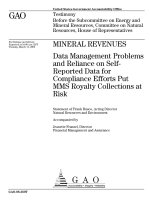
Figure 2.1 shows a flowchart illustrating various proce sses in the Suzaku obse rvation program from
GOs’ proposal submission to the da ta reception. Important issues for individual processes outlined in this
chapter are explained in more details in later chapters.
2.1 Observations Types
2.1.1 In-Orbit Checkout
The period between the launch on July 10, 2005 and the end of August, 2005 is considered the in-orbit
checkout (IOC) phase. The first part of this phase was devoted to engineering activities, and no celestial
X-ray sources were observed. After the XIS first light on August 12 and the HXD first light on August
15, observations of celestial X-ray sources were carried out. Telemetry data after August 12 are proce ssed
normally, although ca re must be taken as instrument parameters are not necessarily the same as for later
observations.
2.1.2 Observatory Time
Throughout the Suzaku mission life, approximately ∼12 % of the time will be reserved as the Observatory
Time. It will be used, for e xample, for instrumental c alibration, maintenance of the satellite, or to com-
pens ate for unexpected observational/operational failure such as cancellation of the ground contacts due
to bad wea ther. Target of opportunity (TOO) obser vations (section 2.1.6) may be also carried out using
the Observatory Time.
2.1.3 Science Working Group Time
Suzaku Science Working Group (SWG) is the collective name given to the instr ument teams, mission
operations team, software and processing team, as well as Science Advisers who were selected to provide
guidance to the Suzaku team.
During the period be tween September 2005 and March 2006, the scientific (non-Observatory Time)
observations were generally selected by, and conducted by the SWG. This period is often referred to as
the SWG phase of the mission. No new SWG observations were included into the observing program after
April 2 007, although a few SWG observations were carried out later, usually because of a problem with
the original observations. All SWG observations were completed by October 2006.
7
Suzaku PDMP v2.0 (September 27, 2007) 8
2.1.4 GO Observations
Suzaku enter e d the guest observer (GO) phase of the mission in April 2006. During this period, all non-
Observatory Time observations are selected from the world-wide astronomy community, with the exception
of the delayed SWG observations (see above). Some GO observations were carried out in February and
March 2006, before the nominal start o f the GO period.
Tar gets are selected thr ough a competitive process from observing proposals submitted by guest ob-
servers (GOs). Proposals by principal investigators (PIs) affiliated with a US institution are submitted to,
and selected by, NASA, through the annual NASA Research Announcement (NRA) process.
PIs affiliated with an institution in an ESA member country submit their propo sals through ESA, who
conduct their own proposal r e view. Proposals submitted to ISAS/JAXA (principally by Japanese PIs,
although PIs fr om non-US, non-ESA country may also apply through ISAS/JAXA) are judged by ISAS.
The ESA list is folded into the Japa nese list.
The final accepted target list is determined at the Japan-US merging meeting bas e d on the Japanese
(including ESA) and US target lists. In case there are identical targets on the Japanese and US tar get lists,
the same target may be assigned to a Japanese PI and a US PI. Such targets are referred to as “merged.”
The GOF serves as the principal point of contact for US PIs, including co -PIs of merged targets. This
includes observatio n planning, notification of availability of processed data, and support in analyzing the
processed da ta (chapter 8).
2.1.5 Calibration Observations
Suzaku team will regularly ca rry out calibration observations to monitor the performance of the instru-
ments. Calibration observations are carried out using the Observatory Time.
2.1.6 Target of Opportunity Observations
Tar gets of Opportunity (TOOs) are observations of objects or sta tes of objects that cannot be pre dicted.
X-ray novae, supernovae , strong flares of known targets, and after- glows of Gamma-ray bursts (GRBs) are
examples of TOO ta rgets.
TOO observa tions may enter the Suzaku observing program in one of two possible ways. Pre-approved
TOOs are part of the GO observations, and are limited to unpredictable phenomena on specific, known
objects. In addition, genuinely unpredictable objects or events ca n be observed as part of the Observatory
Time.
2.1.7 HXD WAM Observations
The anti-coincidence detectors of the HXD can be used to detect GRBs and to monitor the flux levels of
bright hard X-ray/γ-ray sources. This aspect of the HXD is known as the Wide-band All-sky Monitor
(WAM). Even during the GO phase, the WAM data do not belong exclusively to the PI.
2.2 Proprietary Period
The SWG data are proprietar y to the SWG until May 27, 2007, or 1 year after the date of o bs erva tion,
whichever is later. In general, GO observatio n has a proprietary period of 1 year after the delivery of the
processed data. The project may extend the propr ietary period of GO data in cases where a lack of analys is
software or calibration data seriously impacted the usefulness of the data. In s uch cases, the proprietary
period will extend 1 year after the availability of the software/calibration da ta, as judged by the project.
Calibration observations and TOO observations taken us ing the Obser vatory Time during the GO phase
have no proprietary time.
Proprietary data are ava ilable for download in encrypted form. The decryption keys are supplied to the
PIs, who may share them with their co-investigators. After the proprietary per iod is over, the decrypted
data are placed in the Suzaku archives (section 2.4.4; chapter 9), and open to all interested researchers.
Suzaku PDMP v2.0 (September 27, 2007) 9
2.3 Satellite and Instrument Monitoring
Duty scientists will monitor the health and safety of the satellite and the ins truments, both a t the downlink
station at the Uchinoura Space Center (USC) and at ISAS. They may not carry out scientific analysis of
the data. Any scientific insights incidenta lly gained by the duty scientists are considered confidential.
Certain aspe c ts of the data are cons idered non-pr oprietary. In addition to the HXD/WAM data, they
include any data during which the instruments are pointed at the Earth, and XIS data from the area of the
CCD chips dominated by the on-board calibration source. Such data can be placed in the trend archive in
unencrypted form, even during the proprietary period for that observation.
In addition, the instrumental teams may access proprietary data for the purpose of monitoring the
perfo rmance of the instruments. They must refrain from performing any scientific analysis of the data,
and keep any knowledge incidentally gained while performing their duties confidential.
2.4 Data Flow
2.4.1 Data Retrieval and Raw Data Archives
The data are retrieved from the satellite only at USC. Suzaku has the data recorder with the 6 Gbits data
capacity and can downlink the data to USC by up to ∼10 Gbits daily in 5 contact passes. Raw data are
sent fro m USC to ISAS through a dedicated network, and saved in the raw database named SIRIUS. The
SIRIUS database at ISAS stores the raw telemetry data of all the current and past ISAS missions.
2.4.2 Data Processing at ISAS and GSFC
The Suzaku data processing means conversion from the raw telemetry data to the high-level calibrated
data deliverable to the Suzaku Observers. Details of the data proces sing are explained at section 6.1, and
only an outline is given here (figure 2.1).
At ISAS, telemetry files in the SIRIUS database are wrapped into portable Raw Packet Telemetry
(RPT) FITS files, with a minimum set of FITS keywords. Routinely, ISAS will process RPT files to
produce First FITS Files, which conform to high level FITS standards.
Attitude of the satellite and the clock correction is calculated at ISAS, and the s atellite orbit is deter-
mined
1
. The First FITS Files, attitude files, orbit files and timing corr e c tion files constitute a complete
data package for each observational sequence. These packages are archived at ISAS, and the identical
copies are delivered to GSFC regularly. The RPT files are also delivered to GSFC for archival and back-up
purp oses, so that the First FITS Files may be produced at GSFC if necessary.
The sa me Pipe-line Processing runs on the First FITS Files at ISAS and GSFC, to apply the calibration
information and to produce the high-level processing products (section 6.6).
2.4.3 Data Delivery to Suzaku Observers
The processing products are delivered to the Guest Observer or the SWG members, as appropriate. US
Suzaku Observers will r e c e ive data from GSFC, and Japanese Observers will receive from ISAS. The
proprietary data are pla c e d in on the Suzaku archives with a secure data protection method such as the
PGP encryption.
Suzaku Observers will be able to conduct scientific analysis immediately from the processing pr oducts.
The analysis software and user support are pr ovided by the Suzaku GOF (see chapter 3, 4 and 8).
2.4.4 Suzaku Archives
All the Suzaku data will be delivered to and archived at the HEASARC at NASA/GSFC and to the PLAIN
Center at ISAS/JAXA. After the proprietary period is over, the data are made public (i.e., decrypted
1
In fact, the satelli te orbit is monitored at ground stations of JAXA/TKSC. JAXA/TKSC determines the Suzaku orbit,
and delivers the orbit files to ISAS regularl y.
Suzaku PDMP v2.0 (September 27, 2007) 10
version will be made available), so that archive users are able to obtain exactly the same datasets as the
original Guest Observers have received. From time to time, contents of the archives ma be updated, after
being reprocessed with up dated softwar e and c alibration files. Details of the Suzaku archives are explained
in chapter 9.
Suzaku PDMP v2.0 (September 27, 2007) 11
Satellite
USC
Orbit
Determination
(JAXA/TKSC)
Operation
Data
Acquisition
Quick
Look
Commands
ISAS
Telemetry
Database
(SIRIUS)
Merging
TOO
Observations
Commands
Data
Operation
Log
Proposal
Database
Observation
Database
GSFC
Suzaku
archives
Japanese
Guest Observers
US
Guest Observers
Calibration
Database
Operation
Center
Scheduling
Delivery
Proposal
Database
Observation
Database
Selection
in Japan
Selection
in USA
Proposals
Proposals
Mirrored
Archival
Database
Calibration
Suzaku
Team
Calibration
Database
Processed
Products
Processed
Products
Suzaku
Science Working Group
Calibration
Observations
SWG
Observations
GO
Observations
Pipe-line
Processing
Raw Packet
Telemetry
(RPT)
Attitude
Files
Orbit
Files
First FITS
Files
Attitude
Determination
FITS
Conversion
Raw Packet
Telemetry
(RPT)
FITS
Conversion
(backup)
Attitude
Files
Orbit
Files
First FITS
Files
Pipe-line
Processing
Mirrored
Figure 2.1: Overview of the Suzaku mission operation and observatio n program.
Chapter 3
Software Principles
In this chapter, we present the Suzaku software principles and agree ments, which all the software developers
need to follow throughout the Suzaku project.
3.1 General Software Design Principles
Suzaku data analysis system should share the same design principles with all the other projects conducted
under OGIP. These design principles may be summarized as follows:
1. Standard and portable data format — FITS (Flexible Image Transport System) format is adopted
for all the bina ry files. System dependent binary files will never be used. Moreover, the existing
OGIP co nventions should be followed wherever possible, and new co nventions should be submitted
to HEASARC FITS Working Group to check for consistencies with other missions. Use of ASCII
format is allowed for small files.
2. Universal and unique software — There should not be multiple channels of the data analysis. Software
releases ar e controlled, and the same routines used for the instrumental calibratio ns by hardware
teams are used for the scientific data analysis by Guest Observers.
3. Designed for multimission analysis — Existing software infrastructures will be utilized as much as
possible. Users will be able to analyze Suzaku data with standard high-level X-ray data analysis
packages such as XSPEC, XIMAGE, XRONOS, etc.
4. Easy to install and use — The so ftware will be easy to install and use, and extensive help, support
and documentation will be provided. Suzaku specific software for low-level tasks are distributed in
the standard FTOOLS package, providing user friendly interface on mo st standard platforms (section
3.3.3).
5. Free and public software — Users will not have to purchase any commercial software packages (such
as IDL), and all the sourc e codes will be open and easily available at free of charge. Users will not
have to worry about license issues, and software authors shall not claim any privileges or cr e dits.
Users may modify and distribute Suzaku software freely on their res ponsibility.
3.2 Suzaku Specific Design Principles
In addition to the general design principles above, Suzaku GOF and ISAS propose the following design
principles for the Suzaku software /data process ing system. They reflect the experiences from the ASCA
mission.
12
Suzaku PDMP v2.0 (September 27, 2007) 13
1. The raw telemetry will be converted to FITS format befo re distribution. There is only
one set of software (mk1stfits; section 6.3.1) to access and interpret the raw telemetry data and to
convert them to the FITS format (First FITS Files; section 6.3). Mk1stfits, as well as other proce ssing
software, must be fully tested and ready before the launch of the satellite.
2. All the calibration and data processing should start from the First FITS Files. To that
end, the First FITS Files should reflect the original structure of the raw telemetry as much as possible.
3. All the scientific analysi s starts from the standard calibrated FITS fil es. The First FITS
Files are further processed by the standard software with instrumental calibration information, and
the Calibrated FITS Files (section 6.3) a re produced. Scientific outputs are produced always from
the official Calibrated FITS Files, and there should not be other routes for scientific analysis.
4. The same processing system to calibrate the First FITS files should run at GSFC and
ISAS. Thereby, US a nd Japanese Suzaku Obser vers shall receive the identical Calibrated FITS Files.
5. Im portant calibration tools/software should be made promptl y available to GOs. At any
given time, there shall be always a single version of the official instrument calibration files and software
controlled by the Suzaku GOF and instrument teams. This ensures that the Suzaku Observers can
apply the latest calibration information to the observing data.
6. Suzaku software will be written by the Suzaku so ftware and hardware teams at GSFC,
ISAS and other institutions in Japan. Tasks which require deep understanding of the Suzaku
instruments, spacecra ft and telemetry formats will be mainly written by the members of the hardware
teams and ISAS. On the other hand, higher level tasks, in which user- fr ie ndliness , standardization
and confor mity with other high e nergy missions should have a high priority, will be mainly written
by the software team at GSFC.
7. All the software for public rele ase will be de livered to Suzaku GOF before the release.
Suzaku GOF will ensure that the software follow the rules presented in this chapter, and will package
them in a form which is suitable for general release. Suzaku GOF will be responsible for releasing and
mainta ining the packages. When modifications or bug fixes are necessary, the Suzaku GOF will be
responsible for the fix and the re-release, contac ting the original authors a s needed. When significant
changes are necessary, Suzaku GOF will always consult the original authors in advance.
8. Tasks required for the Pipe-line processing should run in scripts. In the automated pipe-
line processing system (section 6.6), series of data processing tasks are run as background jobs by
scripts. Therefore, all the processing tas ks including those which make use of GUI are required to
run in scripts.
3.3 Suzaku Software Standards
3.3.1 Languages
Suzaku softwar e will be mainly written in C. The use of C++ is allowed, but not encoura ged. C ++ will
not be adopted throughout the project, but may be used within some small independent packages (e.g.,
ray-tracing program). Fortran77 is allowed, but Fortran90 sha ll not be used.
In the scripting tasks , use of system independent environments such as Perl or Tcl/Tk is recommended.
Use of the shell languages (such as csh, bsh and tcsh) which do not run beside UNIX environment is
forbidden.
Suzaku PDMP v2.0 (September 27, 2007) 14
3.3.2 Coding Rules and Compiler Requirements
Portable coding prac tices shall be adhered to, including the isolation of system dependencies. C programs
will adhere to the ANSI C standard, while Fortran programs will follow the OGIP Fortran standards
(Mukai 1993)
1
for Fortran programming.
The system-independence test for C shall be that the code can be compiled by gcc on the several
supported architectures (see section 3.3.3); similarly g77 will be used to test Fortran programs. The
cfortran package shall be used to combine C and Fo rtran routines when necessary.
To write and read FITS files, cfitsio (in C) or fitsio (in Fortran) should be use d. The obsolete fitsio
C-wrappers, which were developed to call for tran fitsio routines from C-codes, should not be used.
3.3.3 Systems Supported
All the Suzaku software intended to distribute shall run on the most popular systems of Suzaku users. The
systems are likely to include Sun/ Solaris, DEC/Alpha, Linux (Redhat, Power PC), and Apple/Darwin
(Mac-OS X).
3.3.4 Coordination and Version Control
The So ftware Coordination Group consisting of members fro m each hardware team, ISAS, and the GOF
shall meet regularly (at least twice a year until and soon after the launch) to ensure softwar e coordinations.
In addition, the GOF shall have one person attached to each hardware team with responsibility to help
coordinate software development. The software c oordination group shall also be responsible for ensuring
consistency of FITS keyword naming acro ss teams.
The 1st Stage Software (section 6.3) is maintained by I SAS. GSFC keep master copies of all the software
except the 1st Stage Software under a control system. This control system shall ensure that a given file
is only edited by one per son at a time and also that previous versions are archived and can be recovered.
The practical way that Suzaku FTOOLS will be developed and maintained globally is explained in section
3.4.
3.3.5 Documentation
All software intended for distribution should be fully documented in English. Comments in the source
codes should be written in Eng lis h, but Japanese translation might be added for convenience and may not
have to be stripp e d when distributed.
All subroutines/programs of general use sha ll contain a standard header. The GOF will provide a script
to s trip out these headers and make them available over the Web. The GOF will also provide template
routines containing the standard header.
The FITS file forma t of Suzaku related files is fully explained in a separate document maintained by
the Suzaku GOF.
3.4 Suzaku FTOOLS Global Development Scheme
Many scientists and programmer s in the United States and Japan a re involved in the Suzaku FTOOLS
development. Also, Suzaku FTOOLS users are located not only in the two countries, but also in Europe
and the rest of the world. Therefore, version control will b e very important so that no different flavors of
the same FTOOLS be developed and proliferated.
In the ear ly stage of the mission, as under standing of the instruments deepens and new data analysis
techniques are getting established, it will be necessary to update and release the Suzaku FTOO LS promptly.
We should be re ady for the release cycle of a few weeks or less.
1
See />fortran3.html. This is ANSI Fortran77 with some extensions.
The extension includes the following: (1) Both upper and lower case letter are allowed. (2) END DO are all owed. (3) DO
WHILE loops are allowed. (4) INCLUDE statements are al lowed. (5) INTEGER*2 data type is allowed. (6) Variable can be
up to 31 character long. (7) IMPLICIT NONE is allowed.
Suzaku PDMP v2.0 (September 27, 2007) 15
ISAS
Repository
Ftools
team
Develop
Ftools
GOF
Build
weekly
Test
Test
GSFC
Build
Suzaku ftools
as needed
Official
ftools release
(once or twice a
year)
Mirrored
Daily
Suzaku
Users in US
and Europe
Release
Ftools
Suzaku
add-on
Release
Ftools
Suzaku
add-on
HXD team
XIS team
Software
Development
Coordinator
Deliver
new codes
Check
Consistency
Test
Test
Suzaku
Users
Suzaku
Users
Suzaku
Users in Japan
Used
for
analysis
Used
for
analysis
ftp
Processing
Center
Mirrored
as needed
anonymous
ftp
anonymous
ftp
Processing
Ftools
pipe-line
processing
system
Processing
Ftools
pipe-line
processing
system
Software
Development
Coordinator
Figure 3.1: Suzaku FTO OLS glo bal development and version control s cheme.
To accommodate both requirements of the rigorous version control and prompt release, the fo llowing
scheme, which is illustrated in figure 3.1, ha s been proposed and will be practiced for the Suzaku FTOOLS
development, version control, and release .
1. At GSFC, the FTOOLS team maintains the FTOOLS “Repository”, for which only the team mem-
bers ar e granted the write p e rmission. The FTOOLS team receives or iginal source codes from the
“Contact” groups (throug h ISAS when the Contact groups are in Japan; see 6 below), and put
the codes in the Repository, after minimal programmatic changes if necessary. The codes in the
Repository should be considered the genuine copy of the latest official FTOOLS.
2. The entire FTOOLS directory tree is built weekly from the Rep ository. This FTOOLS is called
“Develop” FTOOLS, and only available inside GSFC. The Develop FTOOLS are tested at GSFC,
and the codes will be fixed if any problems are found, and put in the Repository again. Note that
the Develop FTOOLS reflect updates of all the FTOOLS including Suzaku.
3. From time to time, the entire FTOOLS package is released to public. This package is ca lled the
“Release” FTOOLS. Frequency of the release is typically once or twice a year.
Suzaku PDMP v2.0 (September 27, 2007) 16
4. In order to keep up with short development cycle, whenever Suzaku FTOOLS in the Repository
are updated, the FTOOLS team will build the Suzaku FTOOLS against the Release FTO OLS, a nd
install the “Suzaku add-on”. Interval of the Suzaku add-on build will be as short as one week (=
Develop FTOOLS build cycle). The Release FTOOLS with the Suzaku add-on is the one Suzaku
users will use for their data analysis. The Suzaku add-on package will be promptly released to Suzaku
users, so tha t they can install it on their own Release FTOOLS.
5. The Release FTOOLS with the Suzaku add-on will be mirrored daily to ISAS, and will be used
for Suzaku data analysis a t ISAS. Japanese Suzaku users outside of ISAS may obtain the original
package from GSFC or mirrored one from ISAS.
6. Instrument teams in Japan will test and modify the source codes in the Suzaku add-on package
to reflect the latest calibration, and they will deliver the new codes to the Software Development
Coordinator at ISAS. The Software Development Coordinator will make sure that the codes from
different groups are consistent and can be built cleanly using gcc. After that, he o r she will deliver
the codes to the FTOOLS team at GSFC (go back to step 1).
7. The Processing team at GSFC will obtain the Release FTOOLS with the Suzaku add-on, which
will become the base of the pipe-line processing. The Processing FTOOLS, as well as the pipe-line
processing scripts, will be mirrored to the ISAS processing ce nter from GSFC, so tha t the data centers
at GSFC and ISAS use the identical system to produce standard Suzaku data products.
8. The processing software sho uld be built-in the software packages HEAsoft, and the processing should
be performed with the the latest release (ver. 6.0.3 in November 2005).
3.5 Suzaku Ftools Release Plan
1. Ftools delivery should include .par files, .hlp files and unit test scripts following the templates provided
by HEASARC.
2. Freeze dates of the Suzaku ftools on the GSFC CVS are the last days of January, April, July and
October. After the freeze, only bug fixes may be committed to the CVS .
3. After the freeze dates, Suzaku ftools go through the multi-platform test at GSFC and I SAS, which
takes maximum six weeks.
4. After the multi-platform test, Suzaku ftools release will be around March 15, J une 15, September 15,
and December 15. These r e le ase dates may be slightly shifted being affected by situations of other
ftools development/release, because it is desirable that Suzaku ftools release be synchronized with
other ftools releas e as much as possible.
5. After the release, new ftools, libraries or new functionalities may be committed to the GSFC CVS.
Going back to 1 above, the next release cycle starts.
Chapter 4
Suzaku Function Libraries
There will be software mo dules that are used repeatedly in various sta ges of the Suzaku mission, fr om the
satellite operation to the scientific data analy sis. In order to avo id overhead and inconsistency, functions
supposed to be used by two or more tools will be included in the Suzaku function libraries.
There will be at le ast three such function libra ries for Suzaku; aste
tool, which includes functions fo r
Suzaku specific tasks, atFunctions, which includes functions for generic attitude and orbita l related tasks
1
,
and xrrt, which is fo r XRT ray-tracing. They are implemented in the FTOOL S package as libastetool.a,
libatFunctions.a, libxrrt.a, respectively
2
.
4.1 Suzaku Specific Tasks (aste
tool)
4.1.1 Time Conversion
Routines to carry out conversion between Suzaku time and other time systems will be necessary. Suzaku
time will be defined as the elapsed time from the beginning of year 2000 in UTC. The leap second table is
referenced to take into account the leap seconds.
4.1.2 Coordinate Conversion
Since the XIS is an imaging instrument, coordinate s ystems for XIS images are must be defined. Functions
to carry out conversio n between these coordinates will be necessary (e.g., when making observation plans
and calibrating FITS event files), and will be included in aste
tool.
4.1.3 Energy Calibration
Suzaku instruments measure X-ray photon energy as pulse heights; the raw measurements are referred to
as the Pulse Height Analyzer (PHA) channels. Although PHA values are roughly proportional to the input
energies, they vary with several conditions such as time, location on the detector, temperature, etc. After
correcting these effects, we may define Pulse Invariant (PI), which should be perfectly proportional to the
energy.
We will need to calculate PI from PHA for all the three instruments to fill the PI columns in the event
FITS files (section 6.4). The ro utines to calculate PI from PHA shall be included in aste
tool. These
routines need to access calibration files to get calibration information (chapter 7).
1
atFunctions has been used al so for ASCA.
2
On the Unix platforms. For other platforms, the names will be different.
17
Suzaku PDMP v2.0 (September 27, 2007) 18
4.1.4 HK Information Acquisition
All satellite and instrument housekeeping (HK) parameters are stored in the HK FITS files (sectio ns 2.4.2
and 6.3), which can become huge. However, only a small fraction of the HK parameters will be actually
required for sc ie ntific da ta processing. In order to facilitate the use of HK files, HK file access routines
shall be provided in aste
tool. Note that HK access routines need to be built with efficiency in mind.
HK parameters in the telemetry a re digitized at discrete intervals, thus aste
tool routines may have
to convert them to physical values, and interpolate or smooth them as needed. For example, we may
require an aste tool routine which gives instrument temperatures in degrees continuously by interpolating
discretely measured temperatures in digitized units.
Parameters for conversion from the digitized HK telemetry to the physical units are stored in the
multimission database named Satellite Information Base (SIB) located at ISAS. Although SIB itself is not
portable, Suzaku related information in SIB will be necessary to inter pret HK parameters in the telemetry.
Therefore, essential parts of the SIB will be extracted and put in the calibration files (section 7.4.1).
4.1.5 Other Tasks
Functions for other tasks will be included in aste
tool as needed. For example, a random number generation
function will be required so that the same sequence of random numbers are always obtained from the same
seed.
4.2 Attitude and Orbit Related Tasks (atFunctions)
The attitude and orbit related functions in atFunctions will be used in va rious purposes such as; command
planning, assignment of SKY coordinates to events (section 6.4), creation the Filter files (section 6.4.1),
calculation of the e xposure maps, and barycentric corr ections (section 6.5.3). They may require the attitude
files, the orbit files, or both (section 6.2). The following are examples of the tasks in atFunctions.
4.2.1 Attitude Information
• Obtain q-parameter s and/or Euler angles fo r a given time.
• Determine the pointing direction of each telescope/sensor for a given time.
4.2.2 Orbit Information
• Obtain satellite orbital position for a given time.
• Obtain magnetic cut-off rigidity for a given time.
• Determine if the satellite is in day (sun-lit) or dark (not sun-lit) for a give time. Also obtain the
elapsed time after the last day-to-dark or dark-to-day transition.
• Determine if the satellite is in the South Atlantic Anomaly (SAA) or not for a given time. Also
obtain the elapsed time after the last SAA passage.
• Obtain sidereal direction of the magnetic field line for a given time.
4.2.3 Attitude and Orbit Information
• Output the angles from the earth rim and sun-lit part of the earth for a given time.
• Determine if the pointing direction is blocked by ea rth or not. If it is, deter mine if the earth is sun-lit
or not.
Suzaku PDMP v2.0 (September 27, 2007) 19
4.3 Ray-Tracing Function Library (xrrt)
The Suzaku ray-tracing package named xrrt ha s been written in C++, and is available as a function
library. This library provides function to load mirror, obstruction, and reflec tion tables from FITS files,
and then to trace photo ns through the mirr or sets and collect statistics about the results. See section 5.2.3
for detail.
Chapter 5
Planning and Simulation Software
In this chapter, Suzaku software used for observation planning and simulation are explained.
5.1 Observation Planning Software
5.1.1 TAKO (Timeline Assembler, Keyword Oriented)
A planning software package named “TAKO” (for Timeline Assembler, Keyword Oriented) is developed
for Suzaku by GSFC ba sed on the methods used for ASCA and XTE.
This package is designed to accommodate Suzaku specific constraints. These constraints are determined
in cooperation of ISAS and GSFC instrument and operations teams. Post-launch changes will be handled
in a similar fashion. As has been the case for ASCA, a technician is employed by GSFC and stationed at
ISAS to maintain and operate TAKO to produce regular observation schedules.
5.1.2 MAKI
MAKI is developed at GSFC for Suzaku and future multimission pla nning
1
. Users may run MAKI through
a Web browser (users will need to obtain and install the “LHEA Plug-In”
2
). Users may place different
satellite fields of view on a sky image to plan out observation (Euler angles are automatically calculated).
These FOVs may be rota ted, and MAKI will indicate if the roll is allowed or not by different colors for a
given time period. Users ca n also view the sun angle vis ibility limits for several missio ns, as well as adding
phase constr aints. MAKI is expected to replace the ASCA command planning program “a dcongra” which
had similar but more primitive functions.
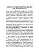
MAKI accepts a sky image file from “SkyView”
3
, or almost any FITS image files. It also lets users save
and reload the results. In figure 5.1, an example of MAKI output is shown.
5.2 Simulation Software
Suzaku simulation so ftware will have the following purposes. First, simulation software will be used to
study technical feasibility of planned obse rvatio ns. Second, they will be used to determine instrumental
responses in order to simulate and understand physical processes in the instruments. Third, they may be
used in data analysis when ins trument responses are difficult to determine and Monte Carlo approach is
1
See the MAKI home page for detail.
2
The LHEA Plug-In is developed at LHEA at N ASA/GSFC. It is a web plug-in that lets users use interactive astronomy
tools via the simple interface of users’ browser.
3
SkyView is a “Virtual Observatory” on the Net generating images of any part of the sky at wavelengths in all regim es from
Radio to Gamma-Ray. See for details. MAKI can launch from the SkyVi ew
output page if “Advanced” interface is selected.
20
Suzaku PDMP v2.0 (September 27, 2007) 21
Figure 5.1: An examples of the MAK I plot. An XRS field of view is displayed on an optical image obta ined
from SkyView.
considered more effective. Finally, simulated data sets will be used to verify software for data analysis and
processing.
5.2.1 Counting Rate Simulation – PIMMS
When planning observatio ns , the first thing needed is to estimate the expected counting rates . For such
a purpose, PIMMS (Portable, Interactive, Multi-Mission Simulator) has been developed at GSFC and
already widely used in the community. Users will be able to estimate the expected counting rates for XIS
and HXD by inputting the source flux and the spectral form. The source flux can be a physical unit (ergs
s
−1
cm
−2
) or counting rates from other satellites/instruments.
As of ver. 3.6 released in late 2004, PIMMS calculates expected counting rates for Suzaku. See details
at
/>4
.
5.2.2 Spectral Simulation – XSP EC
The XSPEC spectral fitting package has the capa bility to simulate instrument dep e ndent pulse-height
sp e c tra for given input photon spectra
5
. To that end, XSPEC requires not only the e ffective area and
efficiency (ARFs – Ancillary Response Files), but also the response matrices (RMF – Redistribution Matrix
Files).
4
The WWW vers ion of PIMMS, WebPIMMS is also devel oped and available at
/>5
The WWW vers ion of the XSPEC spectral simulation, WebSpec, is available at
/>Suzaku PDMP v2.0 (September 27, 2007) 22
GOF has released a suite of the Suzaku response functions for spectral simulation purposes. See,
/>prop tools.html for details.
5.2.3 XRT Ray-Tracing Library – libxrrt
The ray-tracing package, named “xrrt”, was developed at GSFC ADF (Astrophysics Data Facility) in
cooperation with ISAS, Nagoya University and GSFC mirror team (code 662). The package is written in
C++. It is available as a function librar y (section 4.3) for use by other FTOOLS such as xissim.
The ray-tracing package will be used to determine physica l parameters of the mirrors which are difficult
to measure (e.g., surface densities), by compa ring the actual da ta and simulations. XRT responses such
as p oint spread functions and effective areas will be determined through iterations of the ray-tracing
simula tions and actual calibration data.
The ray tracing package is also useful to simulate obse rvations when making plans or analyzing data.
For exa mple, if there are bright sources outside of the field of view, amounts of the s tray-lights can be
estimated through the ray- tracing simulations.
5.2.4 Suzaku XIS Event Simulator xissim
A simple simulation with XSPEC does not work in estimating contamination from nearby sources or
a position dependent spectrum of extended sources, coupled with the image qua lity. Such estimates are
sometimes necessary for pr oposing new Suzaku obse rvatio ns or comparing the observing data with the faked
data of a complicated model through Monte Carlo simulations. The instrument team has developed the
photon-by-photon simulator of XIS events, xissim
6
. The simulator is comprise o f two tasks: mkphlist,
which fakes incident photons from celestial sources in the XIS FOV, and xissim, which simulates XIS
events of the faked photons, tak ing into account the XRT efficiency and the XIS response. The software
outputs photon e vent files as the real o bserving data, so uses can analyze the simulated data with the
generic XANADU software.
6
the xissim software package can be downloaded from />tools/xissi m/xissim usage.html
Chapter 6
Data Analysis and Process ing
Software
In this chapter, we define and explain Suzaku software tasks that are used for the data processing at ISAS
and GSFC and for the data analysis by Suzaku observers. The naming conventions of product files and
directory structures can be found in more detail in the Interface Control Document (ICD)
1
.
6.1 Overview
In figure 6.1, we provide an overview of the Suzaku data flow, which we divide into four stages: satellite
sp e c ific calibratio n (Stage 0), production of the First FITS files (Stage 1), ins trument specific calibration
(Stage 2) and data analysis (Stage 3).
In general, so ftware tools used in the earlier stages (Stage 0, 1) do not nee d to be portable since they
run only at ISAS and/or GSFC, but they must be stable so that data need not be run through these stag e s
repeatedly. On the other hand, software used in the later stages (Stage 2, 3) must be portable and flexible
since they are distributed to Suzaku users for data ana ly sis and for reprocessing when new calibration
information becomes available. All distributable Suzaku software are built and distributed within the
FTOOLS package (table 6.3 for a full list).
6.2 Stage 0 – Satellite S pecific Calibration
In this stage, the Suzaku team at ISAS collects the orbital information, processes satellite specific cal-
ibration, and converts satellite raw telemetry data and satellite specific information to the Raw Packet
Telemetry (RPT) files, attitude FITS and orbital FITS files. The o utput RPS files a re regularly copied to
the database at GSFC as back-up (figures 2.1, 6.1 and 6.2 ).
6.2.1 Orbit Determination
JAXA/TKSC determines the Suzaku orbit and sends the data regularly to ISAS. The data are converted
to FITS format, containing both the orbital elements as well as explicit satellite positions as a function of
time during the relevant period.
6.2.2 Attitude Determination
The NE C /Toshiba space system develops the attitude determination software as for the GINGA and
ASCA satellites. ISAS hires technicians who will work full-time on the attitude determination. The
Suzaku attitude files have the same FITS format as the ASCA attitude files.
1
e
icd sdc v1.2.pdf
23