Cài đặt biến tần Wobao WB620
Bạn đang xem bản rút gọn của tài liệu. Xem và tải ngay bản đầy đủ của tài liệu tại đây (241.92 KB, 10 trang )
Người báo cáo:
Nguyễn Minh Hiếu
Tài liệu:
Hướng dẫn cơ bản WB620
Ngày:
24/10/2022
Trang:
1
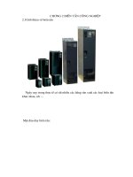
HƯỚNG DẪN SỬ DỤNG CƠ BẢN BIẾN TẦN WOBAO
WB620
Người báo cáo:
Nguyễn Minh Hiếu
Tài liệu:
Hướng dẫn cơ bản WB620
Ngày:
24/10/2022
Trang:
2
I. HƯỚNG DẪN ĐẤU NỐI BIẾN TẦN:
Sơ đồ đấu nối biến tần WB620
Người báo cáo:
Nguyễn Minh Hiếu
Tài liệu:
Hướng dẫn cơ bản WB620
Ngày:
24/10/2022
Trang:
3
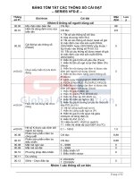
II. HƯỚNG DẪN CÀI ĐẶT BIẾN TẦN:
1. CÀI ĐẶT BIẾN TẦN CƠ BẢN:
Thông
Chức năng
Giá trị
số
01110
P01
Cài đặt tham số
02220
11111
0
1
P02
Lệnh chạy
2
4
Bảo vệ khi mở nguồn
0
P318
chế độ chạy bằng tiếp
1
điểm bên ngoài
0
1
P03
Lệnh tần số
2
4
1
Lựa chọn bộ nhớ khi
2
P842
tắt nguồn
3
0
1
P04
Chế độ chạy
2
P06 ~
Tần số tối đa
P05
650Hz
Tần số tối đa khi dùng
0.1~650.0Hz
P202
Fv
Tần số tối thiểu
0.00 ~ P05
P06
Thời gian tăng tốc
0.1 ~ 6000.0
P07
Thời gian giảm tốc
0.1 ~ 6000.0
P08
0
P20
Phương pháp dừng
1
Cài chức năng X1
0
P301
Cài chức năng X2
1
P302
Cài chức năng X3
2
P303
Cài chức năng X4
3
P304
Cài chức năng X5
6
P304
Cài chức năng X6
11
P305
12
YO JA1.JA2.JA3
7
P340
Y1 output terminal
14
P341
Mô tả
Khôi phục các tham số chức năng về nhà sản xuất
Khôi phục thông số động cơ về nhà sản xuất
Khôi phục tất cả các thông số về nhà sản xuất
Bàn phím
Tiếp điểm bên ngồi
Nhiều cấp tốc độ
RS485
Cho phép chạy khi mở nguồn
Không cho phép chạy khi mở nguồn
Bàn phím
Biến trở màn hình
Analog bên ngồi (biến trở, cảm biến)
RS485
Tần số bàn phím
Tần số RS485
Tần số bàn phím + RS485
Chế độ V/f
Chế độ V/f có bù torque
Chế độ sensorless vector
Mặc định 50Hz
Mặc định 50Hz
Mặc định 0.0Hz
Mặc định 10s
Mặc định 10s
Dừng theo thời gian giảm tốc
Dừng tự do
Không chức năng
Lệnh chạy thuận
Lệnh chạy nghịch
Lệnh dừng
Lệnh jog
Đa cấp tốc độ 1
Đa cấp tốc độ 2
Đang chạy mode 1
Đang cảnh báo
Người báo cáo:
Nguyễn Minh Hiếu
Tài liệu:
Hướng dẫn cơ bản WB620
Ngày:
24/10/2022
Trang:
4
2. HƯỚNG CÀI ĐẶT TRUYỀN THƠNG (RS485) CỦA BIẾN TẦN:
Thơng
số
P02
P03
Chức năng
Giá trị
Lệnh chạy
Lệnh tần số
4
4
0
1
2
3
1-247
3
4
5
0
1
2
3
4
5
0
1
0
P600
Lựa chọn chức năng
giao tiếp
P601
Địa chỉ Slave
P602
RS485 baud rate
P603
RS485
định dạng dữ liệu
P604
Kiểm tra mã vị trí
khung truyền RS485
P605
RS485
chế độ trả lời
P606
P607
RS485
communication
thời gian trễ
RS485
communication
timeout
1
Mô tả
Modbus điều khiển (Run).
Điều khiển tần số bằng Modbus.
Vơ hiệu hóa chức năng giao tiếp
Chế độ chỉ đọc (không cho phép ghi).
Chế độ đọc ghi (tham số ghi 1 không hợp lệ)
Chế độ đọc ghi (tham số ghi 2 hợp lệ)
1
9600 bps
19200 bps
34800 bps
8N1 (8-bit data, 1-bit stop, no parity)
8E1 (8-bit data, 1-bit stop, no parity)
801 (8-bit data, 1-bit stop, odd parity)
8N2 (8-bit data. 2-bit stop, no parity)
8E2 (8-bit data, 2-bit stop, even parity)
802 (8-bit data. 2-bit stop, odd parity)
Mã thấp trước
Mã cao trước
Không trả lời lệnh ghi từ master
Trả lời lệnh ghi từ master
Chú ý: Không ảnh hưởng trên lệnh đọc từ master.
P605 = 0 có thể cải thiện hiệu suất truyền thơng.
5~100
ms
Chú ý: sau khi Slave nhận dữ liệu, sau khoảng thời gian cài
đặt bởi thông số này sẽ trả dữ liệu về master.
Ví dụ: khi tốc độ giao tiếp của master khơng đủ do lỗi giao
tiếp, bạn có thể tăng giá trị cài đặt để đáp ứng khả năng
tương thích.
0.0~999.0
ms
Lưu ý: Khi [P-600] được cài hợp lệ, Slave sẽ tự dừng lại
khi nó khơng nhận được dữ liệu định dạng chính xác trong
thời gian được thiết lập bởi tham số này. Đã báo lỗi "CE".
Khi này
tham số được đặt thành 0.0S, chức năng phát hiện thời gian
chờ được tắt.
Người báo cáo:
Nguyễn Minh Hiếu
Tài liệu:
Hướng dẫn cơ bản WB620
Ngày:
24/10/2022
Trang:
5
Chapter VII Fault Definition and Troubleshooting
error
code
Fault type
UV1
DC bus low voltage
UV2
| Contactor pull-in
failure
OV
DC bus overvoltage
EOV
Overvoltage protection
circuit is abnormal
Possible cause of failure
malfunction
Low grid voltage
Check grid input power
Inverter internal fault
Seeking service
Contactor failure
Please replace the contactor
High grid voltage
Check grid input power
Inverter internal fault
Seeking service
Overvoltage protection circuit is abnormal
Please check the overvoltage
protection circuit
Seeking service
Acceleration too fast
Increase acceleration time
Low grid voltage
Check the input power
Inverter power is too small
Select a higher power inverter
Deceleration too fast
Increase deceleration time
Large load inertia torque
Plus suitable energy-consuming
brake components
Inverter power is too small
Select a higher power inverter
Sudden or abnormal load
Check for sudden changes in load
or light load
Low grid voltage
Check the input power
Inverter power is too small
Select a higher power inverter
Output short
Check if the motor and wiring are
well insulated
accelerate
slow
down
OC
Output overcurrent
Constant
speed
OC failure cause
accelerate
OCV
Overcurrent and
overvoltage
slow
down
OC failure countermeasures
Abnormal input voltage
Check the input power
After a momentary power failure,
restart the rotating motor
Avoid downtime and restart
Deceleration too fast
Reduce deceleration time
Large load inertia
Increase energy consumption
brake assembly
Người báo cáo:
Nguyễn Minh Hiếu
Tài liệu:
Hướng dẫn cơ bản WB620
Ngày:
24/10/2022
Trang:
6
Constant
speed
GF
Err
Output ground fault
Hardware protection
circuit is abnormal
Abnormal input voltage
Check the input power
Abnormal changes in input
voltage
Install input reactor
Large load inertia
Plus suitable energy-consuming
brake components
Wiring error
Correct the wiring error according
to the manual
Motor abnormal
To replace the motor, you need to
perform an insulation test on the
ground first.
Inverter module is abnormal
Seeking service
Excessive leakage current to ground at the
output side of the inverter
Seeking service
Power grid fluctuations or momentary power
outages
Check local power supply
Hardware protection module is abnormal
Seeking service
Grid voltage is too low.
Check grid voltage
Motor rated current setting is incorrect.
OL1
OL2
SPi
Motor overload
Reset motor rated current
Motor stalled or sudden load change
Check the load and adjust the
torque boost
Motor power does not match
Choose the right motor
Acceleration too fast
Increase acceleration time
Restarting a rotating motor
Avoid downtime and restart
Grid voltage is too low
Check grid voltage
Excessive load
Choose a more powerful inverter
Inverter power terminal wiring is abnormal,
missing or disconnected
Check the power supply wiring
according to the operating
procedures to eliminate missing
connections and broken wires.
Severe imbalance of three-phase input power
Check whether the three-phase
imbalance of the input power
meets the requirements
Inverter capacitor aging
Seeking service
Abnormal circuit during inverter power-on
Seeking service
Inverter overload
Input phase loss
Người báo cáo:
Nguyễn Minh Hiếu
Tài liệu:
Hướng dẫn cơ bản WB620
Ngày:
24/10/2022
Trang:
7
SPo
Severe imbalance in output three phases
Check if the motor is intact, check
if the characteristics of the
terminals on the output side of the
inverter and the DC side are
consistent when the power is off
Inverter output side wiring is abnormal,
missed | or broken
Check the wiring on the output
side according to the operating
procedures, eliminate missing
connections and broken wires
Output phase loss
PUF
Fast-Acting Open
Circuit Failure
Fast-acting open circuit abnormal
Seeking service
LH1
Radiator low
temperature
The radiator module is abnormal
Seeking service
U-phase zero current
deviation
Three-phase imbalance
Check output side wiring
CT1
Broken current detection circuit
Seeking service
Three-phase imbalance
Check output side wiring
Broken current detection circuit
Seeking service
CT2
V-phase zero current
deviation
W-phase zero current
deviation
Three-phase imbalance
Check output side wiring
Broken current detection circuit
Seeking service
EF1
External input fault 1
External fault input terminal action
Check external device input
EF2
External input fault 2
External fault input terminal action
Check external device input
EF3
External input fault 3
External fault input terminal action
Check external device input
EF4
External input fault 4
External fault input terminal action
Check external device input
PID feedback disconnected
Check PID feedback signal cable
PID
PID disconnection fault
PID feedback source disappears
Check PID feedback source
Incorrect baud rate setting
Set the appropriate baud rate
Communication error using serial
communicatio
Press STOP to reset and seek
service
Long communication interruption
Check communication interface
wiring
Braking unit power is too small
Increase the braking unit power
Load exceeds braking capacity
Increase braking load capacity
Braking due to dust and other reasons
Eliminate external interference
factors
CT3
CE
Brr
Communication timeout
failure
Brake unit failure
Người báo cáo:
Nguyễn Minh Hiếu
Tài liệu:
Hướng dẫn cơ bản WB620
Ngày:
24/10/2022
Trang:
8
SC
OH2
Output short-circuit fault
Radiator overheating
Internal short circuit damage caused by
conductive dust
Seeking service
Wiring error
Correct the wiring error according
to the manual
Motor abnormal
To replace the motor, you need to
perform an insulation test on the
ground first.
Inverter module is abnormal
Seeking service
Excessive leakage current to ground at the
output side of the inverter
Seeking service
Power grid fluctuations or momentary power
outages
Check local power supply
Ambient temperature is too high
Reduce ambient temperature and
strengthen ventilation
Air duct blocked
Clean up dust, cotton wool and
other debris
Fan abnormal
Check if the fan power cable is
connected properly
Replace the fan of the same model
Inverter module is abnormal
Seeking service
Temperature detection circuit failure
Seeking service
TF1
Self-learning failure 1
Motor wiring is abnormal
Check motor wiring and
parameter settings
TF2
Self-learning failure 2
The self-learned parameter has a large
deviation from the standard parameter
Leave the motor unloaded and reidentify
TF3
Self-study failure 3
Improper motor rated parameter setting
Set the rated parameters according
to the motor nameplate
Người báo cáo:
Nguyễn Minh Hiếu
Tài liệu:
Hướng dẫn cơ bản WB620
Ngày:
24/10/2022
Trang:
9
Chapter VIII RS485 communication protocol (including
examples)
Register address
HO000
03DEH
Register address
1000H control frequency
The following restrictions
apply: when the operation
command mode is set to
communication control (P002 = 4) (P-012 = 4)
2000H
2001H
Meaning of data
Read and write internal function
parameters [P-000] ~ [P-F30]. The
communication address is:
(parameter group number 64) +
parameter number. For example: [P610] The communication address is:
(6 * 64) + 10, which is equal to 394
(decimal) and 018A (hexadecimal).
Note: You can also directly check
the communication address column
in the parameter summary table.
Meaning of data
Forward running
0001H
instruction
0002H
Reverse run command
Forward and reverse
0003H
switching instructions
0004H
Reserved, write invalid
Deceleration stop
0005H
command
0006H
Free stop instruction
Fault reset command
0007H
(Note: no limit of running
command)
0008H
Reserved, write invalid
Emergency stop
0009H
instruction
RS485 communication frequency. Note: When power
on, the data value is [P-610] setting value. Note: The
maximum allowable set value of this data corresponds
to the set value of the output upper limit frequency [P005]. When it exceeds, the data may overflow (Note:
RAM type data)
Communication setting PID value. Note: When power
on, the value of this data is 0.00. Note: The maximum
allowable setting value and physical meaning of this
data correspond to the setting value of the feedback
sensor range [P-704]. (Note: RAM type data)
Read and write
Readable
(03H)
Box back (06H)
(86H)
Read and write
Write Only (H90) (86H)
Read / write (03H) (196),
(H98)
Read / write(03H) (196),
(H98)
Người báo cáo:
Nguyễn Quang Minh Tiến
Tài liệu:
Hướng dẫn cơ bản WB620
Ngày:
24/12/2019
Trang:
10
Register address
Meaning of data
B3-b0
3000H
Inverter running
status
B4
06H (fixed command
code)
Running status
(Note: 0-8)
0-8 running
direction (Note: 0 is
forward)
B7-5
B13-8
3001H
3002H
3003H
3004H
3005H
3006H
3007H
3008H
3009H
300AH
300BH
300CH
300DH
300EH
300FH
3010H
3011H
3012H
3013H
3014H
3015H
3016H-301FH
Read and write
Fault number (Note,
0 ~ 47)
Reserve
B15-14
Inverter setting frequency
Inverter output frequency
Inverter output current
Inverter output voltage
DC bus voltage
Motor output power (Note: signed 16 bits)
Motor running speed
Motor electromagnetic torque (Note: signed 16 bits)
Radiator temperature
0 when reserved read
FV input terminal analog value
FI input terminal analog value
PID given value
PID feedback value
Xn digital input terminal status
Yn digital output terminal status
Multi-speed current number of segments (Note: 0 ~ 15)
PLC current segment number (Note: 0 ~ 15)
PLC has cycled
PLC has been running at this stage
PLC has stopped at this stage
Reserved. Returns 0 when read
5001H (fixed address)
0000H: No fault
0001H: Reserved
(password locked)
0002H: Incorrect
command code
0003H: The number of
read data is wrong
0004H: illegal address
0005H: Illegal data
0006H: Invalid parameter
change
0007H: System is locked
0008H: inverter is busy
(EEPROM is being
stored)
Read-only (H3)
Automatic response