CCIE ROUTING SWITCHING
Bạn đang xem bản rút gọn của tài liệu. Xem và tải ngay bản đầy đủ của tài liệu tại đây (1.86 MB, 338 trang )
CCIE ROUTING & SWITCHING
www.MicronicsTraining.com
Narbik Kocharians
CCIE #12410
R&S, Security, SP
3550/3560
Answers
CCIE R&S by Narbik Kocharians
FREE Labs Page 1 of 338
© 2007 Narbik Kocharians. All rights reserved
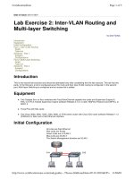
Router To Switch connection
CAT1
CAT2
R1
F0/1
F0/1
F0/0 F0/1
R2
F0/2
F0/2
F0/0 F0/1
R3
R3 F0/3
F0/3
F0/0
F0/1
R4
F0/4
F0/0 F0/1
F0/4
R5
F0/5
F0/5
F0/0 F0/1
R6
F0/6
F0/6
F0/0
CCIE R&S by Narbik Kocharians
F0/1
FREE Labs Page 2 of 338
© 2007 Narbik Kocharians. All rights reserved
CAT1
CAT2
F0/20
F0/19
F0/22 F0/21
F0/21 F0/22
F0/19
F0/20
SW3
SW4
CAT1
SW4
F0/7
F0/8
CAT2
SW3
F0/7
F0/8
CCIE R&S by Narbik Kocharians
FREE Labs Page 3 of 338
© 2007 Narbik Kocharians. All rights reserved
Lab 1
Basic 3560 configuration I
Task 1
Configure the first and the second switch to be in VTP domain called CCIE
Before assigning a VTP domain name, there must be a trunk established between
the two switches so the configurations will be propagated to the other switch.
On both switches
Switch#Show interface trunk
Switch#
Note the two 3560s switches are connected with 2 cross over ethernet cables, if these
switches were 3550s, the two ports would have negotiated an ISL trunk, actually
they would show up as “nisl”, this is because by default the ports were configured
in desirable mode. With 3560 switches, the ports are not in desirable mode, a “show
run int f0/19” will reveal this information, and therefore, the port/s must be
configured statically to trunk or negotiate a trunk.
On Both switches:
Switch#Show cdp neighbors
Capability Codes: R Router, T Trans Bridge, B Source Route Bridge
S Switch, H Host, I IGMP, r Repeater, P Phone
Device ID Local Intrfce Holdtme Capability Platform
Port ID
Switch
Fas 0/22
178 S I
WSC35602Fas 0/22
Switch
Fas 0/21
178 S I
WSC35602Fas 0/21
Switch
Fas 0/20
178 S I
WSC35602Fas 0/20
Switch
Fas 0/19
177 S I
WSC35602Fas 0/19
Switch
Fas 0/7
178 S I
WSC35602Fas 0/7
Switch
Fas 0/8
177 S I
WSC35602Fas 0/8
Note the “Show cdp neighbors” command reveals the ports connecting the two
switches. The output may be different.
CCIE R&S by Narbik Kocharians
FREE Labs Page 4 of 338
© 2007 Narbik Kocharians. All rights reserved
On Both switches:
Switch(config)#int range f0/1920
Switch(configifrange)#switchport trunk encapsulation isl
Switch(configifrange)#switchport mode trunk
To verify the configuration:
On the first switches:
Switch#Show int trunk
Port
Mode Encapsulation Status
Native vlan
Fa0/19 on
isl
trunking 1
Fa0/20 on
isl
trunking 1
Port Vlans allowed on trunk
Fa0/19 14094
Fa0/20 14094
Port Vlans allowed and active in management domain
Fa0/19 1
Fa0/20 1
Port Vlans in spanning tree forwarding state and not pruned
Fa0/19 1
Fa0/20 none
Now that the trunk is established between the two switches, you can go on with VTP
configuration as follows:
On the first switch
Switch(config)#VTP domain CCIE
By default the 3560 switches are member of a domain called NULL, therefore, after
entering the above command, you will get the following message unless the switch
was member of another domain:
Changing VTP domain name from NULL to CCIE
This task could also be accomplished by entering the “VLAN database” as follows:
CCIE R&S by Narbik Kocharians
FREE Labs Page 5 of 338
© 2007 Narbik Kocharians. All rights reserved
Switch#Vlan database
Switch(vlan)#Vtp domain CCIE
Switch(vlan)#Exit
When a command is entered in the Vlan database, you must perform the “exit” or
the “apply” command for the changes to take effect.
Note the display below reveals that VTP propagated the VTP domain information to
the second switch:
On the second switch:
Switch#Sh vtp status
VTP Version
: 2
Configuration Revision
: 0
Maximum VLANs supported locally : 1005
Number of existing VLANs
: 5
VTP Operating Mode
: Server
VTP Domain Name
: CCIE
VTP Pruning Mode
: Disabled
VTP V2 Mode
: Disabled
VTP Traps Generation
: Disabled
MD5 digest
: 0x57 0xCD 0x40 0x65 0x63 0x59 0x47 0xBD
Configuration last modified by 0.0.0.0 at 0000 00:00:00
Local updater ID is 0.0.0.0 (no valid interface found)
Task 2
This VTP domain should be password protected using “Cisco” as the password.
On both switches
Switch(config)#vtp password Cisco
You should get the following message:
Setting device VLAN database password to Cisco
Note, if a domain name is not assigned to the switches and the default name of
“NULL” is used, a password can not be assigned.
This “VTP password” command can be entered in global configuration mode,
privilege configuration mode or in the VLAN database mode.
CCIE R&S by Narbik Kocharians
FREE Labs Page 6 of 338
© 2007 Narbik Kocharians. All rights reserved
The password command must be configured statically on both switches because this
change will NOT get propagated via VTP messages.
To verify the configuration:
On the First switch
Switch#Show vtp status
VTP Version
: 2
Configuration Revision
: 0
Maximum VLANs supported locally : 1005
Number of existing VLANs : 5
VTP Operating Mode : Server
The mode is server by default
VTP Domain Name : CCIE
The domain name
VTP Pruning Mode
: Disabled
VTP V2 Mode
: Disabled
VTP Traps Generation
: Disabled
MD5 digest
: 0x14 0x7D 0x15 0x09 0xDC 0x39 0x65 0xC2
Configuration last modified by 0.0.0.0 at 0000 00:00:00
Local updater ID is 0.0.0.0 (no valid interface found)
VTP password can be changed in three ways:
Privilege mode:
Switch#vtp password Cisco
Vlan Database:
Vlan database
Vtp password Cisco
Exit
Global config mode:
Switch(config)#vtp password Cisco
On the Second switch
Switch#Show vtp status
VTP Version
: 2
Configuration Revision : 0
Maximum VLANs supported locally : 1005
Number of existing VLANs : 5
VTP Operating Mode : Server
CCIE R&S by Narbik Kocharians
The mode is server by default
FREE Labs Page 7 of 338
© 2007 Narbik Kocharians. All rights reserved
VTP Domain Name : CCIE
The domain name
VTP Pruning Mode : Disabled
VTP V2 Mode
: Disabled
VTP Traps Generation : Disabled
MD5 digest
: 0x57 0xCD 0x40 0x65 0x63 0x59 0x47 0xBD
Configuration last modified by 0.0.0.0 at 0000 00:00:00
Local updater ID is 0.0.0.0 (no valid interface found)
On any of the switches:
Switch#Show VTP password
This verifies the password, remember
Spaces will not show
VTP Password: Cisco
Task 3
The first Catalyst switch should be configured with a hostname of Cat1 and the second
Catalyst should have a hostname of Cat2.
On the first Switch
Switch(config)#Hostname Cat1
On the Second Switch
Switch(config)#Hostname Cat2
Task 4
Cat2 should NOT have the ability to create, delete or rename VLAN or VLAN
information.
On Cat2
Cat2(config)#Vtp mode client
This configuration can be performed in the vlan database or global config mode.
CCIE R&S by Narbik Kocharians
FREE Labs Page 8 of 338
© 2007 Narbik Kocharians. All rights reserved
The above command displays the command as it was entered in the global config
mode. If you are asked to enter the command in the vlan database, you must first
enter the “vtp database” command in the privilege mode, then enter “vtp client”
and lastly the “exit” command must be used for the changes to take effect.
Once the command is entered you should get the following message:
Setting device to VTP CLIENT mode.
The switches can operate in three modes and they are as follows:
Ø SERVER – The switch is able to delete, create, or rename VLAN
information. Catalyst 3560 in server mode participates in the VTP
domain and propagates the VLAN information.
Ø CLIENT – In this mode the switch is able to receive and process the
VTP messages, but they are not able to create, delete, or rename
VLAN information. They can assign a port to a given VLAN that
already exists. Catalyst 3560 in client mode participates in the VTP
domain and propagates the VTP messages.
Ø Transparent – In this mode the switch is able to create, delete and
modify the VLAN information but it will not propagate its VLAN
information to other switches. Catalyst 3560 switches in this mode do
NOT participate in VTP domain. A Catalyst 3560 switch must be in
this mode in order to create the extendedrange VLANs (1006 – 4094),
this configuration can only be performed in the global config mode
and NOT in the Vlan database. When the switch is in this mode the
VLAN information is part of the running or startup configuration, the
VLAN information is NOT kept in the VLAN database (vlan.dat).
Task 5
Create and configure the following VLAN assignments on Cat1:
Router Interface
R1 – F0/0
R2 – F0/0
R3 – F0/0
R4 – F0/0
R5 – F0/0
R6 – F0/0
VLAN number
12
12
34
34
56
56
CCIE R&S by Narbik Kocharians
CAT Switches Port
SW1 – F0/1
SW1 – F0/2
SW1 – F0/3
SW1 – F0/4
SW1 – F0/5
SW1 – F0/6
FREE Labs Page 9 of 338
© 2007 Narbik Kocharians. All rights reserved
On Cat1
Cat1(config)#interface range f0/1 2
Cat1(configif)#switch mode access
Cat1(configif)#switch access vlan 12
Cat1(config)#interface range f0/3 4
Cat1(configif)#switch mode access
Cat1(configif)#switch access vlan 34
Cat1(config)#interface range F0/5 6
Cat1(configif)#switch mode access
Cat1(configif)#switch access vlan 56
Cat1(configif)#End
Note the Vlan information will be propagated to the other switch (Cat2), because
both switches are in the same VTP domain and they are both configured with the
same password.
On Cat2
Cat2#Show vlan brie
VLAN Name Status Ports
1 default active Fa0/1, Fa0/2, Fa0/3, Fa0/4
Fa0/5, Fa0/6, Fa0/7, Fa0/8
Fa0/9, Fa0/10, Fa0/11, Fa0/12
Fa0/13, Fa0/14, Fa0/15, Fa0/16
Fa0/17, Fa0/18, Fa0/23, Fa0/24
Gi0/1, Gi0/2
12 VLAN0012 active
34 VLAN0034 active
56 VLAN0056 active
(The rest of the output is omitted)
Cat2#Show VTP Status
VTP Version : 2
Configuration Revision : 3
Maximum VLANs supported locally : 1005
Number of existing VLANs : 8
VTP Operating Mode : Client
VTP Domain Name : CCIE
CCIE R&S by Narbik Kocharians
FREE Labs Page 10 of 338
© 2007 Narbik Kocharians. All rights reserved
VTP Pruning Mode : Disabled
VTP V2 Mode
: Disabled
VTP Traps Generation : Disabled
MD5 digest : 0x97 0x9D 0xF1 0xF9 0xFE 0x21 0xCC 0x1D
Configuration last modified by 0.0.0.0 at 3193 00:06:11
Local updater ID is 0.0.0.0 (no valid interface found)
On Cat1
Cat1#Show VTP Status
VTP Version : 2
Configuration Revision : 3
Maximum VLANs supported locally : 1005
Number of existing VLANs
: 8
VTP Operating Mode : Server
VTP Domain Name : CCIE
VTP Pruning Mode : Disabled
VTP V2 Mode : Disabled
VTP Traps Generation
: Disabled
MD5 digest : 0x97 0x9D 0xF1 0xF9 0xFE 0x21 0xCC 0x1D
Configuration last modified by 0.0.0.0 at 3193 00:06:11
Local updater ID is 0.0.0.0 (no valid interface found)
Note, VTP version is 2, Configuration revision is 3, number of existing VLANs is 8
on both switches, (because they are synchronized), and the reason the VLAN
information was propagated is because the VTP domain name and the password is
identical on both switches and the switches are trunked.
Task 6
Configure Loopback 0 and Loopback 1 interfaces on Cat1, use the IP address of 1.1.1.1
/8 and 11.1.1.1 /8 respectively and ensure that ONLY the IP address of Loopback 1
interface is used as the preferred source for the VTP IP updater address.
Note in the previous Task when the “show vtp status” command was entered on
Cat1, the last line of the output displayed “no valid interface found”.
Note Cat1 will always use the loopback 0 interface as the source of all VTP
messages, but this behavior can be change by using the “VTP interface Loopback1”
global config command.
On Cat1
CCIE R&S by Narbik Kocharians
FREE Labs Page 11 of 338
© 2007 Narbik Kocharians. All rights reserved
Cat1(config)# Interface Loopback 0
Cat1(configif)# Ip address 1.1.1.1 255.0.0.0
Cat1(config)# Interface Loopback 1
Cat1(configif)# Ip address 11.1.1.1 255.0.0.0
Cat1#Show vtp status
VTP Version : 2
Configuration Revision : 3
Maximum VLANs supported locally : 1005
Number of existing VLANs : 8
VTP Operating Mode
: Server
VTP Domain Name : CCIE
VTP Pruning Mode : Disabled
VTP V2 Mode : Disabled
VTP Traps Generation : Disabled
MD5 digest
: 0x97 0x9D 0xF1 0xF9 0xFE 0x21 0xCC 0x1D
Configuration last modified by 0.0.0.0 at 3193 00:06:11
Local updater ID is 1.1.1.1 on interface Lo0 (preferred interface)
Preferred interface name is lo0
Note Loopback 0 is used as the source of all VTP messages. Enter the following
command to change the source to Loopback 1 interface:
Cat1(config)# Vtp interface Loopback1 only
Note the “ONLY” argument makes this interface mandatory.
To verify the configuration:
On Cat1
Cat1#Show vtp status
VTP Version
: 2
Configuration Revision : 3
Maximum VLANs supported locally : 1005
Number of existing VLANs : 8
VTP Operating Mode : Server
VTP Domain Name : CCIE
VTP Pruning Mode
: Disabled
VTP V2 Mode
: Disabled
VTP Traps Generation : Disabled
MD5 digest
: 0x97 0x9D 0xF1 0xF9 0xFE 0x21 0xCC 0x1D
CCIE R&S by Narbik Kocharians
FREE Labs Page 12 of 338
© 2007 Narbik Kocharians. All rights reserved
Configuration last modified by 0.0.0.0 at 3193 00:18:54
Local updater ID is 11.1.1.1 on interface Lo1 (preferred interface)
Preferred interface name is loopback1 (mandatory)
On Cat2
Cat2#Show vtp status
VTP Version
: 2
Configuration Revision
: 3
Maximum VLANs supported locally : 1005
Number of existing VLANs : 8
VTP Operating Mode : Client
VTP Domain Name : CCIE
VTP Pruning Mode
: Disabled
VTP V2 Mode
: Disabled
VTP Traps Generation
: Disabled
MD5 digest
: 0x97 0x9D 0xF1 0xF9 0xFE 0x21 0xCC 0x1D
Configuration last modified by 0.0.0.0 at 3193 00:22:29
Note this change has not been propagated, therefore, you must create a VLAN
(VLAN 80) on Cat1 so you can see that the change was made by the Loopback 1
interface with an IP address of 11.1.1.1 on Cat2. This VLAN should be deleted
before proceeding to the next task.
On Cat1
Cat1(config)#Vlan 80
Cat1(configvlan)#Exit
To verify the configuration:
On Cat2
Cat2#Show vtp status
VTP Version
: 2
Configuration Revision
: 4
Maximum VLANs supported locally : 1005
Number of existing VLANs
: 9
VTP Operating Mode
: Client
VTP Domain Name
: CCIE
VTP Pruning Mode
: Disabled
VTP V2 Mode
: Disabled
CCIE R&S by Narbik Kocharians
FREE Labs Page 13 of 338
© 2007 Narbik Kocharians. All rights reserved
VTP Traps Generation
: Disabled
MD5 digest
: 0x02 0x05 0x92 0x34 0xF0 0xC0 0x35 0x9D
Configuration last modified by 11.1.1.1 at 3193 00:34:33
On Cat1
Cat1(config)#No vlan 80
Task 7
Configure a trunk between the two switches using ports F0/19 and F0/20. None of these
switches should use DTP to negotiate the trunk.
On Both Switches
(config)#Interface range F0/19–20
(configifrange)# Switchport mode trunk
(configifrange)#Switchport nonegotiate
Note the ports must be in trunk mode before the “nonegotiate” command is entered,
otherwise you will receive the following error message:
Command rejected: Conflict between ‘nonegotiate’ and ‘dynamic’ status.
A port can be configured as follows:
Static Access – This port can belong to ONLY one VLAN, and it’s manually
assigned to a given VLAN.
Trunk – A trunk port by default is member of all normal range VLANs 11005 (but
note that VLANs 1, 1002 – 1005 are automatically created and can not be removed,
only 2 to 1001 can be manually created, these VLANs are kept in the VLAN.DAT).
This also includes the extendedrange VLANs (1006 4094), and this membership
can be limited by configuring the “allowedvlan” command. This port can be
encapsulated by ISL or tagged by 802.1q.
Dynamic Access – A dynamic access port can only be a member of one normal
VLAN, and these ports are dynamically assigned to a given VLAN by a VMPS.
Voice VLAN – This is an access port connected to an IP phone such as Cisco’s 7960,
and this VLAN is used for Voice traffic.
CCIE R&S by Narbik Kocharians
FREE Labs Page 14 of 338
© 2007 Narbik Kocharians. All rights reserved
Dot1qTunnel – These are tunnel ports and are used for 802.1q tunneling to
maintain customer VLAN integrity across a service provider’s network. A tunnel
port is configured on an edge switch in the service provider’s network and it’s
connected to an 802.1q trunk port on a customer switch’s interface, a tunnel port
belongs to a single VLAN that is dedicated to tunneling.
Task 8
Configure the switches such that flooded traffic is restricted to the trunk links that the
traffic must use to reach the destination device.
To see the default setting:
On Cat2
Cat2#Show vtp status
VTP Version
: 2
Configuration Revision
: 5
Maximum VLANs supported locally : 1005
Number of existing VLANs
: 8
VTP Operating Mode
: Client
VTP Domain Name
: CCIE
VTP Pruning Mode
: Disabled
VTP V2 Mode
: Disabled
Pruning is disabled
VTP Traps Generation
: Disabled
MD5 digest
: 0x97 0x9D 0xF1 0xF9 0xFE 0x21 0xCC 0x1D
Configuration last modified by 11.1.1.1 at 3193 00:12:48
Note VTP Pruning is disabled by default, enter the following to enable VTP
pruning:
On Cat1
Cat1#Vtp pruning
This command can be configured in privilege mode, Global config mode, and/or in
the Vlan database. Once this feature is enabled it will get propagated to the other
switches within the VTP domain.
To verify the configuration on both switches:
CCIE R&S by Narbik Kocharians
FREE Labs Page 15 of 338
© 2007 Narbik Kocharians. All rights reserved
On Cat2
Cat2#Show vtp status
VTP Version
: 2
Configuration Revision
: 5
Maximum VLANs supported locally : 1005
Number of existing VLANs
: 8
VTP Operating Mode
: Client
VTP Domain Name
: CCIE
VTP Pruning Mode : Enabled
VTP V2 Mode
: Disabled
VTP Traps Generation
: Disabled
MD5 digest
: 0x97 0x9D 0xF1 0xF9 0xFE 0x21 0xCC 0x1D
Configuration last modified by 11.1.1.1 at 3193 00:12:48
Note VTP messages propagate the change through the entire VTP domain.
Task 9
Configure Cat1 and Cat2 such that only the trunk ports (F0/19 and F0/20) and the ports
that routers R1 to R6 are connected to are in use, the rest of the ports should be
configured in administratively down state.
On Both Switches:
(config)#Int range f0/718,F0/2124
(configifrange)#Shut
Task 10
Ensure that Cat1 is the root bridge for the VLANs 12, 34 and Cat2 is the root bridge for
VLAN 56. Do NOT use the “priority” command to accomplish this task.
There are three commands that can be used to display the BID for a given switch:
Ø Show version
Ø Show spanningtree bridge
CCIE R&S by Narbik Kocharians
FREE Labs Page 16 of 338
© 2007 Narbik Kocharians. All rights reserved
On Cat1
Cat1#Show version
Cat1#Show ver
Cisco IOS Software, C3560 Software (C3560ADVIPSERVICESK9M), Version 12.2(25)SEE2,
RELEASE SOFTWARE (fc1)
Copyright (c) 19862006 by Cisco Systems, Inc.
Compiled Fri 28Jul06 12:34 by yenanh
Image textbase: 0x00003000, database: 0x012237D0
(The output is omitted)
512K bytes of flashsimulated nonvolatile configuration memory.
Base ethernet MAC Address : 00:19:56:DB:94:00
Motherboard assembly number : 73989706
Power supply part number
: 341009702
Motherboard serial number
: CAT10385ERJ
Power supply serial number
: DCA103584S4
Model revision number
: D0
(The rest of the output is omitted)
The base MAC
The following command reveals the base MAC address of the switch, the combination of
priority and the base MAC address is the BID for a given switch.
Cat1#Show spanningtree bridge
Vlan
VLAN0001
VLAN0012
VLAN0034
VLAN0056
Hello Max Fwd
Bridge ID
Time Age Dly Protocol
32769 (32768, 1) 0019.56db.9400 2 20 15 ieee
32780 (32768, 12) 0019.56db.9400 2 20 15 ieee
32802 (32768, 34) 0019.56db.9400 2 20 15 ieee
32824 (32768, 56) 0019.56db.9400 2 20 15 ieee
Note the priority starts with 32768, each VLAN that is created adds it’s VLAN number to
the default priority value (If the base priority and the VLAN number is added within the
parenthesis, the sum will be the priority for that given VLAN), VLAN 12 adds 12 to the
default priority value therefore the priority is 32780 and VLAN 34 adds 34 to the default
priority value, therefore, the priority is 32802. Note that the MAC is the base MAC address
and it remains the same, in this case (0019.067f.8900).
Note your MAC address maybe different.
To find out the BID and the root bridge for a given VLAN, enter the following Show
command:
On Cat1
CCIE R&S by Narbik Kocharians
FREE Labs Page 17 of 338
© 2007 Narbik Kocharians. All rights reserved
Cat1#Show spanningtree vlan 12
VLAN0012
Spanning tree enabled protocol ieee
The MAC address of the root bridge
Root ID Priority 32780
Address 0019.56db.9400
This bridge is the root
Hello Time 2 sec Max Age 20 sec Forward Delay 15 sec
Bridge ID Priority 32780 (priority 32768 sysidext 12)
Address 0019.56db.9400
Hello Time 2 sec Max Age 20 sec Forward Delay 15 sec
Aging Time 300
The Mac address of the local switch
Interface
Role Sts Cost Prio.Nbr Type
Fa0/19
Desg FWD 19 128.21 P2p
Fa0/20 Desg FWD 19 128.22 P2p
Note the output of the “Show spanningtree vlan 12” on your switch might show more ports.
Enter the following commands to configure Cat1 to be the root bridge for VLANs 12 and
34:
On Cat1
Cat1(config)#Spanningtree vlan 12,34 root primary
The above command configures Cat1 to be the root for VLANs 12 and 34; the “root”
keyword is a macro that reduces the BID of the switch for a given VLAN by a value of 8192
(The lower value is the preferred value). There are no spaces between the 12 and the comma
and the 34.
Cat1#Show spanningtree vlan 12
VLAN0012
Note 32768+128192 = 24588
Spanning tree enabled protocol ieee
Root ID Priority 24588
Address 0019.56db.9400
This bridge is the root
Hello Time 2 sec Max Age 20 sec Forward Delay 15 sec
Bridge ID Priority 24588 (priority 24576 sysidext 12)
Address 0019.56db.9400
Hello Time 2 sec Max Age 20 sec Forward Delay 15 sec
Aging Time 300
CCIE R&S by Narbik Kocharians
FREE Labs Page 18 of 338
© 2007 Narbik Kocharians. All rights reserved
Interface Role Sts Cost
Prio.Nbr Type
Fa0/19 Desg FWD 19
128.21 P2p
Fa0/20 Desg FWD 19 128.22 P2p
On Cat2
Cat2(config)##Spanningtree vlan 56 root primary
To verify the configuration:
Cat2
Cat2#Show spanning vlan 56
VLAN0056
Spanning tree enabled protocol ieee
Root ID Priority 24632
Address 001a.2f0a.2000
This bridge is the root
Hello Time 2 sec Max Age 20 sec Forward Delay 15 sec
Bridge ID Priority 24632 (priority 24576 sysidext 56)
Address 001a.2f0a.2000
Hello Time 2 sec Max Age 20 sec Forward Delay 15 sec
Aging Time 300
Interface Role Sts Cost Prio.Nbr Type
Fa0/19 Desg FWD 19 128.21 P2p
Fa0/20 Desg FWD 19 128.22 P2p
Task 11
Configure Cat1 such that the ports that the routers are connected to bypass listening and
learning state. If any of these ports receive BPDU packets, they should transition into
errdisable state. Use minimum number of commands to accomplish this task. This
configuration should only be applied to the ports that the routers R1 R6 are connected
to.
CCIE R&S by Narbik Kocharians
FREE Labs Page 19 of 338
© 2007 Narbik Kocharians. All rights reserved
On Cat1
Cat1(config)#Spanningtree portfast bpduguard default
Cat1(config)#Interface range F0/1 6
Cat1(configif)#Spanningtree portfast
Once the portfast command is entered you should see the following warning
message:
%Warning: portfast should only be enabled on ports connected to a single
host. Connecting hubs, concentrators, switches, bridges, etc... to this
Interface when portfast is enabled, can cause temporary bridging loops.
Use with CAUTION
%Portfast will be configured in 6 interfaces due to the range command
but will only have effect when the interfaces are in a nontrunking mode.
The “spanningtree portfast bpduguard default” command in global config mode
will shut the port down in errdisable mode if any portfast enabled port receives
BPDU packets.
Task 12
Configure Cat2 such that the ports that the routers are connected to (F0/1 F0/6) bypass
listening and learning state. If any of these ports receive BPDU packets, they should
loose their portfast state. This configuration should apply to existing and future ports that
are configured as portfast.
On Cat2
Cat2(config)#Spanningtree portfast bpdufilter default
Cat2(config)#Interface range F0/1 6
Cat2(configif)#Spanningtree portfast
Once the portfast command is entered you should see the following warning
message:
%Warning: portfast should only be enabled on ports connected to a single
host. Connecting hubs, concentrators, switches, bridges, etc... to this
Interface when portfast is enabled, can cause temporary bridging loops.
Use with CAUTION
CCIE R&S by Narbik Kocharians
FREE Labs Page 20 of 338
© 2007 Narbik Kocharians. All rights reserved
%Portfast will be configured in 6 interfaces due to the range command
but will only have effect when the interfaces are in a nontrunking mode.
At the global level, you can enable BPDU filtering on Port Fastenabled interfaces
by using the “spanningtree portfast bpdufilter default” global configuration
command.
Task 13
You received a request from the IT department to monitor and analyze all the packets
sent and received by the host connected to port F0/14 on Cat1; you have connected the
packet analyzer to port F0/15 on the same switch. Configure the switch to accommodate
this request.
On Cat1
Cat1(config)#monitor session 1 source interface F0/14 both
Cat1(config)#monitor session 1 destination interface F0/15
Note the following:
Ø There can only be two monitor sessions configured on a given switch
Ø Their direction to monitor can be configured as Rx, Tx, or Both. Rx is
for received traffic, Tx is for Transmitted traffic, and both is in both
direction.
Ø VLANs can ONLY be configured in Rx direction.
Ø To verify Enter the “Show monitor session 1” command.
To verify the configuration:
On Cat1
Cat1#Show monitor session 1
Session 1
Type : Local Session
Source Ports :
Both : Fa0/14
Destination Ports : Fa0/15
Encapsulation : Native
Ingress : Disabled
CCIE R&S by Narbik Kocharians
FREE Labs Page 21 of 338
© 2007 Narbik Kocharians. All rights reserved
Task 14
You received another request from your IT department to keep track of all the MAC
addresses that are learned by Cat2 port F0/18. The switch must use the NMS located at
192.168.1.1 /24, configure the switch to handle this request. You should use an IP
address of 2.2.2.2 /8 to accomplish this task.
On Cat2
Cat2(config)#Snmpserver host 192.168.1.1 trap private
%IP_SNMP3SOCKET: can't open UDP socket
Unable to open socket on port 161
Note since this switch is not configured with an IP address, it will fail to configure
the Snmp server. Therefore, an IP address should be configured before entering the
“snmpserver” command as follows:
Cat2(config)#Int lo0
Cat2(configif)#Ip addr 2.2.2.2 255.0.0.0
Cat2(config)#snmpserver host 192.168.1.1 trap private
(To setup the SnmpServer)
Cat2(config)#snmpserver enable traps macnotification
Configures the switch to send macaddress traps to the NMS
Cat2(config)#macaddresstable notification
To enable MACaddress notification
Cat2(config)#Inter f0/18
Cat2(configif)#snmp trap macnotification added
The above command enables the SNMP trap on interface F0/18 and configures the
switch to send MAC notification traps whenever a MACaddress is added. If the
switch must be configured to report the MAC addresses that are learnt and expired,
then “snmp trap macnotification removed” command must also be configured.
To verify the configuration:
Cat2#Show macaddresstable notification interface f0/18
MAC Notification Feature is Enabled on the switch
Interface
MAC Added Trap MAC Removed Trap
CCIE R&S by Narbik Kocharians
FREE Labs Page 22 of 338
© 2007 Narbik Kocharians. All rights reserved
FastEthernet0/18 Enabled
Disabled
Note if the “snmp trap macnotification removed” command was also entered for
F0/18 interface, under the “MAC removed Trap” column you will also see as
“Enabled”.
Cat2#Show macaddresstable notification
MAC Notification Feature is Enabled on the switch
Interval between Notification Traps : 1 secs
Number of MAC Addresses Added : 0
Number of MAC Addresses Removed : 0
Number of Notifications sent to NMS : 0
Maximum Number of entries configured in History Table : 1
Current History Table Length : 0
MAC Notification Traps are Enabled
History Table contents
Task 15
On Cat2 port F0/14 configure the amount of bandwidth utilization for broadcast traffic
to 50%.
On Cat2
Cat2(config)#Interface F0/14
Cat2(configif)#Stormcontrol broadcast level 50.00
Stormcontrol can be used for Broadcast, Unicast and Multicast traffic, this
command specifies traffic suppression level for a given type of traffic for a
particular interface. The level can be from 0 to 100 and an optional fraction of a
level can also be configured from 0 – 99. A threshold value of 100 percent means
that no limit is placed for the specified type of traffic; a value of 0.0 means that the
particular type of traffic is blocked all together.
On 3550 switches when the rate of Multicast traffic exceeds a predefined threshold,
all incoming traffic (Broadcast, Multicast and Unicast) is dropped until the level of
Multicast traffic is dropped below the threshold level. Once this occurs, only the
Spanningtree packets are forwarded. When Broadcast or Unicast thresholds are
exceeded, traffic is blocked for only the type of traffic that exceeded the threshold.
To verify the configuration:
CCIE R&S by Narbik Kocharians
FREE Labs Page 23 of 338
© 2007 Narbik Kocharians. All rights reserved
Cat2#Show stormcontrol f0/14 broadcast
Interface Filter State
Upper
Lower Current
Fa0/14 Forwarding 50.00% 50.00% 0.00%
Task 16
Mac addresses learnt dynamically by these two switches should not stay in the MAC
address table if they are inactive for longer than 10 minutes.
By default the MAC addresses that are inactive will expire within 300 seconds, this
task is asking for a 10 minutes threshold, 10 minutes equates to 600 seconds, the
following command will accomplish this task:
On Cat1 and Cat2
(config)#Macaddresstable agingtime 600
To verify the configuration:
On Cat1 or Cat2
Cat1#Sh macaddresstable agingtime
Vlan Aging Time
1 600
12 600
34 600
56 600
Task 17
For management purposes, assign an IP address of 10.1.1.11 /24 to Cat1, with a default
gateway of 10.1.1.2 /24.
On Cat1
CCIE R&S by Narbik Kocharians
FREE Labs Page 24 of 338
© 2007 Narbik Kocharians. All rights reserved
Cat1(config)#Inter Vlan 1
Cat1(configif)#Ip address 10.1.1.11 255.255.255.0
Cat1(configif)#No shut
Cat1(configif)#Exit
Cat1(config)#Ip defaultgateway 10.1.1.2
Task 18
Configure routers R1 and R3 using the following IP addresses:
Ø R1 F0/0 = 10.1.12.1 /24
Ø R3 F0/0 = 10.1.34.3 /24
Configure Cat1 to route between VLAN 12 and 34 such that these routers can ping each
other. Use any Ip address on Cat1 to accomplish this task.
On R1
R1(config)#Interface F0/0
R1(configif)#Ip address 10.1.12.1 255.255.255.0
R1(configif)#No shut
R1(configif)#Exit
R1(config)#Ip route 0.0.0.0 0.0.0.0 10.1.12.100
On R3
R3(config)#Interface F0/0
R3(configif)#Ip address 10.1.34.3 255.255.255.0
R3(configif)#No shut
R3(configif)#Exit
R3(config)#Ip route 0.0.0.0 0.0.0.0 10.1.34.100
On Cat1
Cat1(config)#Ip routing
Cat1(config)#Interface Vlan 12
Cat1(configif)#Ip address 10.1.12.100 255.255.255.0
Cat1(configif)#No shut
CCIE R&S by Narbik Kocharians
FREE Labs Page 25 of 338
© 2007 Narbik Kocharians. All rights reserved