Verilog HDL
Bạn đang xem bản rút gọn của tài liệu. Xem và tải ngay bản đầy đủ của tài liệu tại đây (11.33 MB, 910 trang )
Verilog
HDL
®
Digital
Design and
Modeling
51547_FM.indd 1
1/22/07 3:29:44 PM
51547_FM.indd 2
1/22/07 3:29:44 PM
Verilog
HDL
®
Digital
Design and
Modeling
Joseph Cavanagh
Santa Clara University
Boca Raton London New York
CRC Press is an imprint of the
Taylor & Francis Group, an informa business
51547_FM.indd 3
1/22/07 3:29:44 PM
CRC Press
Taylor & Francis Group
6000 Broken Sound Parkway NW, Suite 300
Boca Raton, FL 33487-2742
© 2007 by Taylor & Francis Group, LLC
CRC Press is an imprint of Taylor & Francis Group, an Informa business
No claim to original U.S. Government works
Version Date: 20110713
International Standard Book Number-13: 978-1-4200-5155-1 (eBook - PDF)
This book contains information obtained from authentic and highly regarded sources. Reasonable efforts have been
made to publish reliable data and information, but the author and publisher cannot assume responsibility for the validity of all materials or the consequences of their use. The authors and publishers have attempted to trace the copyright
holders of all material reproduced in this publication and apologize to copyright holders if permission to publish in this
form has not been obtained. If any copyright material has not been acknowledged please write and let us know so we may
rectify in any future reprint.
Except as permitted under U.S. Copyright Law, no part of this book may be reprinted, reproduced, transmitted, or utilized in any form by any electronic, mechanical, or other means, now known or hereafter invented, including photocopying, microfilming, and recording, or in any information storage or retrieval system, without written permission from the
publishers.
For permission to photocopy or use material electronically from this work, please access www.copyright.com (http://
www.copyright.com/) or contact the Copyright Clearance Center, Inc. (CCC), 222 Rosewood Drive, Danvers, MA 01923,
978-750-8400. CCC is a not-for-profit organization that provides licenses and registration for a variety of users. For
organizations that have been granted a photocopy license by the CCC, a separate system of payment has been arranged.
Trademark Notice: Product or corporate names may be trademarks or registered trademarks, and are used only for
identification and explanation without intent to infringe.
Visit the Taylor & Francis Web site at
and the CRC Press Web site at
By the same author:
DIGITAL COMPUTER ARITHMETIC: Design and Implementation
SEQUENTIAL LOGIC: Analysis and Synthesis
51547_C000b.indd 1
1/4/07 4:06:41 PM
51547_C000b.indd 2
1/4/07 4:06:41 PM
To my children,
Brad, Janice, and Valerie
51547_C000b.indd 3
1/4/07 4:06:41 PM
51547_C000b.indd 4
1/4/07 4:06:41 PM
CONTENTS
Preface xv
Chapter 1
1.1
1.2
1.3
Chapter 2
2.1
2.2
2.3
2.4
2.5
2.6
2.7
2.8
2.9
Chapter 3
3.1
3.2
3.3
51547_C000b.indd 5
Introduction 1
History of HDL 1
Verilog HDL 2
1.2.1 IEEE Standard 3
1.2.2 Features 3
Assertion Levels 3
Overview 7
Design Methodologies 7
Modulo-16 Synchronous Counter 9
Four-Bit Ripple Adder 12
Modules and Ports 15
2.4.1 Designing a Test Bench for Simulation 16
2.4.2 Construct Definitions 20
Introduction to Dataflow Modeling 21
2.5.1 Two-Input Exclusive-OR Gate 22
2.5.2 Four 2-Input AND Gates with Delay 24
Introduction to Behavioral Modeling 26
2.6.1 Three-Input OR Gate 27
2.6.2 Four-Bit Adder 32
2.6.3 Modulo-16 Synchronous Counter 34
Introduction to Structural Modeling 37
2.7.1 Sum-of-Products Implementation 38
2.7.2 Full Adder 42
2.7.3 Four-Bit Ripple Adder 48
Introduction to Mixed-Design Modeling 56
2.8.1 Full Adder 56
Problems 60
Language Elements 65
Comments 65
Identifiers 66
Keywords 67
3.3.1 Bidirectional Gates 68
3.3.2 Charge Storage Strengths 69
3.3.3 CMOS Gates 70
1/4/07 4:06:41 PM
x
Contents
3.4
3.5
3.6
3.7
Chapter 4
4.1
4.2
51547_C000b.indd 6
3.3.4 Combinational Logic Gates 70
3.3.5 Continuous Assignment 76
3.3.6 Data Types 77
3.3.7 Module Declaration 78
3.3.8 MOS Switches 79
3.3.9 Multiway Branching 79
3.3.10 Named Event 81
3.3.11 Parameters 81
3.3.12 Port Declaration 82
3.3.13 Procedural Constructs 83
3.3.14 Procedural Continuous Assignment 83
3.3.15 Procedural Flow Control 84
3.3.16 Pull Gates 88
3.3.17 Signal Strengths 89
3.3.18 Specify Block 90
3.3.19 Tasks and Functions 91
3.3.20 Three-State Gates 92
3.3.21 Timing Control 93
3.3.22 User-Defined Primitives 95
Value Set 96
Data Types 97
3.5.1 Net Data Types 97
3.5.2 Register Data Types 102
Compiler Directives 109
Problems 112
Expressions 117
Operands 117
4.1.1 Constant 118
4.1.2 Parameter 119
4.1.3 Net 122
4.1.4 Register 123
4.1.5 Bit-Select 123
4.1.6 Part-Select 124
4.1.7 Memory Element 124
Operators 126
4.2.1 Arithmetic 127
4.2.2 Logical 130
4.2.3 Relational 132
4.2.4 Equality 134
4.2.5 Bitwise 138
4.2.6 Reduction 143
4.2.7 Shift 147
4.2.8 Conditional 149
1/4/07 4:06:41 PM
Contents
4.3
Chapter 5
5.1
5.2
5.3
5.4
Chapter 6
6.1
6.2
6.3
6.4
Chapter 7
7.1
7.2
7.3
7.4
51547_C000b.indd 7
xi
4.2.9 Concatenation 151
4.2.10 Replication 154
Problems 156
Gate-Level Modeling 159
Multiple-Input Gates 159
Gate Delays 184
5.2.1 Inertial Delay 195
5.2.2 Transport Delay 199
5.2.3 Module Path Delay 200
Additional Design Examples 203
5.3.1 Iterative Networks 203
5.3.2 Priority Encoder 218
Problems 223
User-Defined Primitives 227
Defining a User-Defined Primitive 227
Combinational User-Defined Primitives 228
6.2.1 Map-Entered Variables 260
Sequential User-Defined Primitives 265
6.3.1 Level-Sensitive User-Defined Primitives 266
6.3.2 Edge-Sensitive User-Defined Primitives 271
Problems 291
Dataflow Modeling 297
Continuous Assignment 297
7.1.1 Three-Input AND Gate 298
7.1.2 Sum of Products 301
7.1.3 Reduction Operators 304
7.1.4 Octal-to-Binary Encoder 307
7.1.5 Four-to-One Multiplexer 311
7.1.6 Four-to-One Multiplexer Using the Conditional
Operator 315
7.1.7 Four-Bit Adder 318
7.1.8 Carry Lookahead Adder 322
7.1.9 Asynchronous Sequential Machine 328
7.1.10 Pulse-Mode Asynchronous Sequential Machine 342
Implicit Continuous Assignment 353
Delays 354
Problems 359
1/4/07 4:06:42 PM
xii
Contents
Chapter 8
8.1
8.2
8.3
8.4
8.5
8.6
8.7
8.8
Chapter 9
9.1
9.2
9.3
9.4
51547_C000b.indd 8
Behavioral Modeling 365
Procedural Constructs 365
8.1.1 Initial Statement 366
8.1.2 Always Statement 370
Procedural Assignments 385
8.2.1 Intrastatement Delay 386
8.2.2 Interstatement Delay 391
8.2.3 Blocking Assignments 394
8.2.4 Nonblocking Assignments 399
Conditional Statements 404
Case Statement 424
Loop Statements 471
8.5.1 For Loop 471
8.5.2 While Loop 472
8.5.3 Repeat Loop 474
8.5.4 Forever Loop 475
Block Statements 476
8.6.1 Sequential Blocks 476
8.6.2 Parallel Blocks 479
Procedural Continuous Assignment 480
8.7.1 Assign . . . Deassign 480
8.7.2 Force . . . Release 483
Problems 486
Structural Modeling 489
Module Instantiation 489
Ports 490
9.2.1 Unconnected Ports 493
9.2.2 Port Connection Rules 494
Design Examples 495
9.3.1 Gray-to-Binary Code Converter 496
9.3.2 Binary-Coded Decimal (BCD)-to-Decimal Decoder 498
9.3.3 Modulo-10 Counter 505
9.3.4 Adder/Subtractor 512
9.3.5 Four-Function Arithmetic and Logic Unit (ALU) 518
9.3.6 Adder and High-Speed Shifter 526
9.3.7 Array Multiplier 533
9.3.8 Moore-Mealy Synchronous Sequential Machine 541
9.3.9 Moore Synchronous Sequential Machine 547
9.3.10 Moore Asynchronous Sequential Machine 557
9.3.11 Moore Pulse-Mode Asynchronous Sequential
Machine 567
Problems 574
1/4/07 4:06:42 PM
Contents
Chapter 10
10.1
10.2
10.3
Chapter 11
11.1
11.2
11.3
11.4
11.5
11.6
11.7
11.8
11.9
11.10
11.11
Appendix A
A.1
A.2
A.3
A.4
51547_C000b.indd 9
xiii
Tasks and Functions 581
Tasks 581
10.1.1 Task Declaration 582
10.1.2 Task Invocation 582
Functions 589
10.2.1 Function Declaration 589
10.2.2 Function Invocation 589
Problems 600
Additional Design Examples 601
Johnson Counter 601
Counter-Shifter 606
Universal Shift Register 611
Hamming Code Error Detection and Correction 617
Booth Algorithm 631
Moore Synchronous Sequential Machine 642
Mealy Pulse-Mode Asynchronous Sequential Machine 649
Mealy One-Hot Machine 657
Binary-Coded Decimal (BCD) Adder/Subtractor 669
11.9.1 BCD Addition 670
11.9.2 BCD Subtraction 673
Pipelined Reduced Instruction Set Computer (RISC)
Processor 685
11.10.1 Instruction Cache 701
11.10.2 Instruction Unit 706
11.10.3 Decode Unit 709
11.10.4 Execution Unit 715
11.10.5 Register File 727
11.10.6 Data Cache 735
11.10.7 RISC CPU Top 739
11.10.8 System Top 742
Problems 746
Event Queue 755
Event Handling for Dataflow Assignments 755
Event Handling for Blocking Assignments 760
Event Handling for Nonblocking Assignments 763
Event Handling for Mixed Blocking and Nonblocking
Assignments 767
1/4/07 4:06:42 PM
xiv
Contents
Appendix B
Verilog Project Procedure 771
Appendix C
Answers to Select Problems 773
Chapter 2
Chapter 3
Chapter 4
Chapter 5
Chapter 6
Chapter 7
Chapter 8
Chapter 9
Chapter 10
Chapter 11
Overview 773
Language Elements 786
Expressions 789
Gate Level Modeling 796
User-Defined Primitives 802
Dataflow Modeling 815
Behavioral Modeling 831
Structural Modeling 843
Tasks and Functions 868
Additional Design Examples 871
Index 891
51547_C000b.indd 10
1/4/07 4:06:42 PM
PREFACE
There are two dominant hardware description languages (HDLs): Verilog HDL and
Very High Speed Integrated Circuit (VHSIC) HDL (VHDL). Both are Institute of
Electrical and Electronics Engineers (IEEE) standards: Verilog IEEE standard 13641995 and VHDL IEEE standard 1076-1993. Of the two hardware description languages, Verilog HDL is the most widely used. The Verilog language provides a
means to model a digital system at many levels of abstraction from a logic gate to a
complex digital system to a mainframe computer.
The purpose of this book is to present the complete Verilog language together
with a wide variety of examples so that the reader can gain a firm foundation in the
design of digital systems using Verilog HDL. The different modeling constructs supported by Verilog are described in detail. Numerous examples are designed in each
chapter, including both combinational and sequential logic.
The examples include counters of different moduli, half adders, full adders, a
carry lookahead adder, array multipliers, the Booth multiply algorithm, different
types of Moore and Mealy machines, including sequence detectors, a Hamming code
error detection and correction circuit, a binary-coded decimal (BCD) adder/subtractor, arithmetic and logic units (ALUs), and the complete design of a pipelined
reduced instruction set computer (RISC) processor. Also included are synchronous
sequential machines and asynchronous sequential machines, including pulse-mode
asynchronous sequential machines.
Emphasis is placed on the detailed design of various Verilog projects. The
projects include the design module, the test bench module, the outputs obtained from
the simulator, and the waveforms obtained from the simulator that illustrate the complete functional operation of the design. Where applicable, a detailed review of the
theory of the topic is presented together with the logic design principles. This
includes state diagrams, Karnaugh maps, equations, and the logic diagram.
The book is intended to be tutorial, and as such, is comprehensive and self contained. All designs are carried through to completion — nothing is left unfinished or
partially designed. Each chapter includes numerous problems of varying complexity
to be designed by the reader.
Chapter 1 provides a short history of HDLs and introduces Verilog HDL. Different modeling constructs are presented as well as different ways to indicate the active
level (or assertion level) of a signal.
Chapter 2 presents an overview of Verilog HDL and discusses the different
design methodologies used in designing a project. The chapter is intended to introduce the reader to the basic concepts of Verilog modeling techniques, including dataflow modeling, behavioral modeling, and structural modeling. Examples are
xvi
Preface
presented to illustrate the different modeling techniques. There is also a section that
incorporates more than one modeling construct into a mixed-design model. Later
chapters present these modeling constructs in more detail. The concept of ports and
modules is introduced in conjunction with the use of test benches for module design
verification.
Chapter 3 presents the language elements used in Verilog. These consist of comments, identifiers, keywords, data types, parameters, and a set of values that determine the logic state of a net. Comments are placed in the Verilog code to explain the
function of a line of code or a block of code. Identifiers are names given to an object
or variable so that they can be referenced elsewhere in the module. Verilog provides
a list of predefined keywords that are used to define the language constructs. There
are two predefined data types: nets and registers. Nets connect logical elements; registers provide storage elements. Compiler directives are used to induce changes during the compilation of a Verilog module.
Chapter 4 covers the expressions used in Verilog. Expressions consist of operands and operators, which are the basis of the language. Operands can be any of the
following data types: constant, parameter, net, register, bit-select, part-select, or a
memory element. Verilog contains a large set of operators that perform various operations on different types of data. The following categories of operators are available
in Verilog: arithmetic, logical, relational, equality, bitwise, reduction, shift, conditional, concatenation, and replication.
Chapter 5 introduces gate-level modeling using built-in primitive gates. Verilog
has a profuse set of built-in primitive gates that are used to model nets, including
and, nand, or, nor, xor, xnor, and not, among others. This chapter presents a
design methodology that is characterized by a low level of abstraction, in which the
logic hardware is described in terms of gates. This is similar to designing logic by
drawing logic gate symbols. Gate delays are also introduced in this chapter. All
gates have a propagation delay, which is the time necessary for a signal to propagate
from the input terminals, through the internal circuitry, to the output terminal.
Examples of iterative networks and a priority encoder are presented as design examples using built-in primitives.
Chapter 6 covers user-defined primitives (UDPs), which are primitive logic
functions that are designed according to user specifications. These primitive functions are usually at a higher level of abstraction than the built-in primitives. They are
independent primitives and do not instantiate other primitives or modules. They can
be used in the design of both combinational and sequential logic circuits. Sequential
primitives include level-sensitive and edge-sensitive circuits. Several design examples are included in this chapter, including a binary-to-Gray code converter, a full
adder designed from two half adders, multiplexers, a level-sensitive latch, an edgesensitive flip-flop, a modulo-8 counter, and a Moore finite-state synchronous sequential machine, among others.
Chapter 7 presents dataflow modeling, which is the first of three primary modeling constructs. Dataflow modeling is at a higher level of abstraction than either
built-in primitives or UDPs. Dataflow modeling uses the continuous assignment
statement to design combinational logic without employing logic gates and interconnecting wires. Design examples presented in this chapter include the use of
Preface
xvii
reduction operators, an octal-to-binary encoder, a multiplexer design using the conditional operator, a 4-bit adder, a high-speed carry lookahead adder, asynchronous
sequential machines, and a Moore pulse-mode asynchronous sequential machine.
All examples include test benches to test the design modules for correct functional
operation, outputs from simulation, and waveforms.
Chapter 8 covers the concepts of behavioral modeling, which describe the
behavior of a digital system and is not concerned with the direct implementation of
logic gates, but rather the architecture of the system. Behavioral modeling represents
a higher level of abstraction than previous modeling methods. A Verilog module that
is designed using behavioral modeling contains no internal structural details; it simply defines the behavior of the hardware in an abstract, algorithmic description. Verilog contains two structured procedure statements or behaviors: initial and always.
This chapter introduces procedural assignments and different delay techniques. Procedural assignments include blocking and nonblocking assignments. Conditional
statements, which alter the flow within a behavior based upon certain conditions, are
addressed. An alternative to conditional statements is the case statement, which is a
multiple-way conditional branch. Looping statements are also presented. Many
complete design examples are illustrated, which include a carry lookahead adder, an
add-shift unit, an odd parity generator, a parallel-in, serial-out shift register, counters
that count in different sequences, ALUs, various Moore and Mealy synchronous
sequential machines, and asynchronous sequential machines.
Chapter 9 covers the third main modeling technique, structural modeling. Structural modeling consists of instantiating one or more of the following objects into a
design module: built-in primitives, UDPs, or other design modules. This chapter
presents several complete design examples using structural modeling constructs.
The examples include a Gray-to-binary code converter, a BCD-to-decimal decoder, a
modulo-10 counter, an adder-subtractor, an adder and high-speed shifter, an array
multiplier, Moore and Mealy synchronous and asynchronous sequential machines,
and a Moore pulse-mode asynchronous sequential machine. As in other chapters, the
examples contain the design module, the test bench module, the outputs, and the
waveforms.
Chapter 10 presents tasks and functions, which are similar to procedures or subroutines found in other programming languages. These constructs allow a behavioral module to be partitioned into smaller segments. Tasks and functions permit
modules to execute common code segments that are written once and then called
when required. Examples are given for both tasks and functions.
Chapter 11 presents several design examples utilizing the modeling methods
covered in previous chapters. The designs are usually more complex than those previously given. As in other chapters, the designs are complete and include the design
module, the test bench module, the outputs, and the waveforms. The examples
include a Johnson counter, a counter shifter module, a universal shift register, a Hamming code error detection and correction circuit with accompanying theory, the
Booth multiply algorithm with the Booth method described in detail, various Moore
and Mealy sequential machines, including a Mealy one-hot machine, a BCD adder/
subtractor, and the complete design of a pipelined RISC processor.
xviii
Preface
Appendix A presents a brief discussion on event handling using the event queue.
Operations that occur in a Verilog module are typically handled by an event queue.
Appendix B presents a procedure to implement a Verilog project. Appendix C contains the solutions to selected problems in each chapter.
The material presented in this book represents more than two decades of computer equipment design by the author. The book is not intended as a text on logic
design, although this subject is reviewed where applicable. It is assumed that the
reader has an adequate background in combinational and sequential logic design.
The book presents the Verilog HDL with numerous design examples to help the
reader thoroughly understand this popular HDL.
This book is designed for practicing electrical engineers, computer engineers,
and computer scientists; for graduate students in electrical engineering, computer
engineering, and computer science; and for senior-level undergraduate students.
A special thanks to Dr. Ivan Pesic, CEO of Silvaco International, for allowing
use of the SILOS Simulation Environment software for the examples in this book.
SILOS is an intuitive, easy to use, yet powerful Verilog HDL simulator for logic verification.
I would like to express my appreciation and thanks to the following people who
gave generously of their time and expertise to review the manuscript and submit
comments: Professor Daniel W. Lewis, Chair, Department of Computer Engineering,
Santa Clara University who supported me in all my endeavors; Dr. Geri Lamble;
Steve Midford, who reviewed the entire manuscript and offered many helpful suggestions and comments; and Ron Lewerenz. Thanks also to Nora Konopka and the
staff at Taylor & Francis for their support.
Joseph Cavanagh
1.1
1.2
1.3
History of HDL
Verilog HDL
Assertion Levels
1
Introduction
This book covers the design of combinational and sequential logic using the Verilog
hardware description language (HDL). An HDL is a method of designing digital hardware by means of software. A considerable saving of time can be realized when designing systems using an HDL. This offers a competitive advantage by reducing the
time-to-market for a system. Another advantage is that the design can be simulated
and tested for correct functional operation before implementing the system in hardware. Any errors that are found during simulation can be corrected before committing
the design to expensive hardware implementation.
1.1 History of HDL
HDLs became popular in the 1980s and were used to describe large digital systems using a textual format rather than a schematic format such as logic diagrams.
With the advent of application-specific integrated circuits (ASICs), field programmable gate arrays (FPGAs), and complex programmable logic devices (CPLDs), computer-aided engineering techniques became necessary. This allowed the engineers to
use a programming language to design the logic of the system. Using this technique,
test benches could be designed to simulate the entire system and obtain binary outputs
2
Chapter 1
Introduction
and waveforms. Many of these languages were proprietary and not placed in the
public domain. Verilog HDL is one of two primary hardware description languages.
The other main HDL is the Very High Speed Integrated Circuit (VHSIC) hardware description language (VHDL). VHDL was developed for the United States Department
of Defense and was created jointly by IBM, Texas Instruments, and Intermetrics. Although VHDL has not achieved the widespread acceptance of Verilog, both are IEEE
standards.
HDLs allow the designer to easily and quickly express architectural concepts in a
precise notation without the aid of logic diagrams. All HDLs express the same fundamental concepts, but in slightly different notations.
1.2 Verilog HDL
The Verilog hardware description language is the state-of-the-art method for designing digital and computer systems. Verilog HDL is a C-like language — with some
Pascal syntax — used to model a digital system at many levels of abstraction from a
logic gate to a complex digital system to a mainframe computer. The combination of
C and Pascal syntax makes Verilog easy to learn. The completed design is then simulated to verify correct functional operation. Verilog HDL is the most widely used
HDL in the industry.
The Verilog HDL is able to describe both combinational and sequential logic, including level-sensitive and edge-triggered storage devices. Verilog provides a clear
relationship between the language syntax and the physical hardware.
The Verilog simulator used in this book is easy to learn and use, yet powerful
enough for any application. It is a logic simulator — called SILOS — developed by
Silvaco International for use in the design and verification of digital systems. The
SILOS simulation environment is a method to quickly prototype and debug any ASIC,
FPGA, or CPLD design. It is an intuitive environment that displays every variable and
port from a module to a logic gate. SILOS allows single stepping through the Verilog
source code, as well as drag-and-drop ability from the source code to a data analyzer
for waveform generation and analysis.
Verilog HDL supports a top-down design approach of hierarchical decomposition
as well as a bottom-up approach. In a top-down design method, the top-level block is
defined, then each sub-block that is used to build the top-level is defined. These second-level blocks are then further subdivided until the lowest level is defined. In a bottom-up method, the building blocks (modules) are first defined. These modules are
then used to build larger modules, which are then instantiated into a structural module.
Verilog can be used to model algorithms, Boolean equations, and individual logic
gates. Simulation occurs at different levels. The low-level modules are first designed
and tested for correct functional operation by the simulator using a test bench. These
modules are then instantiated into the top-level (structural) module, which is then simulated by means of a test bench.
1.3
Assertion Levels
3
1.2.1 IEEE Standard
Verilog HDL was developed by Phillip Moorby in 1984 as a proprietary HDL for
Gateway Design Automation. Gateway was later acquired by Cadence Design Systems, which placed the language in the public domain in 1990. The Open Verilog International was then formed to promote the Verilog HDL language. In 1995, Verilog
was made an IEEE standard HDL (IEEE Standard 1364-1995) and is described in the
Verilog Hardware Description Language Reference Manual.
1.2.2 Features
Logic primitives such as AND, OR, NAND, and NOR gates are part of the Verilog
language. These are built-in primitives that can be instantiated into a module. The designer also has the option of creating a user-defined primitive (UDP), which can then
be instantiated into a module in the same way as a built-in primitive. UDPs can be any
logic function such as a multiplexer, decoder, encoder, or flip-flop.
Different types of delays can be introduced into a logic circuit including: interstatement, intrastatement, inertial, and transport delays. These will be defined later in
the appropriate sections.
Designs can be modeled in three different modeling constructs: (1) dataflow, (2)
behavioral, and (3) structural. Module design can also be done in a mixed-design
style, which incorporates the above constructs as well as built-in and user-defined
primitives. Structural modeling can be described for any number of module instantiations.
Verilog does not impose a limit to the size of the system; therefore, SILOS can be
used to design any size system. Verilog can be used not only to design all the modules
of a system, but also to design the test bench that is used for simulation.
Verilog also has available bitwise logic functions such as bitwise AND (&) and
bitwise OR ( | ). High-level programming language constructs such as multiway
branching (case statements), conditional statements, and loops are also available.
1.3 Assertion Levels
There are different ways to indicate the active level (or assertion) of a signal. Table
1.1 lists various methods used by companies and textbooks. This book will use the
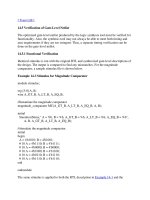
+A and –A method. The AND function can be represented three ways, as shown in
Figure 1.1, using an AND gate, a NAND gate, and a NOR gate. Although only two
inputs are shown, both AND and OR circuits can have three or more inputs. The
plus (+) and minus (–) symbols that are placed to the left of the variables indicate a
high or low voltage level, respectively. This indicates the asserted (or active) voltage
4
Chapter 1
Introduction
level for the variables; that is, the logical 1 (or true) state, in contrast to the logical 0
(or false) state.
Table 1.1 Assertion Levels
Active high assertion +A
Active low assertion –A
A
¬A
A(H)
A(L)
A
*A
A
A
A
A'
Thus, a signal can be asserted either plus or minus, depending upon the active
condition of the signal at that point. For example, Figure 1.1(a) specifies that the
AND function will be realized when both input A and input B are at their more positive potential, thus generating an output at its more positive potential. The word positive as used here does not necessarily mean a positive voltage level, but merely the
more positive of two voltage levels. Therefore, the output of the AND gate of Figure
1.1(a) can be written as + (A & B).
To illustrate that a plus level does not necessarily mean a positive voltage level,
consider two logic families: transistor-transistor logic (TTL) and emitter-coupled
logic (ECL). The TTL family uses a + 5 volt power supply. A plus level is approximately + 3.5 volts and above; a minus level is approximately + 0.2 volts. The ECL
family uses a – 5.2 volt power supply. A plus level is approximately – 0.95 volts; a
minus level is approximately – 1.7 volts. Although – 0.95 volts is a negative voltage,
it is the more positive of the two ECL voltages.
The logic symbol of Figure 1.1(b) is a NAND gate in which inputs A and B must
both be at their more positive potential for the output to be at its more negative
potential. A small circle (or wedge symbol for IEEE std 91-1984 logic functions) at
the input or output of a logic gate indicates a more negative potential. The output of
the NAND gate can be written as – (A & B).
Figure 1.1(c) illustrates a NOR gate used for the AND function. In this case,
inputs A and B must be active (or asserted) at their more negative potential in order
for the output to be at its more positive potential. The output can be written as + (A &
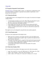
B). A variable can be active (or asserted) at a high and a low level at the same time,
as shown in Figure 1.2.
Figure 1.1(d) shows a NAND gate used for the OR function. Either input A or B
(or both) must be at its more negative potential to assert the output at its more positive potential. The output can be written as + (A | B), where the symbol ( | ) indicates
the OR operation in Verilog.
1.3
Assertion Levels
5
+A
+A
+B
+(A & B)
+B
(a)
+(A & B)
+A
+A
+B
–(A & B)
(b)
+B
–(A & B)
–A
–A
–B
+(A & B)
–B
+(A & B)
(c)
–A
–A
–B
–B
+(A | B)
(d)
+(A | B)
Figure 1.1
Logic symbols and waveforms for AND, NAND, NOR, and NAND
(negative-input OR).
y1
D
+y1
>
–y1
+x1
+x1
Figure 1.2
–x1
Signals can be active high and low at the same time.