2014 Subaru of America
Bạn đang xem bản rút gọn của tài liệu. Xem và tải ngay bản đầy đủ của tài liệu tại đây (11.78 MB, 185 trang )
Technician
Reference
Booklet
2015 Legacy
and Outback
New Technology Training
Module 926
MSA5P1926C
June 2014
This Technical Reference Booklet (TRB) is designed to be used in a
classroom environment or as a guide for self study.
The TRB is not intended to be used as a supplement or substitute for
the Subaru Service Manual. Always consult the appropriate Service
Manual when performing any diagnostics, maintenance or repair to any
Subaru vehicle.
© Copyright 2014
Subaru of America, Inc.
All rights reserved. This book may not be
reproduced in whole or in part without the
express permission of Subaru of America,
Inc. Specifications in this Guide are based
on the latest product information available at
the time of publication. Some images shown
are for illustration purposes only.
Subaru of America, Inc. reserves the right at
any time to make changes or modifications
to systems, procedures, descriptions, and
illustrations contained in this book without
necessarily updating this document.
Information contained herein is considered
current as of June 2014.
© 2014 Subaru of America, Inc. Printed in USA. All rights reserved. Contents may not be reproduced in whole or in part without
prior written permission of publisher. Specifications in this Guide are based on the latest product information available at the
time of publication. Some images shown are for illustration purposes only. Some equipment shown in photography within this
Guide is optional at extra cost. Specific options may be available only in combination with other options. Specific combinations of
equipment or features may vary from time to time, and by geographic area. Subaru of America, Inc. reserves the right to change
or discontinue at any time, without notice: Prices, colors, materials, equipment, accessories, specifications, models and packages,
without incurring any obligation to make the same or similar changes on vehicles previously sold. Colors shown may vary due to
reproduction and printing processes. Subaru of America, Inc. is not responsible for typographical errors. Aha™ is a trademark
of HARMAN International Industries, Inc.) Alcantara® is a registered trademark of Alcantara S.p.A., and Alcantara is produced
by the Toray Group. BBS® is a registered trademark of BBS Kraftahrzeugtechnik AG. Bluetooth® is a registered trademark of
Bluetooth SIG, Inc. Brembo® is a registered trademark of Freni Brembo S.p.A. CS Auto, Circle Surround Automotive and WOW
are trademarks of SRS Labs, Inc. Ecsaine® is a registered trademark of Toray Industries, Inc. Harman Kardon® is a registered
trademark of Harman International Industries, Inc. HD Radio® is a registered trademark of iBiquity Digital Corporation. HomeLink®
is a registered trademark of Prince Corporation, a wholly owned subsidiary of Johnson Controls. iPod® is a registered trademark of
Apple Inc. iTunes® is a registered trademark of Apple Inc. Metal-Matrix Diaphragm (MMD®) is a registered trademark of Harman
International Industries, Inc. Smart Way is a registered trademark of the U.S. Environmental Protection Agency. SRS(●)® Circle
Surround Automotive and WOW are registered trademarks of SRS Labs, Inc. TORSEN LSD® is a registered trademark of JTEKT
TORSEN North America, Inc. SiriusXM® is a registered trademark of SiriusXM Satellite Radio, Inc. / SiriusXM NavTraffic® is a
registered trademark of SiriusXM Satellite Radio, Inc. Added Security, BRZ, EyeSight, Impreza, Forester, Lineartronic, Legacy,
Outback, Subaru, SUBARU BOXER, Tribeca, and WRX, STI, and XV Crosstrek are registered trademarks of Fuji Heavy Industries,
Ltd. Subaru STARLINK is a trademark of Fuji Heavy Industries, Ltd.
© Subaru of America, Inc. 2014
926 R-1
2015 Legacy and Outback
New Technology Training
Table of Contents
(Module 926)
Introduction............................................................................................................................... 8
Body................................................................................................................................. 8
Active Grille Air Shutter System (AGAS)............................................................... 9
Bumper Cover Removal.......................................................................................11
Radiator or Condenser Removal......................................................................... 13
Fuel Tank Position Check.................................................................................... 15
Battery Hold Down Bracket................................................................................. 16
Tool Kit and Spare Tire........................................................................................ 17
Coolant Fan Mounting......................................................................................... 18
HVAC.................................................................................................................. 19
Rear Vent Door Actuator Operation..................................................................... 20
Sun Visors........................................................................................................... 21
Audio and Navigation.......................................................................................... 21
6.2 Inch Display.................................................................................................. 22
7.0 Inch Display................................................................................................... 23
Rear Window Regulator...................................................................................... 24
Trailer Adapter Connector................................................................................... 25
Assist Grip Removal............................................................................................ 26
Dash Pad............................................................................................................ 28
Steering Support Beam and Wiring Harnesses.................................................. 30
Electrical.................................................................................................................................. 34
Introduction..................................................................................................................... 34
Battery............................................................................................................................ 34
Battery Sensor.................................................................................................... 34
Wiring & Connectors....................................................................................................... 35
Fuse Box............................................................................................................. 35
Lighting........................................................................................................................... 36
Welcome Lighting............................................................................................... 37
Day-time Running Lamps (DRL)......................................................................... 39
Steering-Responsive Fog Lights (SRF).............................................................. 40
Immobilizer & Keyless Entry............................................................................... 47
Combination Meter.............................................................................................. 48
LAN/CAN Changes........................................................................................................ 50
CAN Diagnostics................................................................................................. 51
BIU................................................................................................................................. 54
4
June 2014
2015 Legacy and Outback
New Technology Training
(Module 926)
Power Rear Gate (PRG).......................................................................................................... 56
Construction................................................................................................................... 58
Electrical Control............................................................................................................ 60
Touch Sensors................................................................................................................ 62
Separating the Rear Gate from the PRG Assembly....................................................... 66
Rear Gate will not close...................................................................................... 66
Rear Gate will not open...................................................................................... 67
“Memory Height” Learning Procedure............................................................................ 68
Retrieval of the rear gate height:......................................................................... 69
Operating Characteristics................................................................................... 69
Rear gate drop prevention function..................................................................... 69
Supplemental Restraint System (SRS)................................................................................. 72
Airbag components............................................................................................. 73
The Front Seat Side Airbags................................................................................74
Seat Cushion Airbag........................................................................................... 75
Curtain Airbag..................................................................................................... 78
Occupant Detection System................................................................................ 82
Front Passenger Seat Construction.................................................................... 83
Deployment Logic............................................................................................... 84
Additional Information .................................................................................................... 86
Chassis.................................................................................................................................... 88
Introduction..................................................................................................................... 88
Front Suspension Key Changes include:............................................................ 88
Front Stabilizer Link............................................................................................ 88
Control Arm Bushings Rear................................................................................ 89
Rear Suspension................................................................................................ 90
Alignment............................................................................................................ 90
Dampers (Front and Rear).................................................................................. 91
Active Torque Vectoring....................................................................................... 91
Tire Pressure Monitoring Systems...................................................................... 93
EyeSight® (Version 3)............................................................................................................ 94
Introduction..................................................................................................................... 94
System Features............................................................................................................. 96
Adaptive Cruise Control...................................................................................... 96
Pre-collision Braking Control............................................................................... 97
Pre-collision Steering Assist (NEW).................................................................... 98
Pre-collision Braking Assistance......................................................................... 99
Pre-collision Throttle Management...................................................................... 99
Lane Departure Warning..................................................................................... 99
Lane Sway Warning............................................................................................ 99
System Layout...............................................................................................................100
Camera Adjustment.......................................................................................................102
Point A................................................................................................................103
Point B................................................................................................................104
5
June 2014
2015 Legacy and Outback
New Technology Training
(Module 926)
Subaru Rear Vehicle Detection (SRVD)................................................................................106
Introduction....................................................................................................................106
Subaru Rear Vehicle Detection functions......................................................................106
Blind Spot Detection (BSD)................................................................................106
Lane Change Assist (LCA).................................................................................106
Rear Cross Traffic Alert (RCTA)..........................................................................107
Operating Conditions.........................................................................................107
Driver Alerts...................................................................................................................108
SRVD Approach indicator lights.........................................................................108
Rear View Camera Indicator..............................................................................109
SRVD Approach Warning Buzzer....................................................................... 110
Construction.......................................................................................................112
SRVD “OFF” Switch...........................................................................................115
Diagnostics........................................................................................................116
Radar Axis Alignment.........................................................................................118
SSM Procedure................................................................................................. 123
Brakes.................................................................................................................................... 126
EPB Construction and Operation...................................................................... 129
EPB Electrical Operation and Control.......................................................................... 132
New EPB Features....................................................................................................... 136
Emergency Brake Operation........................................................................................ 137
Emergency Release of the EPB........................................................................ 137
Servicing Rear Brake Pads............................................................................... 139
Electric Power Steering (EPS)............................................................................................. 142
Introduction................................................................................................................... 142
Major Changes............................................................................................................. 142
Electric Power Steering Circuit..................................................................................... 143
Drive Motor....................................................................................................... 144
Resolver Sensor................................................................................................ 145
Torque Sensor................................................................................................... 146
Magnetic Ring................................................................................................... 146
Flux Rings......................................................................................................... 147
Flux Collecting Rings........................................................................................ 147
Flux Collecting Yoke.......................................................................................... 148
Flux Collecting Yoke.......................................................................................... 149
Alignment Collar................................................................................................ 150
Diagnostics....................................................................................................... 151
6
June 2014
2015 Legacy and Outback
New Technology Training
(Module 926)
Powertrain............................................................................................................................. 154
FB 2.5........................................................................................................................... 154
Piston................................................................................................................ 154
Intake Cam Sprockets....................................................................................... 155
Exhaust Cam Sprockets.................................................................................... 155
Exhaust Cam Sprocket SST.............................................................................. 156
Valve Adjustment............................................................................................... 156
Cylinder Head................................................................................................... 156
Intake Manifold & Tumble Generating Valves (TGV)......................................... 157
Exhaust Manifold.............................................................................................. 158
Exhaust Gasket................................................................................................. 158
Fuel Pipe........................................................................................................... 159
Ignition Coil....................................................................................................... 160
EGR Cooler....................................................................................................... 160
Evaporative Emissions...................................................................................... 161
EZ 3.6 Changes........................................................................................................... 164
SST Check Boards............................................................................................ 167
Engine Removal........................................................................................................... 168
Engine Removal................................................................................................ 168
Lineartronic Continuously Variable Transmission Generation 2 (CVT G2/TR58)..........174
Introduction........................................................................................................174
Shifting Control...................................................................................................174
CVT Fluid.......................................................................................................... 175
Internal changes............................................................................................... 175
CVT Vent............................................................................................................176
CVT Cooler........................................................................................................176
Dynamic Damper.............................................................................................. 177
Transfer Clutch Pressure Test........................................................................... 177
Transmission Control Module (TCM)................................................................. 178
Lineartronic Continuously Variable Transmission High-torque Generation 1 (CVT G1/
TR69)........................................................................................................................... 179
Introduction....................................................................................................... 179
Forward & Reverse Changeover mechanism.................................................... 180
Vent................................................................................................................... 181
TCM.................................................................................................................. 181
Shifter................................................................................................................ 182
Shift Lock Release............................................................................................ 183
7
June 2014
2015 Legacy and Outback
Introduction
New Technology Training
(Module 926)
Body
The 2015 model year of the Legacy and Outback introduces full model changes that focus on
safety, fuel efficiency, and improved Human Machine Interface Systems.
1-1
1-2
2015 Legacy
2015 Outback
Legacy Model Lineup
2.5i
2.5i Premium
2.5i Limited
3.6R Limited
Outback Model Lineup
2.5i
2.5i Premium
2.5i Limited
3.6R Limited
All models are equipped with Lineartronic Continuously Variable Transmissions (CVT). Generation
2 CVT (TR58) will be installed on 2.5i vehicles. High torque Generation 1 CVT (TR69) will be
installed on all 3.6R models.
New or enhanced driver assistance systems:
- Welcome Lighting
- Steering Responsive Fog lights
- Electronic Power Steering
-Eyesight
- Subaru Rear Vehicle Detection
- X Mode
New or enhanced safety systems:
- Supplemental Restraint System Airbags
- Electronic Parking Brake
8
June 2014
2015 Legacy and Outback
New Technology Training
(Module 926)
The Legacy and Outback for 2015 are approximately 10% more aerodynamic. This streamlining is
the result of design changes to the front and rear corners of the vehicle, side view mirrors, under
chassis air flow, and introduction of the Active Grille Air Shutter System (AGAS).
Active Grille Air Shutter System (AGAS)
All 4 cylinder models of the 2015 Legacy and Outback are equipped with the Active Grille Air
Shutter System (AGAS).
The AGAS is designed to improve fuel efficiency by improving body aerodynamics and decreasing
engine warm up time.
1-3
1-4
AGAS Closed
AGAS Open
The AGAS defaults to the open position in case of electrical communication malfunction.
Note: The AGAS is not spring loaded to the open position.
Note: The AGAS will remain closed if the ambient temperature is lower than 37 degrees
Fahrenheit (3 degrees C).
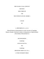
The opening and closing of the AGAS is determined by ambient temperature, coolant temperature,
and vehicle speed.
The three wire actuator receives command signals and transmits its position through a single LIN
communications wire that is routed to the Engine ECM.
9
June 2014
2015 Legacy and Outback
New Technology Training
(Module 926)
1-5
AGAS Actuator
Note: The Engine ECM of the 2015 Legacy and Outback is LIN compatible.
During service or replacement, the AGAS automatically initializes so there is no special procedure
required to calibrate the AGAS to the vehicle.
Note: Work support for the AGAS has been added to the ECM menu.
R/B
MB-2
M/B FUSE NO. 30
(B)
ACTIVE GRILLE
SHUTTER
2
R/B
3
W
4
B
ECM
A55
A : B 134
B
W
5
B63
B491
J/C
REF. TO GND [m]
1-6
AGAS Wiring Schematic
10
June 2014
2015 Legacy and Outback
New Technology Training
(Module 926)
Bumper Cover Removal
Bumper cover removal is necessary when removing the radiator. The bumper cover (front and
rear) is attached to the body with trim clips only.
Begin bumper cover removal by removing the six clips along the top side at the indicated positions.
1-7
Upper Clips
1-8
Inner Fender Clip
Elevate the vehicle and remove the inner fender trim tab from each front inner wheel well. Raise
the vehicle high enough to remove the three lower bumper cover trim tabs and the three trim tabs
located in front of each tire.
1-9
Lower Clips
11
June 2014
2015 Legacy and Outback
New Technology Training
(Module 926)
Lower the access panel and disconnect the fog light connector (left and right).
Pull outward and upward to disengage the bumper cover locking tabs from the body mounts.
1-10
1-11
Fog Light
Removing Bumper Cover
Place the bumper cover in a safe location. Inspect the locking tabs and body mounts for damage.
1-12
1-13
Front End
Locking Tabs
Note: The bumper cover locking tabs have been strengthened to prevent deformation
during removal.
1-14
DRL Resistor
The Daytime running light resistor, horn, and windshield washer reservoir are located under the
leftside of the bumper cover. The second horn is located under the right side of the bumper cover.
12
June 2014
2015 Legacy and Outback
New Technology Training
(Module 926)
Radiator or Condenser Removal
Note: Radiator or condenser removal requires bumper cover removal.
After bumper cover removal, remove the four clips along the top and the two clips that face forward
that secure the grille bracket to the vehicle and remove the grille bracket.
1-15
1-16
Grille Bracket Clips
Under Grille Bracket
Remove the left and right upper radiator brackets, and two upper radiator to condenser bolts.
1-17
1-18
Upper Radiator Bracket
Condenser To Radiator Bracket
Next remove the bolts that secure the “condenser to radiator bracket”.
13
June 2014
2015 Legacy and Outback
New Technology Training
(Module 926)
Remove the left and right lower bolts first, then the 4 upper bolts. Remove the two brackets from
the vehicle to prevent damage to the radiator or condenser.
Note: For lower bolt removal:
The radiator and condenser can be raised slightly as an assembly for bolt
removal while using a socket and ratchet. The SST 73099SG000 must be used to
correctly torque the bolt(s). The radiator and condenser must be seated before
the bolt(s) are torqued.
1-19
1-20
Removing Lower Bolt
Upper Bolts
Secure the condenser to the vehicle with string to prevent damage as the radiator is removed.
1-21
Condenser Secured
If the condenser is being removed, leave the radiator in the vehicle with the coolant hoses attached.
Push the radiator inward slightly and remove the condenser.
14
June 2014
2015 Legacy and Outback
New Technology Training
(Module 926)
Fuel Tank Position Check
A new positioning check is required if the fuel tank is removed from the vehicle. A new fuel tank
positioning mark is made onto the vehicle.
1-22
1-23
Fuel Tank
Measuring Fuel Tank Position
Check that the leading edge of the fuel tank is 14.5 millimeters or less as measured in the picture
above. Reposition the fuel tank if the measurement exceeds the specification. Measurements
exceeding specifications that cannot be adjusted to specifications, indicate damage has occurred
to the tank or the vehicle body.
NOTES:
15
June 2014
2015 Legacy and Outback
New Technology Training
(Module 926)
Battery Hold Down Bracket
A new battery hold down bracket with captured mounting bolts and positioning guide is installed
on the new Legacy and Outback.
1-24
1-25
Battery Hold Down Bracket Bolt and Guide
Guide in Place
The positioning guide temporarily holds the new bracket in place while the bolts are started.
Note: The mounting bolt capture washer may stay with the battery tray upon removal.
Retain the washer for bolt installation.
1-26
1-27
Hold Down Bracket Complete
Battery Tray
The battery hold down positioning guide is installed on the inboard side of the battery (engine side).
16
June 2014
2015 Legacy and Outback
New Technology Training
(Module 926)
Tool Kit and Spare Tire
The tool kit of the Outback includes a tow hook and a flat tire storage bag with tie down strap.
The storage bag is needed because the spare tire well is not large enough to hold a flat full size
tire (225/60 R18).
Note: The Legacy tool kit does not include a tow hook.
1-28
1-29
Tool Kit
Flat Tire Bag and Tie Down Strap
The Outback spare tire is a T155/80 R 17. A polystyrene spacer prevents the spare tire from creating
any noise or vibration while stored.
1-30
1-31
Spare Tire
Spacer
An air bubble filled painted vibration dampening sheet coats the bottom of the spare tire well.
17
June 2014
2015 Legacy and Outback
New Technology Training
(Module 926)
Coolant Fan Mounting
The coolant fan assembly is attached to the radiator and can be removed with the radiator still
mounted in the vehicle.
Note: Engine coolant must be drained to allow the coolant overflow bottle and the
upper radiator hose to be removed.
1-32
1-33
Radiator and Cooling Fans
Upper Locking Tab
The upper left and right corners of the coolant fan assembly are secured to the radiator with locking
tabs that are disengaged by squeezing the two tabs together.
1-34
1-35
Removing Cooling Fans
Lower Docking Slot
The two lower corners are positioned into a docking slot and do not require any unlocking for
removal. Lift the coolant fan assembly away from the radiator after the two upper locking tabs
have been released.
18
June 2014
2015 Legacy and Outback
New Technology Training
(Module 926)
HVAC
The Legacy and Outback 2.5i models are equipped with Manual Air Conditioning. 2.5i Premium
and Limited Models are equipped with Dual Zone Automatic Climate Control.
2.5i Premium and Limited Models are also equipped with rear seat air conditioning vents and
rear seat heaters.
Note: The temperature output to the rear seat air conditioning vents is controlled by
the temperature setting for the passenger side front.
1-36
1-37
HVAC Controls
Rear A/C Vents and Seat Heater Switches
1-38
Rear Seat Heater Control Unit
The 2 level rear seat heaters are controlled by the Rear Seat Heater Control Unit, which is
located in the left rear of the vehicle.
Note: The front seat heaters retain their set positions after the ignition has been
turned off. The rear seat heaters default to off.
19
June 2014
2015 Legacy and Outback
New Technology Training
(Module 926)
Rear Vent Door Actuator Operation
The rear vent door actuator (introduced 2013 MY) controls the temperature of the air delivered to
the rear passengers through the center console rear vents. Set temperature for the rear passengers
is strictly controlled by the front passenger temperature control dial. Airflow mode setting has no
effect on rear vent door actuator position. The rear vent door actuator mixes chilled air from the
evaporator with heated air from the heater core. The SSMIII PID for this is Rr Vent Door Actuator
Position.
If the displayed value is at 75% (lowest temperature setting), the rear vent door is biased to
allow more cold air to flow. As the PID value decreases from 75% to -5% (temperature set point
increased) the amount of cold air mixed decreases and hot air increases. At the lowest value of
-5% (highest temperature setting) the air flow will essentially shut off for both hot and cold. Work
Each System Check
support can be accessed on the SSMIII by selecting All other models
Air Condition System
Work Support
System Operation Check Mode.
(5)
(1)
(2)
(3)
(4)
(5)
(6)
(7)
(8)
(6)
(8)
(1)
(2)
(7)
Duct-rear heater LH
Duct-rear heater RH
Duct-extension LH
Duct-extension RH
Duct-console front
Duct-console rear
Center console duct
Grille ASSY-rear heater
(3)
1-39
(4)
HVAC Duct Layout
The actuator can only be replaced by removing the heating and cooling unit and blower motor
housing from the vehicle.
1-40
1-41
Rear A/C Vent Actuator
In Compartment HVAC Assembly
20
June 2014
2015 Legacy and Outback
New Technology Training
(Module 926)
Sun Visors
The Sun Visors are mounted on a sliding rod that allows the position of the Sun Visor to be adjusted
after being moved to the side.
1-42
1-43
Sun Visor Collapsed
Sun Visor Expanded
Audio and Navigation
The 2015 Legacy and Outback will be equipped with 3 styles of Audio and Audio/Navigation systems.
1-44
1-45
6.2 Inch Display
7 Inch Display
1-46
7 Inch Display With Navigation
The 2.5i models will be equipped with the Clarion Audio Infotainment system with a 6.2 inch display.
2.5i Premium and Limited models will be equipped with the Fujitsu Ten Audio Infotainment system
with a 7.0 inch display. An optional Fujitsu Ten Audio and Navigation Infotainment system with a
7.0 inch display, will be available for the 2.5i Premium and Limited models.
The 7.0 inch display Infotainment systems have voice control capability and can communicate with
the Automatic Climate Control, via UART, allowing the HVAC to be operated with voice commands.
Note: Refer to the Subaru owner’s manual for a list of voice commands.
The 7.0 inch display Infotainment systems are connected to the high speed Body CAN. This allows
communication between the Fujitsu Ten and the Subaru Select Monitor.
21
June 2014
2015 Legacy and Outback
New Technology Training
(Module 926)
Diagnostic Trouble Codes are also available to assist with diagnostics. The data displayed provides
more detailed data than the built in Line Check function.
Both the 6.2 inch and 7.0 inch Infotainment systems are equipped with Line Check functions.
6.2 Inch Display
1. (a) Press the button to display the Audio OFF screen.
2. Touch the screen in order from (b) to (e).
(a)
(b)
(c)
(d)
(e)
1-47
Activating Line Check
Note: To exit the diagnostic mode, turn the ignition switch from ACC OFF to ON.
3. <<LineDiag>> screen is displayed.
Line Diag
Connectivity Check
MIC
Rr_CAM
USB
AUX
SXM
UART
Vehicle Signal Check
ILL +
OK
OK
OK
OK
OK
OK
Camera Setting
SPD
PKB
REV
OFF
OFF
ON
OFF
Audio Check
1-48
Line Diagnostic Information
This Line Check function allows the displayed signals to be checked for connection to the
Infotainment system. Activate each device to create the input signal needed to change the detection
status from NG to OK.
The Camera Setting allows adjustment of the displayed guide lines that appear when the vehicle
is in reverse gear range. Audio check rotates the sound from the radio to each speaker. Turn up
the volume to monitor each speaker.
22
June 2014
2015 Legacy and Outback
New Technology Training
(Module 926)
7.0 Inch Display
1. With the main power OFF, press the button (b) twice while pressing the button (a)
simultaneously.
(b)
(c)
(a)
1-49
Activating Line Check
Note: Pressing the button (c) for 3 seconds or more, or turning the ignition from ACC OFF
to ON position can exit the diagnostic mode.
2. << Line Diag>> screen is displayed.
3. Check the connection status for each item listed in {Connectivity Check} displayed on
the left of the screen.
This Line Check function allows the displayed signals to be checked for connection to the
Infotainment system. Activate each device to create the input signal needed to change the detection
status from NG to OK.
The Camera Setting allows adjustment of the displayed guide lines that appear when the vehicle
is in reverse gear range. Audio check rotates the sound from the radio to each speaker. Turn up
the volume to monitor each speaker.
Note: GPS will indicate NG on non-Navigation equipped Infotainment systems.
Line Diag
Connectivity Check
GPS
MIC
Rr_CAM
AUX
USB1
USB2
OK
OK
OK
OK
OK
OK
Camera Setting
Vehicle Signal Check
UART
CAN
OK
OK
OK
ILL +
SPD
PKB
REV
IGN
OFF
OFF
ON
OFF
OFF
Audio Check
1-50
Line Diagnostic Information
Note: The vehicle signal check does not change to “OFF” after a signal has been
received (ON) and then removed, until the ignition is cycled.
23
June 2014
2015 Legacy and Outback
New Technology Training
(Module 926)
Rear Window Regulator
The rear window regulator of the Legacy and Outback is described as an “I Arm” window regulator.
This type uses a single roller that moves through a channel that is attached to the window glass.
The height of the window is controlled by the position of the roller in the channel.
1-51
1-52
Rear Window Assembly
I Arm And Roller
The regulator is attached to the door with 4 bolts and is easily removed through the opening in
the lower section of the door.
1-53
1-54
Regulator Mounting Points
Window Taped In Position
The window glass must be taped to the door to prevent the glass from dropping after the regulator
has been removed.
24
June 2014
2015 Legacy and Outback
New Technology Training
(Module 926)
1-55
Back Side Of Regulator
Trailer Adapter Connector
The trailer adapter connector is taped to the body behind the trim panel on the left rear of the
vehicle, just behind the rear seat.
1-56
Trailer Adapter Connector
25
June 2014