Module 7 TPMS (tire pressure monitoring system) eng
Bạn đang xem bản rút gọn của tài liệu. Xem và tải ngay bản đầy đủ của tài liệu tại đây (1.25 MB, 26 trang )
Textbook
Module7 TPMS (Tire Pressure Monitoring System)
Module7 TPMS (Tire Pressure
Monitoring System)
7.1
O
nl
y
LESSON
Overview ...........................................................................................................................177
7.1.1 Introduction..................................................................................................................... 177
7.1.2 Comparison between US and EU Regulation ................................................................ 178
7.1.3 High Line and Low Line.................................................................................................. 179
Components .....................................................................................................................181
7.3
Main Components .......................................................................................................... 181
Tire Pressure Sensor (WE Sensor) ................................................................................ 182
Receiver ......................................................................................................................... 183
Warning Lamp and Position Lamp ................................................................................. 184
se
7.2.1
7.2.2
7.2.3
7.2.4
lU
7.2
Control ..............................................................................................................................187
na
7.3.1 Operation Flow Chart and System Block ....................................................................... 187
7.3.2 Primary Function (High Line TPMS for North America) ................................................. 188
7.3.3 Auto Location Logic........................................................................................................ 191
Sensor Mounting ............................................................................................................ 195
Notes on Tire Handling................................................................................................... 197
Replacement Procedure................................................................................................. 198
TPMS Exciter ................................................................................................................. 200
Ed
7.4.1
7.4.2
7.4.3
7.4.4
tio
TPMS Maintenance ..........................................................................................................195
uc
a
7.4
[Learning Objective]
Fo
r
▪ Explain the difference between the low line and high line of TPMS.
▪ Describe the system layout and list the locations, mechanisms and functions of components.
▪ Describe the mechanism of the main functions.
▪ Take necessary actions after a part change and list the cautionary measures required for
maintenance.
Basic Chassis Technology
175
Textbook
Fo
r
Ed
uc
a
tio
na
lU
se
O
nl
y
Module7 TPMS (Tire Pressure Monitoring System)
176
Basic Chassis Technology
Textbook
Module7 TPMS (Tire Pressure Monitoring System)
Overview
7.1.1
Introduction
O
nl
y
7.1
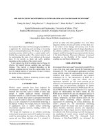
Figure 7-1 Insufficient Tire Pressure (left) / Alarm on Cluster (right)
lU
se
TPMS stands for Tire Pressure Monitoring System, which was first applied to vehicles exported to North
America in accordance with the NHTSA FMVSS 138, and later the application extended to export vehicles
bound for Europe.
na
TPMS has been applied on the vehicle as an advanced safety device since the related regulation.
According to the frequent accident due to the insufficient tire pressure, it has been necessary to develop
more reliable system to monitor the actual pressure and give a proper telltale to the driver while driving.
tio
VG F/L has been equipped with a tire pressure monitoring system (TPMS) that illuminates a low tire
pressure telltale when one or more of your tires is significantly under-inflated through warning lamp on
cluster. Accordingly, when the low tire pressure telltale illuminates, you should stop and check your tires
as soon as possible, and inflate tires.
uc
a
Driving on a significantly under-inflated tire causes the tire to overheat and can lead to tire failure.
Under-inflation also reduces fuel efficiency and tire tread life, and may affect the vehicle’s handling and
stopping ability.
Ed
Please note that the TPMS is not a substitute for proper tire maintenance, and it is the driver’s responsibility
to maintain correct tire pressure, even if under-inflation has not reached the level to trigger illumination of
the TPMS low tire pressure telltale.
Fo
r
TPMS unit can detect system failure by itself. Under abnormal condition, cluster lamp blinks for 1min then
on.
When this happen, the system may not be able to detect or signal low tire pressure as intended.
Basic Chassis Technology
177
Module7 TPMS (Tire Pressure Monitoring System)
Comparison between US and EU
Regulation
O
nl
y
7.1.2
Textbook
lU
se
Basically, “when warning lamp turns on” is related to the regulation in their region. Therefore, before we
learn about TPMS basic function, we should understand the regulation. In EU / US region, they have
different alarm set level since their regulation are not same.
‘If the temperature get higher, pressure also get higher.’ This is the basic theory in nature. In EU region,
they reflect this theory into their regulation. Therefore, their alarm set level increase, if the tire get warmer.
tio
na
You can check their alarm set level through lower figures. PEU means RCP considering temperature
compensation logic. And PUS means just RCP which is independent value from temperature. FYI, RCP
means Recommended Cold Pressure. (Standard tire pressure in cold state)
In EU region, alarm set level is “below 20% from PEU” and it is altered with tire temperature.
Fo
r
Ed
uc
a
But US region, they have independent value from temperature which is “below 25% from RCP (PUS).”
178
Basic Chassis Technology
Textbook
7.1.3
Module7 TPMS (Tire Pressure Monitoring System)
High Line and Low Line
lU
se
O
nl
y
TPMS is mainly categorized as the High-Line and Low-Line. The difference between the two types is
whether the tire position malfunction lamp turns on or not. The High-Line type can indicate to the driver
which tire is low in pressure using the tire position malfunction lamp. With the Low-Line type, the system
indicates that a low pressure has been detected, but the driver does not know which tire it is. In order to
find which tire has low pressure, High Line system needs auto location function.
High Line
WE Sensor (4EA)
tio
Zero Initiator (deleted)
na
Receiver (1EA)
Low Line
Receiver (1EA)
WE Sensor (4EA)
Zero Initiator
No indicator for the low pressure tire
Tire rotation: Auto. teaching for Sensor ID
Tire rotation : Manual teaching for Sensor ID
Fo
r
Ed
uc
a
Indicator for the low pressure tire
Basic Chassis Technology
179
Textbook
Fo
r
Ed
uc
a
tio
na
lU
se
O
nl
y
Module7 TPMS (Tire Pressure Monitoring System)
180
Basic Chassis Technology
Textbook
Module7 TPMS (Tire Pressure Monitoring System)
Components
7.2.1
Main Components
Fo
r
Ed
uc
a
tio
na
lU
se
O
nl
y
7.2
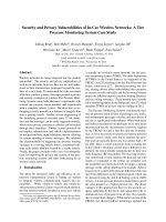
Figure 7-2 System Layout
Tire Pressure Sensor measures the pressure and temperature of the tires and it sends these data to the
Receiver via radio frequency. At the same time, the receiver retrieves the vehicle speed from the EMS and
the wheel pulse from the ESC (ABS) via CAN communication to determine the location of the tires.
If a tire reports a problem, that tire is immediately identified and appears in a warning lamp on the cluster.
The method to identify tires is discussed later in the Auto-Location section.
Basic Chassis Technology
181
Module7 TPMS (Tire Pressure Monitoring System)
7.2.2
Textbook
Tire Pressure Sensor (WE Sensor)
O
nl
y
1) Exploded View of Wheel Sensor and Its Role
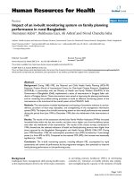
Figure 7-3 Location (left) / WE Sensor (right)
tio
na
lU
se
The tire pressure sensor is called ‘WE sensor’. (WE: Wheel Electronic) The tire pressure sensor weighs
about 35 g, and is fitted to the rim of each wheel (4 in total), except to that of the spare tire. A small cell
battery is embedded in the sensor. Its battery life is about 10 years. The pressure sensor measures the
tire pressure, temperature, acceleration, the battery voltage, etc., and sends the data with the sensor ID
to the TPMS receiver via RF. The measurement frequency and transmission frequency are set differently
to extend the battery life in the sensor. Each sensor has a unique ID number, so if the sensor is replaced
or the tire position has changed, a new ID must to be registered in the Receiver . The tire pressure
sensor component cannot be checked for faults with a conventional multimeter or wave forms because it
is wireless, so a separate wireless diagnostic tool (TMPS exciter) is used to communicate with the sensor
to read its ID or check the data measured by the sensor. It uses RF (Radio Frequency) signal to transmit
to the TPMS receiver, and the emitted frequency is 433 MHz in Euro and General market.
Mode
uc
a
2) Mode for Tire Pressure Sensor
Ed
MP (Parking Mode)
Fo
r
MFB (First Block Mode)
MD (Driving Mode)
MI (Interim Mode)
Description
Freq.
▪ Keeping no motion status for 15 min.
13 Hours
▪ Mode for parking and A/S part.
▪ In MP, if sensor notice a change over 4g, MFB is activated.
16 sec
▪ This mode is kept only for about 10min.
▪ Mode for Auto Learning / Location.
In MFB Mode, it keeps moving condition (>4g) for 10min,
enter into MD mode.
▪ In MD or MFB, if it notice no motion (<3g), enter into MI
immediately.
64 sec
None
▪ Mode for preparing
182
Basic Chassis Technology
Textbook
Module7 TPMS (Tire Pressure Monitoring System)
7.2.3
Receiver
O
nl
y
1) Exploded View of Receiver and Its Role
Figure 7-4 Mounting Location: Cowl Crossbar inside the Crash Pad
se
Receiver receives RF signals (315MHz) from the tire pressure sensors and then analyzes data. it also
receives vehicle speed signal and wheel pulse signal from EMS, ESC(ABS) at the same time.
lU
The reason Receiver get the signal from EMS, ESC(ABS) is for preforming Auto Learning and Auto
Location. And it controls Warning lamp on cluster.
2) Receiver Mode
Mode
System
Test Mode
Normal
Virgin Mode
Not operated
TPMS W/L
Blinking
Normal Mode
Normal
-
na
Lamp Status
▪ TPMS operation test
▪ Mode for factory Line
▪ A Sensor ID is not registered
▪ Mode for A/S part
▪ Registered sensor ID
▪ Normal operating status
TIP
Ed
uc
a
tio
TPMS W/L ON
Remark
Fo
r
Depending on the manufacturer, three or four initiators are installed on a single high-line TPMS for
sensor location detection. Manufacturers are opting to not install initiators as sensor locations can
be detected using pressure sensor signal intensity and the acceleration sensor inside the sensors,
as well as for cost-reduction reasons.
Initiators perform the following functions when installed.
▪ Emits LF signal to the sensor
▪ Wake-Up the sensor
▪ Tire position detection
Basic Chassis Technology
183
Module7 TPMS (Tire Pressure Monitoring System)
7.2.4
Textbook
Warning Lamp and Position Lamp
1) Warning Lamp for Low Pressure
Normal Operation
Wrong Operation
Normal Mode (Start
up check mode)
TPMS doesn’t learned sensor ID (s)
O
nl
y
Virgin Mode (A sensor
ID isn’t stored)
No low pressure tire
Low pressure lamp on operation
Normal operation
Malfunction lamp on operation
lU
Malfunction Lamp
se
Low Pressure Lamp
1 Normal mode
na
When the vehicle is in a normal state, the Warning Lamp is turned on for 3 seconds with ignition ON
and thereafter turned off.
tio
2 Virgin mode
A sensor ID isn’t stored, the warning lamp keeps blinking.
3 Low pressure lamp
Fo
r
Ed
uc
a
When the tire pressure is lower than a specified value, the warning lamp turned on. Usually, it is turned
on when the pressure drops lower than 26 - 27psi. And when the pressure is over 30, 31psi, it is turned
off.
Figure 7-5 Tire Pressure
4 Malfunction lamp
When the system is in failure, the lamp blinks for 60 seconds.
184
Basic Chassis Technology
Textbook
Module7 TPMS (Tire Pressure Monitoring System)
2) Position Lamp
O
nl
y
It is used for High-Line only. It is turned on together with the Warning lamp (Tread lamp) and the cluster
message to show the driver which tire has a pressure lower than the specified value.
Position Lamp
Fo
r
Ed
uc
a
tio
na
lU
se
Warning Lamp
Basic Chassis Technology
185
Textbook
Fo
r
Ed
uc
a
tio
na
lU
se
O
nl
y
Module7 TPMS (Tire Pressure Monitoring System)
186
Basic Chassis Technology
Textbook
Module7 TPMS (Tire Pressure Monitoring System)
Control
7.3.1
Operation Flow Chart and System Block
Fo
r
Ed
uc
a
tio
na
lU
se
O
nl
y
7.3
Basic Chassis Technology
187
Module7 TPMS (Tire Pressure Monitoring System)
7.3.2
Textbook
Primary Function (High Line TPMS for
North America)
Function
Description
Remark
▪ Warn on = RCP × 75% + 7kpa = 172kpa(25psi)
▪ Warn off = RCP - 14kpa = 207kpa(30psi)
* VG F/L RCP: 221kpa(32psi)
▪ Based on ALL Genuine Part(17,18,19 inches)
Tire Fast Leak
Detection
Sensing a rapid air leak over 20kPa/min (3psi/min)
▪ VS over 25kph / 1 RF Frame (Known ID)
▪ VS over 25kph / 8 RF Frame (Unknown ID)
lU
* VS: Vehicle Speed
VS over 25kph
Accumulating information of wheel pulse from ESC/ABS
every 16 sec
na
Auto Locatio
Only Activating in driving
(To avoid activating a
driver deflate a tire on
purpose)
se
Auto Learnin
Margin exists for
hysteresis (+7, -14kpa)
O
nl
y
Under-Inflation
Detection
Failure condition: about
10 min
Failure condition: 40
times (40*16=660sec)
(MAX 40 times, MIN 10 times)
Turning on warning lamp via system diagnosis. DTC
set.
Refer to DTC Sheet.
uc
a
1) Under-inflation Detection
tio
Self-Diagnosi
The most basic function of the TPMS is turning warning lamps on when tire pressure drops. Specific
condition is refer to upper table.
Ed
2) Tire Fast Leak Detection
Fo
r
If pressure sensor detects a pressure change of 6.8 kpa/min or more, it automatically sends this data. The
Receiver calculates a leak rate limit (usually 20 kPa/min = 3psi/min) and send warning messages even if
tire pressure cannot reach the warn off condition.
This feature only functions while driving in order to avoid warnings when the driver deflates the tire pressure
on purpose in parking.
3) Auto Learning
Auto-Learning means that the system check and save sensor IDs of pressure sensors installed in the
vehicle. This function identifies whether corresponding sensor IDs are stored or not. If not, correct sensor
ID could be stored to Receiver through the function.
188
Basic Chassis Technology
Module7 TPMS (Tire Pressure Monitoring System)
This is example for Auto Learning. IDs are randomly assigned.
Specific process of Auto Learning is as follows.
lU
NOTE
se
O
nl
y
Textbook
Ed
uc
a
tio
na
As soon as each sensor enters into MFB mode (>25kph after minimum 15min Parking), it starts Auto
Learning.
Figure 7-6 Auto Learning Entry Condition = MFB Mode Entry Condition
Fo
r
Specific process of Auto Learning is as follows.
As soon as each sensor enters into MFB mode ( > 25kph after minimum 15min Parking), it starts Auto
Learning.
If the sensor ID that already saved in Receiver and received sensor ID are same, Auto Learning is
completed well. (Known ID : single sending)
But because of some reasons, like replacing sensor, if two IDs are not same or matching, sensor send ID
to Receiver another 7 more times to store new sensor ID. (Unknown ID : 8 times sending)
Even though it sends ID 8 times, if Auto Learning is not completed, Auto Learning fails and DTC set.
When replacing sensor, it is very convenient to register new sensor ID into Receiver by Auto Learning
because all you have to do is just driving 10min over 25kph. But if the situation doesn’t allow to driving,
you can input new sensor ID by GDS. It is quicker way than Auto Learning but you need GDS tool.
Basic Chassis Technology
189
Module7 TPMS (Tire Pressure Monitoring System)
Textbook
4) Auto Location
NOTE
na
lU
se
O
nl
y
And Auto-Location means that the system locates which tire contains the corresponding pressure sensors
from the learning obtained in the Auto-Learning process.
This is example for Auto Location. IDs are randomly assigned.
uc
a
tio
Entry condition for Auto Location is exactly same as Auto Learning. In MFB mode, Auto Location is
automatically conducted and takes in 10 minute. But if the situation doesn’t allow to driving, you can
register new sensor ID by GDS.
By the way, Understanding process of Auto Location is much more difficult than Auto Learning. It use
wheel pulse signal to find where each sensors are mounted. But this logic is quite complex and not very
helpful for TPMS maintenance.
Ed
However, Auto Location logic is described next chapter for someone who wants to know it. If you think it
won’t be necessary for yourself, you can skip that chapter.
Fo
r
5) Self-Diagnosis
Self-Diagnosis means TPMS system can diagnosis by itself. If problem about TPMS happens, DTC set
automatically. All DTC related to TPMS are arranged on last section.
190
Basic Chassis Technology
Textbook
7.3.3
Module7 TPMS (Tire Pressure Monitoring System)
Auto Location Logic
O
nl
y
1) Principle for Auto Location
The angular speed of each wheel differs because:
se
▪ The slip is different at each shaft.
▪ The turning radius (curve radius) of each wheel is different.
lU
▪ Wear, inner pressure, and tire specifications may be different for each tire.
Therefore, if FL wheel makes one rotation, it doesn’t mean that the rest of wheel makes exact one rotation.
Maybe they could make more one rotation or less one rotation.
tio
na
Because 4 wheels is not fixed and there are loose mechanical connection among them, they have no
correlation. But TPMS sensor and individual wheel have grate correlation since they are mechanically
fixed strongly.
uc
a
In R&D center, researcher experimented on this theory. Even on a normal flat road, above theory is
identified to be valid.
Fo
r
Ed
2) Procedure for Auto Location
In MFD mode, the tire pressure sensor sends RF signals every 16 seconds.
But to be precise, this sending interval is nor exact 16 sec. sensor sends signal at every fixed position,
having 16 sec interval.
As shown in up-side figure, RF signals are sent only when the sensor is placed at location N. (RF signals
are transferred only when the tires report a specific phase)
The location N shown here is just an example. The actual location may differ.
Basic Chassis Technology
191
Module7 TPMS (Tire Pressure Monitoring System)
Textbook
O
nl
y
Whenever Receiver receives RF signals from each sensor, it also receives wheel pulse signal from 4 wheel
pulse sensor in order to figure out a degree of each wheel at the moment.
If the number of teeth in the wheel sensor is 52, the status of each wheel is received as a number where
one turn (360°) is equally divided into 104 pieces (52x2) as shown in right side of figure. Numbers 1 to 104
are correlated to that wheel's pulse. If data differs by 104, then the wheels have the same status.
lU
Ed
uc
a
tio
na
And Receiver simply receive it from ESC/ABS.
se
Actually this value is calculated by ESC/ABS. In order to calculate this value, ESC/ABS makes reference
point and count wheel teeth from reference for a period of time.
Figure 7-7 Receiver Accumulates 4 Wheel Pulse Data for ONE ID
In case of this figure → sensor for FL wheel
Fo
r
Assume that FL sensor transmits a single RF signal to Receiver. At this moment, Receiver tries to figures
out a degree of each 4 wheels by receiving wheel pulse signal. And Receiver store these value in memory.
Until now Receiver couldn’t matching each sensor signal and its corresponding position.
After 16 sec, when FL sensor come back this fixed position again, it sends sensor ID and Receiver receives
RF signal and tries to find a degree of each 4 wheels in the same way a while ago. In this time wheel pulse
value from FL has a good chance to be similar to previous value in memory because they have grate
correlation and they are mechanically fixed strongly.
192
Basic Chassis Technology
Textbook
Module7 TPMS (Tire Pressure Monitoring System)
However, because the rest of wheels (FR, RL, RR) make less one rotation or more one rotation and they
have no correlation with RL sensor, they might have been different value from previous value.
Every time an RF signal is received from sensor IDs, the wheel status information from the wheel pulse
sensors is collected and stored.
A relevant ID is allocated to the location with the most consistent measurements.
In this case, ECU allocate ID to FL position.
Receiver can find tire locations after 10 times RF reception when the best case.
uc
a
tio
na
lU
se
O
nl
y
In the opposite case, even after 40 times RF reception, if Receiver can’t decide its location because too
many value are same, Auto Location is failed and DTC is set.
Fo
r
Ed
Figure 7-8 Example for Auto Location
Basic Chassis Technology
193
Textbook
Fo
r
Ed
uc
a
tio
na
lU
se
O
nl
y
Module7 TPMS (Tire Pressure Monitoring System)
194
Basic Chassis Technology
Textbook
Module7 TPMS (Tire Pressure Monitoring System)
7.4
TPMS Maintenance
7.4.1
Sensor Mounting
1) Tire Pressure Sensor Installation Procedures
O
nl
y
1 Be sure to check whether the valve (silver air intake) has shifted from its original position during the
sensor transportation. Then assemble the sensor with the valve inserted into its original position
(metal bracket).
2 While the nut is fastened, make sure that the valve will not fall out from the fixed position rotating
together; for a successful process, insert the valve into the fixed position (insert into the metal
bracket). Fasten the nut with the specified torque (8 Nm); do not reuse a used nut.
se
3 Insert the valve so that the seal washer is in contact with the rim.
4 As shown in the pictures below, hold the housing with two fingers and use another finger to guide the
valve into the valve shaft direction.
Figure 7-9 Correct Sensor Mounting
Fo
r
Ed
uc
a
tio
na
lU
5 The housing laser marking should be seen from above.
NOTE
Figure 7-10 Incorrect Sensor Mounting
If you push the front of the pressure sensor in the direction of the rim, the valve
will fall out; so care should be taken.
6 When the valve is inserted completely, start to fasten the nut manually with the sensor in contact
with the rim.
Basic Chassis Technology
195
Module7 TPMS (Tire Pressure Monitoring System)
Textbook
7 While keeping the valve and sensor from moving, finish the installation using a tool.
After the sensor is mounted, the following requirements should be met:
O
nl
y
2) Inspection Procedures after Tire Pressure Sensor Mounting
1 The seal washer should be pressed against the outside surface of rim hole.
2 The valve foot should be located in a specific location of the housing (in the metal bracket).
3 The housing should touch the surface of the rim at at least one point.
Fo
r
Ed
uc
a
tio
na
lU
se
4 The housing installation height should not exceed the Rim’s hump height.
196
Basic Chassis Technology
Textbook
7.4.2
Module7 TPMS (Tire Pressure Monitoring System)
Notes on Tire Handling
How to prevent the sensor from being damaged while it is dismounted or remounted is described as follows.
In particular, changing tires is a task for drivers to do often, so they need to be more careful when they
change tires. For more information, see the maintenance manual.
1 When dismounting the tire, discharge the air completely from the tire and for the sake of safety attach
at some distance from the sensor the tool, if needed, to detach the tire from the bead of the rim.
O
nl
y
2 The sensor may be damaged by the tool, if the sensor is located in the forward direction of wheel
rotation when the tool is placed on the wheel to detach the tyre. Therefore, the tool must be placed
where the sensor is in the backward direction of wheel rotation.
tio
na
lU
se
3 When mounting a tire, positioning the sensor at the 5 o'clock direction as shown in the picture below
on the right is the safest way to avoid damaging the sensor.
Tire Mounting
Fo
r
Ed
uc
a
Tire Dismounting
Placing a Guide
Basic Chassis Technology
Sensor Damaged from Tire Mounting
197
Module7 TPMS (Tire Pressure Monitoring System)
7.4.3
Textbook
Replacement Procedure
1) When Replacing Tire Pressure Sensor
Fo
r
Ed
uc
a
tio
na
lU
se
O
nl
y
The replaced sensor’s ID should be saved in the receiver. The waiting time of 15 minutes with standstill
is required for the sensor replacement and thereafter drive the vehicle at over 25km/h for over 10 minutes
(actually it’s condition for sensor to enter into MFB) and the ID and position will be automatically saved (it’s
Auto Location). In the case when circumstances do not allow driving the vehicle on the road, but the new
ID needs to be saved urgently, however, the sensor ID can be directly entered by using a TPMS exciter or
manual input via GDS.
198
Basic Chassis Technology
Textbook
Module7 TPMS (Tire Pressure Monitoring System)
2) When Replacing TPMS Receiver
The A/S part receiver must be changed to normal mode from virgin mode. The cluster warning lamp blinks
if this mode change is not made. TPMS of VG F/L have continental specifications, which changes virgin
mode to normal mode automatically while driving; this automatically turns off the warning lamp when a
certain speed is reached. If a vehicle must be handed over to a customer immediately, register a sensor
ID in GDS to change to normal mode.
Fo
r
Ed
uc
a
tio
na
lU
se
O
nl
y
The manufacturers Mobis and TRW do not offer an auto mode change function, so a mode change must
be made in GDS.
Basic Chassis Technology
199