Module 3 ESC (electronic stability control) eng
Bạn đang xem bản rút gọn của tài liệu. Xem và tải ngay bản đầy đủ của tài liệu tại đây (1.11 MB, 28 trang )
Textbook
Module3 ESC (Electronic Stability Control)
Module3 ESC (Electronic Stability
Control)
3.1
O
nl
y
LESSON
Overview .............................................................................................................................71
3.1.1 Introduction....................................................................................................................... 71
3.1.2 History of ESC.................................................................................................................. 72
3.1.3 ESC Logic ........................................................................................................................ 73
System Components .........................................................................................................77
se
Maintenance .......................................................................................................................91
tio
3.3
Main Components ............................................................................................................ 77
Wheel Speed Sensor ....................................................................................................... 78
Yaw-rate & 2 G-Sensor .................................................................................................... 79
Steering Angle Sensor ..................................................................................................... 80
ESC OFF Switch .............................................................................................................. 82
Brake Switch .................................................................................................................... 83
ESC HECU....................................................................................................................... 84
Warning Lamp & Indicator Lamp ...................................................................................... 89
lU
3.2.1
3.2.2
3.2.3
3.2.4
3.2.5
3.2.6
3.2.7
3.2.8
na
3.2
uc
a
3.3.1 Variant Coding.................................................................................................................. 91
3.3.2 HECU Air Bleeding........................................................................................................... 92
3.3.3 Steering Angle Sensor Calibration ................................................................................... 94
Ed
3.3.4 G-Sensor Calibration........................................................................................................ 95
[Learning Objective]
Fo
r
▪ Describe the history of ESC.
▪ Describe the system layout and list the locations, mechanisms and functions of components.
▪ Describe the valve operation that takes place in the oil pressure circuit during normal operation,
ABS operation and ESC operation.
▪ Take the necessary measures after changing parts.
Basic Chassis Technology
69
Textbook
Fo
r
Ed
uc
a
tio
na
lU
se
O
nl
y
Module3 ESC (Electronic Stability Control)
70
Basic Chassis Technology
Textbook
Module3 ESC (Electronic Stability Control)
Overview
3.1.1
Introduction
lU
se
O
nl
y
3.1
uc
a
tio
na
The Electronic Stability Control (ESC) increases active safety under all driving conditions. Particularly
when cornering, or in other words, when lateral forces are at work, ESC stabilizes the vehicle and keeps it
safely in lane. ESC recognizes critical driving conditions, such as panic reaction in dangerous situations,
and stabilizes the vehicle by individual wheel braking and engine control intervention with no need for
actuating the brake or the gas pedal. ESC reacts in a way which is far beyond the driver’s capabilities,
and automatically “steers” the vehicle back in the correct direction by selective application of brakes. In
other words, ESC ensures that the vehicle behaves in the customary manner - even in the most extreme
situations. Instead of breaking away or starting to skid, the vehicle complies with the inputs from the
steering wheel, and the driver remains in complete control.
▪ Europe: ESP (Electronic Stability Program)
▪ North America/global: ESC (Electronic Stability Control)
Ed
NOTE
Fo
r
▪ Korea: VDC (Vehicle Dynamic Control)
Basic Chassis Technology
71
Module3 ESC (Electronic Stability Control)
History of ESC
Anti-wheel lock
Independent wheel control
O
nl
y
3.1.2
Textbook
Wheel/steering wheel control
se
ABS (Anti-lock Brake System) is designed to generate maximum brake force the driver can't with pedal
work. A vehicle skidding out of control can't be controlled. ABS rapidly repeats the application/release of
brakes when tires are skidding to restore a vehicle's pre-skid brake force.
na
lU
While ABS only adjusts a vehicle's brake force, TCS (Traction Control System) adjusts brake force as well
as the power transmitted to the wheels from the engine. TCS is designed for harsh driving conditions, such
as snow or mud. It applies the brakes only to a spinning wheel or redistributes power to be transmitted to
a spinning wheel to other wheels for increased stability. When functioning in conjunction with ABS, TCS
control is executed through ABS, and when accelerating, TCS control is executed through engine output.
uc
a
tio
ESC (Electronic Stability Control) detects a vehicle's skidding and controls brake pressure applied to
individual wheels and the engine output. Without the driver applying the brakes, ESC safely prevents a
vehicle from skidding. ESC's primary function is prevention of understeering and oversteering. ABS, TCS
and EBD all fall into the category of ESC.
Fo
r
Ed
VSM (Vehicle Stability Management) maintains a stable vehicle position by applying ESC and MDPS (Motor
Driven Power System) to braking and steering when a vehicle is spinning, understeered or oversteered.
72
Basic Chassis Technology
Textbook
ESC Logic
tio
na
lU
se
O
nl
y
3.1.3
Module3 ESC (Electronic Stability Control)
1) Driver Intension & Actual Vehicle Behavior
uc
a
The driver's intention is measured by the steering wheel angle (e.g. where does the driver wants to go)
and the braking pressure (e.g. is the driver applying the brake). To verify whether the vehicle is moving as
the driver intends, actual vehicle behavior is measured by vehicle rotation angle (yaw angle) and vehicle
speed.
Ed
2) Comparison between Driver Intension and Actual Vehicle Behavior (ESC control)
Fo
r
As long as the actual vehicle behavior matches the drivers’ intention, the situation is judged as normal
operation and ESC will not become active. If there is a large difference between actual vehicle behavior
and driver’s intention the situation is judged as unstable driving condition.
Basic Chassis Technology
73
Module3 ESC (Electronic Stability Control)
Textbook
O
nl
y
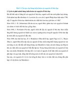
3) Oversteering & Understeering
Left Understeer
uc
a
tio
na
lU
●
se
With unstable driving conditions, understeering and oversteering can occur. Understeering refers to a state
in which the vehicle's turn angle is larger than the steering wheel angle, and the vehicle slides out when
turning a corner. Oversteering refers to a state in which the vehicle's turn angle is smaller than the steering
wheel angle when turning a corner.
a An obstacle appears ahead on the right. The driver turns the steering wheel to the left, but
understeering occurs and the vehicle keeps moving forward toward the obstacle.
Ed
b ESC HECU detects the understeer through the steering angle sensor and Yaw-rate sensor, and
instantly brakes the rear left wheel.
Fo
r
c Consequently, the vehicle is guided into the driver's intended direction.
74
Basic Chassis Technology
Textbook
Right Oversteer
O
nl
y
●
Module3 ESC (Electronic Stability Control)
a After avoiding the obstacle, the driver of the vehicle turned the steering wheel to the right to
remain in the left lane. But the rear wheel lost grip and the rear of the vehicle started to oversteer
towards left.
se
b ESC HECU detects the oversteer through the steering angle sensor and Yaw-rate sensor, and
instantly brakes the front left wheel.
lU
c Consequently, the vehicle is guided into a straight line without skidding.
na
TIP
Vehicle without ESC
Fo
r
Ed
uc
a
tio
If a driver suddenly turns the steering wheel to evade an object that suddenly appeared in front while
driving on a highway in a vehicle without ESC, the action causes the vehicle to slide and becomes
uncontrollable.
Basic Chassis Technology
75
Textbook
Fo
r
Ed
uc
a
tio
na
lU
se
O
nl
y
Module3 ESC (Electronic Stability Control)
76
Basic Chassis Technology
Textbook
Module3 ESC (Electronic Stability Control)
System Components
3.2.1
Main Components
uc
a
tio
na
lU
se
O
nl
y
3.2
Configuration
Wheel Speed Sensor
Yaw Rate Sensor
Ed
Steering Angle Sensor
Function
Detects the speed of each wheel.
Measures the rotation angle of the vehicle via vertical axis.
Detects the driver's directional intention.
Pressure Sensor
Measures brake pressure to identify the driver's braking intention.
ESC OFF Switch
ESCcan be stopped at the driver's will.
This switch is mounted on the pedal assembly and is used to send the status
of the brake pedal to the HECU.
ESC HECU
Receives signal from each sensor and computes the signals and uses the
data to engage brake for each wheel.
Fo
r
Brake Switch
Warning Lamp
Basic Chassis Technology
ABS / EBD / ESC / DBC Notifies system trouble to the driver.
77
Module3 ESC (Electronic Stability Control)
3.2.2
Textbook
Wheel Speed Sensor
se
O
nl
y
1) Exploded View of Wheel Speed Sensor and Its Role
na
lU
The wheel speed sensor detects the speed of each wheel, then transfers the information to the ESC HECU
to calculate the vehicle speed and determine whether the wheel is locked or not. It is located in the wheel
hub area. There are two types of WSS: Passive (Coil Type) and Active (Hall IC Type). Active WSS is not
affected by air gaps and detections can be made from a speed of 0km/h; as such, active WSS is in wider
use than passive WSS.
tio
2) Coil Type & Hall IC Type
Ed
Type
Coil Type
Hall IC Type
uc
a
Category
Hall IC
Base Signal
Voltage
Current
Power Supply
Not required
Required
The magnetic flux may be alternated
upon the rotating of tone wheel and
it energizes the coil.
The internal resistance of Hall IC may be
alternated upon the rotating of tone wheel
and it generates the different current.
Fo
r
Coil
Output
Waveform
Mechanism
78
Basic Chassis Technology
Textbook
3.2.3
Module3 ESC (Electronic Stability Control)
Yaw-rate & 2 G-Sensor
O
nl
y
1) Exploded View of Yaw-rate & 2 G-Sensor and Its Role
lU
se
Yaw-rate sensor measures the rotation angle speed based on the vehicle's vertical axis, side way
acceleration caused by centrifugal force, and longitudinal acceleration for determining sudden braking
or road incline. It sends the data signal to ESC HECU, which uses the data for vehicle stability control.
Yaw-rate sensor includes latitude and longitudinal acceleration sensors that allows all condition detection
with a single sensor. It's data is also used for ESC auxiliary functions or for EPB. Install the Yaw-rate
sensor at the bottom of the center floor console facing ahead.
Ed
uc
a
tio
na
2) Mechanism
Fo
r
Alternating voltage causes the oscillator of the Yaw-rate sensor to transform and oscillate left and right
at a set rate. If the vehicle makes a turn at a constant angular velocity in this state, the detector in the
sensor tilts toward the direction of the oscillation and at a right angle, due to Coriolis force, and produces
alternating voltage. An AC waveform is generated from the detecting element and is used to detect the
cornering direction and magnitude, outputting an analog signal in the process.
Basic Chassis Technology
79
Module3 ESC (Electronic Stability Control)
3.2.4
Textbook
Steering Angle Sensor
O
nl
y
1) Exploded View of Steering Angle Sensor and Its Role
lU
se
Steering Angle Sensor is integrated with Torque Sensor. It detects the the steering wheel turn angle and
torque to determine driver's steering intention. ESC HECU compares the steering wheel angle received
from the steering angle sensor with the vehicle's actual turn angle received from the yaw rate sensor to
determine understeer/oversteer.
Installation locations are as follows.
na
There are two types of steering wheel sensor: optical type and magnetic type. Generally, optical type is
used for low output models, and magnetic type is used for high output models.
tio
▪ In case of vehicles with MDPS.: The Steering angle sensor is installed in MDPS assembly.
uc
a
▪ Vehicle without MDPS: The Steering angle sensor is installed upper side of the clock spring of steering
wheel.
2) Magnetic Sensor and Optical Sensor
Magnetic Sensor
Fo
r
Ed
●
A magnetic sensor is made up of a steering angle detection unit and torque detection unit, which use
the magnets in the main gear, planetary gear and input shaft rotor to detect steering angles and torque.
The steering angle detector is composed of one main gear and two planetary gears. The torque detector
is composed of an input shaft rotor (magnet) and an output shaft rotor. For the steering angle, the main
gear matches the column shaft, rotating two planetary gears that each have a different number of gear
teeth. Then, a phase difference is created and the rotation angle is detected via Hall IC which uses that
80
Basic Chassis Technology
Textbook
Module3 ESC (Electronic Stability Control)
difference. For torque, a magnet mounted on the input shaft rotor rotates due to the distortion of the
torsion bar when cornering. When rotating, the intensity of the magnet field varies, and the consequent
output voltage is detected by the Hall IC. Torque sensors without the steering angle sensor function
have the same mechanism as integrated steering angle/torque sensors.
Optical Sensor
se
O
nl
y
●
Fo
r
Ed
uc
a
tio
na
lU
An optical sensor uses light for detection and is made up of a quill shaft, dust cover, light guide,
input/output disk and PCB assembly. If the light emitting element (LED A/B) generates light, it passes
through two input/output discs via a light pipe. The light is then received by the photodetector in
PCB and a steering angle and torque are detected based on the volume of light received. When the
input/output disc is in a neutral state, the left and right angles are identical, so the amount of light that
passes through it is the same. However, when steering is applied, one side of the disc is blocked, and
the amount of light is reduced. The angle and distortion are determined by the change in light. The
key here is the base point of the input shaft disc, called the index point. If the MDPS is replaced, the
steering angle value which is transmitted to the ECU is different from the steering angle of the actual
vehicle, so set to zero point the steering angle sensor to find the index point.
Basic Chassis Technology
81
Module3 ESC (Electronic Stability Control)
3.2.5
Textbook
ESC OFF Switch
O
nl
y
1) Exploded View of ESC OFF Switch and Its Role
The ESC off switch allows the driver to stop ESC. When the "off" signal is sent to HECU, the ESC OFF
indicator comes on. The ESC off switch is used in the following circumstances.
se
▪ Rocking to free the vehicle in deep snow or loose surface material
▪ Operation of the vehicle on a brake test bench
na
2) ESC 2–Step OFF Switch
lU
▪ Driving with snow chains
ESC Step 1 OFF
Fo
r
●
Ed
uc
a
tio
Improving from the conventional ESC on/off switch, late-model vehicles have a 2-step ESC control switch.
Turning ESC off by one step (semi-ESC) only turns off engine control for sporty acceleration after making
a turn and escaping puddles without reduced engine torque from spinning.
• Switch: Press ESC OFF for less than 3 seconds
• Indicator & buzzer: ESC OFF indicator on, no buzzer
• Display: "Traction control off" displayed on dashboard
• Control: Engine torque control (TCS) OFF, brake control on
●
ESC Step 2 OFF
• Switch: Press and hold ESC OFF for more than 3 seconds
• Indicator & buzzer: ESC OFF indicator on, dashboard buzzer sounded once
• Display: "VDC off" displayed on dashboard
• Control: Engine torque control (TCS) off, brake control off
82
Basic Chassis Technology
Textbook
3.2.6
Module3 ESC (Electronic Stability Control)
Brake Switch
O
nl
y
1) Exploded View of Brake Switch and Its Role
lU
se
When the brake pedal is depressed, current is fed via the brake light switch to the control module. The
Brake Switch Signal is required for monitoring the Pressure Sensor. Usually the Pressure Sensor should
recognize an increase in pressure when the brake pedal is applied (Brake Switch Status ON). And The
brake light switch indicates brake pedal status to the ABS control unit.
Fo
r
Ed
uc
a
tio
na
The stop lamp switch signal is required for the hydraulic brake assist, electronic stability, downhill brake
control and hill start assist function. Furthermore the brake signal is required for the pump motor test which
is performed at speeds above 30km/h every time the ignition is turned on.
Basic Chassis Technology
83
Module3 ESC (Electronic Stability Control)
3.2.7
Textbook
ESC HECU
1) Overview
ESC HECU is composed of HCU, which controls the hydraulic pressure, and ECU, which controls the
HCU and electrical controls. Both components are integrated as a single unit and is mounted in the engine
compartment. Control mechanism is as follows.
▪ ECU identifies the driver's intention. (steering wheel position + vehicle speed + accel pedal)
O
nl
y
▪ ECU analyzes the vehicle's movement. (vehicle turning speed + side pulling force)
▪ Significant inconsistency between the driver's intention and vehicle movement is recognized as a safety
hazard and hydraulic control devices adjust the braking of individual wheels. It also controls the engine
output via communication line connected to the engine to safely control the vehicle out of a potentially
dangerous situation. The indicators and warning lamps are also controlled according to vehicle state.
Ed
Configuration
uc
a
tio
na
lU
se
2) Components
ECU
Receives signals from input elements and produces control signals if a spin,
understeer or oversteer is detected.
HCU
Hydraulic regulator
Motor
Powers the pump with power supplied by ECU.
Pump
Pump is engaged by motor during decompression and returns the oil back to the
master cylinder.
Pressure Sensor
Measures brake pressure to identify the driver's braking intention. Detects sudden
braking from pressure drops.
Solenoid Valve
Receives Open and Close commands from ECU and opens/closes flows for
individual wheel pressure control.
Fo
r
84
Function
Basic Chassis Technology
Textbook
Module3 ESC (Electronic Stability Control)
●
se
O
nl
y
3) Hydraulic Circuit
Configuration
lU
• Inlet Solenoid Valve (ISV)
• Outlet Solenoid Valve (OSV)
na
This valve connects or disconnects the hydraulic path between master cylinder and the wheel
cylinders. The valve remains normally open but it is closed when the dump and hold mode begins
during ABS operation. Purpose of the check valve is to help the brake fluid returning from the wheel
cylinder to the master cylinder when the brake pedal is released.
tio
The outlet solenoid valves are normally closed. The valve is opened when the dump mode begins to
release the wheel cylinder pressure.
uc
a
• Electric Shuttle Valve (ESV)
The Electric Shuttle Valve is normally closed. When ESC is in progress, the valve is opened and
brake fluid is supplied to the pump elements.
• Traction Control Valve (TCV)
Fo
r
Ed
The Traction Control Valve is normally open and the brake pressure from the master cylinder is applied
to the wheel cylinders. While TCS or ESC is in progress, the TCV is closed and the generated pressure
is applied to the front wheel cylinders without returning to the master cylinder. The TCV includes a
relief valve and a check valve. When excessive pressure is supplied from the motor, the relief valve
is opened and the pressure is relieved.
• Pressure Sensor (P/U)
The Pressure Sensor monitors the pressure of the brake line. This sensor signal is the basic data for
hydraulic brake assistance control. Additionally this sensor input is required when ESC is in progress.
Basic Chassis Technology
85
Module3 ESC (Electronic Stability Control)
Normal Braking
O
nl
y
●
Textbook
se
During normal braking, brake pressure is applied to the wheel cylinder via the open Traction Control
Valves (TCV) and Inlet Solenoid Valves (ISV). The Outlet Solenoid Valve remains closed.
lU
This diagram is also showing the fail safe condition of the brake system, as none of the valves is
electrically on under this condition.
na
• Solenoid Valve Operation
Valve
Electrically
Condition
OFF
closed
OFF
open
OFF
open
OFF
open
OSV (LR)
OFF
closed
OSV (RF)
OFF
closed
TCV
ISV (LR)
Fo
r
Ed
uc
a
ISV (RF)
tio
ESV
86
Basic Chassis Technology
Textbook
ABS Braking
se
O
nl
y
●
Module3 ESC (Electronic Stability Control)
• Solenoid Valve Operation
Valve
tio
- Normal braking
na
lU
During ABS operation brake pressure is applied from the master cylinder via the normally open Traction
Control Valves (TCV). The Inlet Control Valves and Outlet Control Valves are driven in a pulsed
cycle, creating the effect of „applying“ (Hold mode) and „releasing“ (Dump mode) the brake(s) of the
appropriate wheel(s). The accumulators inside the Hydraulic Control Unit are damping the pulsation
of the pressurized brake fluid when the Outlet Control Valve (OCV) is opened. The pump draws the
brake fluid out of the accumulators.
Electrically
Condition
OFF
open
ISV
OFF
open
OSV
OFF
closed
ESV
OFF
closed
Valve
Electrically
Condition
TCV
OFF
open
ISV
ON
closed
OSV
OFF
closed
ESV
OFF
closed
Valve
Electrically
Condition
TCV
OFF
open
ISV
ON
closed
OSV
ON
open
ESV
OFF
closed
Ed
uc
a
TCV
Fo
r
- Hold mode
- Dump mode
Basic Chassis Technology
87
Module3 ESC (Electronic Stability Control)
ESC Braking
O
nl
y
●
Textbook
uc
a
- Primary circuit
tio
• Solenoid Valve Operation
Valve
Electrically
Condition
TCV
ON
closed
ESV
ON
open
ISV (LR)
OFF
open
ISV (RF)
ON
closed
OSV (LR)
OFF
closed
OSV (RF)
OFF
closed
Valve
Electrically
Condition
TCV
ON
closed
ESV
ON
open
ISV (LR)
OFF
open
ISV (RF)
ON
closed
OSV (LR)
OFF
closed
OSV (RF)
OFF
closed
Ed
Fo
r
na
lU
se
In this position the Inlet Solenoid Valve(s) (ISV) of the appropriate wheel(s) is/are driven in a pulsed
cycle. The remaining ISV´s are electrically turned on (closed). The Traction Control Valve of the brake
circuit is almost closed (PWM control). The Outlet Control Valves (OCV) remains closed. The Electrical
Shuttle Valve (ESV) is opened to allow the pump to draw brake fluid out of the master cylinder. The
pressurized fluid passes via the pulsed driven rear left Inlet Solenoid Valve (ISV) to the wheel brake
cylinder. The Inlet Solenoid valves of the remaining brake cylinders remain closed. As you can see on
the drawing, also the ESV and TCV of the second brake circuit are in the open position. This is done
to prevent an excessive pressure built up within the circuit. The pump basically pumps the brake fluid
through the pipes without creating pressure.
- Secondary circuit
88
Basic Chassis Technology
Textbook
Module3 ESC (Electronic Stability Control)
3.2.8
Warning Lamp & Indicator Lamp
se
O
nl
y
1) Overview
na
lU
ESC HECU engages Indicator Lamp/Warning Lamp control to check operation status of
ABS/EBD/ESC/DBC systems and alerts the driver in case of malfunction. All the Indicator Lamps/Warning
Lamps are turned ON for 3 seconds when switched to IG ON Mode or when the engine is started. This
is a self-diagnosis process. If all the system is normal, the warning lamps turn OFF. If any of the lamps
remain turned ON, it signifies failure of the corresponding system.
Configuration
tio
2) Indicator/Warning Lamp Function
Function
ESC indicator blinks when the ESC system is on. ESC warning lamp switched
on when the ESC system is faulty.
ESC OFF Warning
Lamp
The ESC off switch allows the driver to stop ESC. When the "off" signal is sent
to HECU, the ESC OFF indicator comes on. ESC can be disabled for sporty
driving and vehicle inspections.
uc
a
ESC Warning Lamp
As the EBD system uses brake warning lamps, brake force is not distributed
to front and rear wheels if the ABS warning lamp and brake warning lamp are
on at the same time.
DBC Indicator
Pressing DBC On turns on the indicator to show that DBC is ready for use
(stand-by); the indicator blinks when DBC is on. The indicator turns red if the
DBC system is faulty.
ABS Warning Lamp
The ABS warning lamp staying on while driving indicates an ABS fault.
However, the brakes continue to function normally.
Fo
r
Ed
EBD Warning Lamp
Basic Chassis Technology
89
Textbook
Fo
r
Ed
uc
a
tio
na
lU
se
O
nl
y
Module3 ESC (Electronic Stability Control)
90
Basic Chassis Technology
Textbook
Maintenance
se
O
nl
y
3.3
Module3 ESC (Electronic Stability Control)
tio
na
lU
Figure 3-1 ESC S / W Management
3.3.1
uc
a
Figure 3-2 MDPS S / W Management
Variant Coding
Ed
1) Purpose
Fo
r
The variant is written into the EEPROM of the ABS/ESCCM. According to the vehicle parameter, the
ABS / ESC software changes. ABS / ESC receives data for variant coding such as engine type, engine
displacement and AT type. The ABS / ESCCM writes the proper variant code on to the EEPROM based
on the received data.
2) Advantages
▪ Creating one software for all variants of vehicle
▪ Every variant of a vehicle has its own application Software
▪ Differences may be small but a new application is needed for comfort
▪ Including all variants in one Software can be done by variant coding (max. 30 variants per Software)
▪ Variant Coding helps avoiding additional costs
Basic Chassis Technology
91
Module3 ESC (Electronic Stability Control)
3.3.2
Textbook
HECU Air Bleeding
O
nl
y
1) Purpose
lU
se
HECU air bleeding prevents vapor lock (spongy brakes). Vapor lock can occur when bubbles form in brake
fluid from heat or from an oil shortage. HECU air bleeding is performed during brake lines maintenance or
a part replacement due to brake fluid leakage.
2) Procedure
Working in a Pair (GDS X)
na
●
tio
a Personnel 1 uses a vacuum pump to drain the clutch fluid from the clutch master cylinder reservoir
tank.
uc
a
If no vacuum pump is available, Personnel 2 removes the air bleeding screws
from the release cylinder and Personnel 1 continuously applies the clutch
pedal to discharge all the clutch fluid. As the clutch master cylinder has no
pressure at this time, the clutch pedal will not return to its original position
when pressed down. Hold the pedal in the hand and repeat pressing down
and pulling up.
NOTE
Ed
b Personnel 1 fully fills the master cylinder reservoir tank with clutch fluid.
c Repeat step 1 and 2 if clutch fluid change is the objective.
Fo
r
d Tighten the air bleeding screws in the clutch release cylinder if clean clutch fluid seeps through
them.
e Repeat pressing down and pulling up the clutch pedal until sufficient pressure has formed, and
then press down and hold the pedal.
f
At this time, Personnel 2 undoes the air bleeding screws in the clutch release cylinder, checks for
air or clutch fluid leakage and immediately tightens them back up.
g Personnel 1 pulls the clutch pedal up with the hand.
h Repeat step 5.
i
Repeat step 6. Stop repeating the steps if air-free clutch fluid comes out.
j
Repeat step 5 and 6 once or twice if normal pressure can be felt when working the clutch pedal.
k Personnel 2 fully tightens the air bleeding screws in the clutch release cylinder. Personnel 1 fills
clutch reservoir tank with clutch fluid up to the maximum line.
l
92
Perform a test run, find a good clutching point and adjust the master cylinder push rod.
Basic Chassis Technology
Textbook
●
Module3 ESC (Electronic Stability Control)
Using Equipment (GDS)
a Prepare the necessary equipment. Connect the power cord to a power socket and turn on the
switch (electric motor-type) or connect the air hose (air-type).
b Open the cap on the clutch master cylinder reservoir tank. Install a clutch fluid pressurizing
adaptor and connect the pressure hose. Set the pressure to 2-3 kg/cm2. Excess pressure will
cause the reservoir tank to rupture.
c Loosen the air bleeding screws in the clutch release cylinder by one turn. Plug in the adapt of the
equipment and insert the vacuum hose in the adaptor.
O
nl
y
d Switch on the equipment. If clean bubble-free clutch fluid comes out of the transparent vacuum
hose line, tighten the air bleeding screws in the clutch release cylinder.
Fo
r
Ed
uc
a
tio
na
lU
se
e Remove the vacuum hose (inserted in the adaptor) from the release cylinder air bleeding screws.
Switch off the equipment. Wait five minutes and remove the adaptor and clutch fluid pressurizing
hose from the master cylinder (not waiting for long enough will cause pressurized clutch fluid to
spurt out).
Basic Chassis Technology
93