Module 2 4WD (TRUYỀN LỰC BỐN BÁNH CHỦ ĐỘNG(BẢN TIẾNG ANH )
Bạn đang xem bản rút gọn của tài liệu. Xem và tải ngay bản đầy đủ của tài liệu tại đây (1.83 MB, 34 trang )
Textbook
Module2 4WD (Four Wheel Drive)
Module2 4WD (Four Wheel Drive)
LESSON
2.1
Overview .............................................................................................................................37
O
nl
y
2.1.1 Introduction....................................................................................................................... 37
2.1.2 4WD Types....................................................................................................................... 38
2.1.3 History of 4WD ................................................................................................................. 39
Components .......................................................................................................................41
Main Components & 4WD Layout .................................................................................... 41
Transfer Case................................................................................................................... 43
Rear Differential ............................................................................................................... 44
Driveline ........................................................................................................................... 45
4WD ECU......................................................................................................................... 46
lU
2.2.1
2.2.2
2.2.3
2.2.4
2.2.5
se
2.2
2.3
na
2.2.6 4WD Coupling .................................................................................................................. 47
2.2.7 4WD Lock Switch ............................................................................................................. 48
2.2.8 4WD Lock Lamp & Warning Lamp ................................................................................... 49
Control ................................................................................................................................51
2.4
tio
2.3.1 In / Output Elements......................................................................................................... 51
2.3.2 Coupling Control Mode..................................................................................................... 52
4WD Type Comparison......................................................................................................53
uc
a
2.4.1 Comparison ITM & ITCC & DEHA.................................................................................... 53
2.4.2 ITM (Interactive Torque Management) ............................................................................. 54
2.4.3 ITCC (Intelligent Torque Controlled Coupling).................................................................. 58
2.4.4 DEHA (Direct Torque Controlled Coupling) ...................................................................... 61
2.5
Maintenance .......................................................................................................................65
Fo
r
Ed
2.5.1 Towing of 4 WD Vehicles.................................................................................................. 65
2.5.2 Precautions (Only DEHA)................................................................................................. 66
[Learning Objectives]
▪ Explain the function of each of the four types of 4WD.
▪ Describe the system layout and list the locations, mechanisms and functions of components.
▪ Explain the difference between ITM, ITCC and DEHA.
▪ Take necessary actions after a part change and list the cautionary measures required for
maintenance.
Basic Chassis Technology
35
Textbook
Fo
r
Ed
uc
a
tio
na
lU
se
O
nl
y
Module2 4WD (Four Wheel Drive)
36
Basic Chassis Technology
Textbook
Module2 4WD (Four Wheel Drive)
2.1
Overview
2.1.1
Introduction
The main reason for the usage of 4 WD system is to improve the overall traction of the vehicle.
tio
na
lU
se
O
nl
y
For easy understanding we define traction as the maximum amount of driving force the tire can apply
against the ground. The major benefit of a four-wheel drive is the potential to double the amount of
longitudinal force the tires can apply to the ground. This helps in a variety of situations, such as low
friction road (e.g. snow covered road).
uc
a
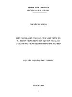
Figure 2-1 Comparison between 2WD and 4WD
Fo
r
Ed
In the example on the right side a road with a partly slippery surface is given. In the case of a 2 WD vehicle
the required torque to move the vehicle is higher than the available traction. As a result the wheels start
spinning and the vehicle gets stuck. A 4 WD vehicle on the same spot will transfer more torque to the rear
wheels on the not slippery part, so that the torque acting at the front wheels and rear wheels is below the
available traction: the vehicle will move forward. (simplified general sample: the exact condition of torque
transfer depends on the actual system layout). The following factors affect traction in general: the weight
on the tire - The more weight acts on a tire, the more traction is available.
The coefficient of friction relates the amount of friction force between two surfaces to the force holding the
two surfaces together: it is a function of the kind of tires on the vehicle and the type of surface the vehicle
is driving on. Important the coefficient of friction for static contact is higher than for dynamic contact (wheel
slip), therefore static contact provides better traction than dynamic contact. Wheel slip: it occurs when the
force applied to a tire exceeds the traction available to that tire. The possible traction force is reduced in
this case, as explained before. The weight transfer due to vehicle acceleration and cornering influences
the possible traction of the tires, as the weight acting on the individual tire changes.
Basic Chassis Technology
37
Module2 4WD (Four Wheel Drive)
4WD Types
O
nl
y
2.1.2
Textbook
Fo
r
Ed
uc
a
tio
na
lU
se
These are some possible and commonly applied layouts of 4WD systems. The reason for the availability
of different system is the different usage of vehicles and of course also the cost of the vehicle, as a
sophisticated full time four wheel drive system is much more expensive then a simple one or a 2 WD .
Other differences in the constructions may depend for example on the base vehicle, whether it is a front
wheel drive or a rear wheel drive vehicle. Also to consider is the general type of vehicle and its foreseen
usage, for example a sporty passenger car or a pick up used for heavy duty operation etc. Cars which are
designed for heavy duty generally have a reduction section incorporated in the drive line to increase the
available torque if necessary. Having the cost advantage the demerit of a part time system is that it should
not be driven in 4 WD mode on a road with good friction co efficient. As there is no center differential,
the whole driveline is put under stress under this condition, which causes wear and noise. A full time
four wheel drive generally is equipped with a center differential( or in rare cases with a viscous coupling
instead), and therefore can be used also on a dry road in 4 WD mode without any problem. The same
is valid for the all wheel drive or permanent four wheel drive. The difference is that the 4 WD can not be
switched off. In case of the All wheel drive there is no high and low section in the transfer, as the vehicles
are designed for on road use only. Please note that the terms given above might be used different for
example depending on the manufacturer. Recently electronically controlled system are developed, which
use the 4WD automatically and only in the case it is required.
38
Basic Chassis Technology
Textbook
2.1.3
Module2 4WD (Four Wheel Drive)
History of 4WD
→
EST (Selective 4WD)
TOD (Constant 4WD)
ITM & ITCC & DEHA
→
▪ Switch ON: FW/RW
power distribution fixed
at 50:50 (speed 40km/h↑:
power distribution
automatically changed to
100:0)
tio
1) EST (Electric Shift Transfer)
▪ Switch OFF: AUTO mode
on
na
lU
▪ 4H ↔ 4L: Activate switch
after stopping
4H ↔ 4L: Activate switch
after stopping
se
▪ 2H ↔ 4H: Moving vehicle
O
nl
y
(Constant 4WD)
▪ 4WD mode
uc
a
EST is standard on all models and trims for part-time 4WD, allowing drivers to “shift on the fly” between
two- and four-wheel-drive modes at speeds up to 80 km/h.
• 2H mode: For normal road conditions (driving power of 0:100, HIGH mode)
• 4H mode: For slippery road conditions, e.g. unpaved, snow and rain (driving power of 50:50, HIGH
Ed
mode)
• 4L mode: For getting out of rough roads and when maximum towing power is required (driving
Fo
r
power of 50:50, LOW mode)
2) TOD (Torque On Demand)
TOD electronically transfers power and torque from the rear to the front as required, enhancing off-road
traction, handling agility and steering precision.
▪ 4WD mode
• AUTO mode: Used for normal road conditions or slippery roads, i.e. snow or rain (driving power
distributed automatically)
• LOW mode: For getting out of rough roads and when maximum towing power is required (driving
power of 50:50, LOW mode)
Basic Chassis Technology
39
Module2 4WD (Four Wheel Drive)
Textbook
3) ITM & ITCC & DEHA
ITM (Interactive Torque Management), ITCC (Intelligent Torque Controlled Coupling) and DEHA (Direct
Electro Hydraulic Actuator) are essentially identical technologies, with only their names and components
varying by manufacturer. The differences will be explained in detail in a section to follow.
These three systems, like TOD, are electronic constant 4WD modes, but of a reduced size and with
improved controllability. There is no LOW mode for selection. Turning the switch on fixes the front/rear
wheel driving power at 50:50.
O
nl
y
▪ 4WD mode
• 4WD LOCK mode: For slippery road conditions, e.g. unpaved, snow and rain (driving power of
Fo
r
Ed
uc
a
tio
na
lU
se
50:50, HIGH mode)
40
Basic Chassis Technology
Textbook
Module2 4WD (Four Wheel Drive)
Components
2.2.1
Main Components & 4WD Layout
uc
a
tio
na
lU
se
O
nl
y
2.2
Ed
1) Configuration
Fo
r
4WD system is based on a front wheel drive power train and consists of the following main parts : transfer
case, propeller shaft, the coupling unit and rear differential on the mechanical side and the control module,
the 4WD lock switch, the throttle position sensor, the wheel speed sensors, the steering angle sensor the
4 WD lock lamp and the malfunction lamp.
When the 4WD lock is activated (possible up to a certain speed only) the coupling is fully activated and
the vehicle is in 4WD mode (50:50), indicated by the 4WD lock lamp. As there is no center differential
tight corner wind up will occur in this condition. In standard mode (lock switch off) the torque distribution
between front and rear axle is controlled based on the inputs from the throttle position sensor, wheel speed
sensors and the steering angle sensor. As 4WD condition is only used when required (basically : wheel
slip detected) the fuel consumption is reduced compared to a standard all wheel drive vehicle. In the case
of a problem in the system the driver is informed by the malfunction lamp.
Basic Chassis Technology
41
Module2 4WD (Four Wheel Drive)
Textbook
O
nl
y
2) Layout
lU
se
The transfer case consists of the input shaft driven via the front differential by the means of splines and a
gear train to supply the torque to the propeller shaft. The input shaft of the transfer is hollow, so that the
drive shaft of the right side front wheel can be passed trough it and connected to the front differential. The
gear train is used change the input shaft speed to the speed value required at the rear axle and to change
the direction of the output towards the propeller shaft.
Fo
r
Ed
uc
a
tio
na
The gear train consists of two conventional gears, a ring gear and a bevel gear. With active ITM coupling
the power is transferred via the gear train, the propeller shaft, the activated 4WD coupling to the rear
differential and finally to the rear wheels. In the case the 4WD coupling is not activated the gears in the
transfer and the propeller shaft turn free and only the front wheels are driven.
42
Basic Chassis Technology
Textbook
2.2.2
Module2 4WD (Four Wheel Drive)
Transfer Case
Fo
r
Ed
uc
a
tio
na
lU
se
O
nl
y
A transfer is normally fitted in the transaxle of front wheel drive vehicles, and changes the direction of
movement to deliver driving power to the rear wheels. The oil to be used for the transfer should be gear
oil (SAE 75W/90 API GL-5 grade), which should be inserted to fill up under the oil port.
Basic Chassis Technology
43
Module2 4WD (Four Wheel Drive)
2.2.3
Textbook
Rear Differential
O
nl
y
1) Purpose of Differential
Vehicles which are not equipped with a center differential but only with the front and rear differential should
only be used in 4 WD under specific conditions, such as slippery road.
na
lU
se
Driving this type of vehicle in 4 WD on try paved road will cause high stress to the tires and the drive line.
This can be easily recognized during cornering, as the 1) Purpose of Differential driver will notice a wind
up of the chassis and a high resistance against rolling. This is caused by the fact that the rear wheels and
the front wheels travel a different distance during cornering, as indicated in the picture. The only way to
compensate this without center differential is a (slightly) slipping tire. Due to the high friction co efficient
of a try road, a high force is required before the tire starts slipping, therefore the stress on the drive line is
high.
Fo
r
Ed
uc
a
tio
2) Principle
A simple, conventional 4WD system with standard (open) differentials still can loose traction relatively easily
under certain conditions. An open differential can send only the amount of torque to the tires that won't
cause the tire with the least traction to slip. The transferable torque therefore might not be enough to get
the car out of stuck condition if both axles are on a slippery surface (as indicated in the picture) , because
the tires on it will start to slip. In the shown situation this would mean that both right side wheels will spin
and the car will not move. As this is not desirable for real off road use, there are some ways to improve a
system like this.
44
Basic Chassis Technology
Textbook
2.2.4
Module2 4WD (Four Wheel Drive)
Driveline
1) Drive Shaft
Drive Shaft transmits the driving power from the engine and transaxle to the wheels.
2) Propeller Shaft
Fo
r
Ed
uc
a
tio
na
lU
se
O
nl
y
Propeller shaft transmits the driving power from the engine and transaxle to rear wheels and optimizes
driving power while driving. A universal joint, C/V joint and rubber coupling make up a propeller shaft.
Basic Chassis Technology
45
Module2 4WD (Four Wheel Drive)
2.2.5
Textbook
4WD ECU
Fo
r
Ed
uc
a
tio
na
lU
se
O
nl
y
The 4WD ECU, based on the signals received from various sensors, determines the road surface and
driving conditions and precisely adjusts the clamping force of the 4WD coupling muti-plate clutch to variably
regulate the portion of driving power transmitted to the rear wheels. Its location differs by 4WD type.
46
Basic Chassis Technology
Textbook
2.2.6
Module2 4WD (Four Wheel Drive)
4WD Coupling
O
nl
y
The application of 4WD couplings largely depends on the type of system in use. Further information will
be provided in the System Types section to follow. In this chapter, the concept of 4WD couplings will be
outlined using the viscous coupling as an example.
se
Figure 2-2 4WD Coupling according to Types
tio
na
lU
Let’s have a closer look to the operation of a viscous coupling this is EST system’s coupling. It is commonly
used to link the back wheels to the front wheels so that when one set of wheels starts to slip, torque will
be transferred to the other set. Therefore as a sample lets have a look at a viscous coupling between the
front and rear axle.
Fo
r
Ed
uc
a
Figure 2-3 Location of ITM Coupling
Figure 2-4 Structure of a Coupling (left) / Mode of Power Transmission (right)
When one set of wheels starts to spin faster, for example because it is slipping, the set of plates connected
to those wheels spins faster than the others. The viscous fluid between the plates, tries to catch up with
the faster disks, dragging the slower disks along. This transfers torque to the slower moving wheels: the
wheels that are not slipping. The higher the speed of the plates is relative to each other, the more torque
the viscous coupling transfers from one set to the other.
Basic Chassis Technology
47
Module2 4WD (Four Wheel Drive)
4WD Lock Switch
O
nl
y
2.2.7
Textbook
Fo
r
Ed
uc
a
tio
na
lU
se
Pressing the LOCK mode switch turns on the 4WD LOCK lamp on the crashpad. The 4WD ECU then
activates the actuator inside the coupling to fix the proportions ratio of the front/rear wheel driving power
at 50:50. The LOCK mode switch is used to maximize the vehicle's driving power under driving conditions
such as rough terrain, off-road, steep slopes, sandy or muddy roads, etc. When vehicle speed is over 40
km/h, LOCK mode is deactivated and changes to AUTO mode to protect the system and improve drivability
(cluster lamp remains turned on), and when the vehicle speed falls below 40 km/h again, it returns to the
LOCK mode. Driving in AUTO mode is similar to that of 2WD under normal driving conditions, but when the
system determines the conditions require four-wheel driving, the front/rear wheel driving power distribution
is triggered automatically by the ECU, without the intervention of the driver, so that the driving power is
appropriately transmitted to the front/rear wheels.
48
Basic Chassis Technology
Textbook
2.2.8
Module2 4WD (Four Wheel Drive)
4WD Lock Lamp & Warning Lamp
1 When the 4WD system fails, 4WD Warning Lamp flashes on the cluster.
2 Selecting 4WD LOCK mode turns on the 4WD LOCK MODE Lamp on the dashboard.
3 In AUTO mode, there is no indicator.
Fo
r
Ed
uc
a
tio
na
lU
se
O
nl
y
4 The 4WD ECU and the cluster use CAN communication.
Basic Chassis Technology
49
Textbook
Fo
r
Ed
uc
a
tio
na
lU
se
O
nl
y
Module2 4WD (Four Wheel Drive)
50
Basic Chassis Technology
Textbook
Module2 4WD (Four Wheel Drive)
2.3
Control
2.3.1
In / Output Elements
uc
a
tio
na
lU
se
O
nl
y
ITM (Interactive Torque Management), ITCC (Intelligent Torque Controlled Coupling) and DEHA (Direct
Electro Hydraulic Actuator) are essentially identical 4WD technologies, with only their input/output elements
varying slightly by manufacturer. The input/output elements of 4WD will be outlined in this chapter. The
difference between the three manufacturers' technologies will be explained in a section to follow.
All the described operations are controlled by the 4WD ECU. It processes the input signals and controls
the outputs. The following input signals are provided to the ECU.
Ed
Braking condition from Braking Signal/ABS active signal: in 4WD mode all wheels are mechanically
connected therefore a locked wheel would influence all other wheels, leading to a difficult controllable
braking habit of the vehicle. Therefore the 4WD is disabled when the ABS becomes active.
Fo
r
Input torque based on throttle position sensor signal, to decide the right amount of torque distribution (by
duty control of the EMC).
Cornering status from the steering wheel angle sensor to prevent wind up of the drive train during cornering.
The steering angle sensor receives signals through CAN communication with MDPS; if a vehicle has no
MDPS, signals are received from ESC.
Vehicle speed and wheel speed difference (front & rear) from wheel speed sensors to detect slip condition
of the wheels and control the torque distribution accordingly.
All this signals are used to control the duty to the EMC and thereby the torque share of the axles, which
is the main output signal. Other outputs than the EMC control are the 4WD lock lamp, the 4 WD warning
lamp and the diagnosis signal.
Basic Chassis Technology
51
Module2 4WD (Four Wheel Drive)
2.3.2
Textbook
Coupling Control Mode
Normal driving
Cornering
During normal
driving, most of the
driving power is
transferred to the
front wheels.
The driving power
appropriate for the
vehicle’s turning
radius and speed
is transmitted to
the rear wheels.
Wheel slip
Locking
Front/rear Wheel Driving
Power Distribution
AUTO MODE
100:0 - 50:50
(normal driving)
(variable control)
Ed
uc
a
tio
Mode
LOCK MODE
50:50 - 50:50
(rough driving)
(fixed distribution ratio)
Fo
r
52
se
na
2) Driving Power Distribution
Maximizes the
torque on rough
roads (activated
only when the
vehicle speed is
below 40 km/h).
lU
When one or
both front wheels
are slipping, the
driving power
appropriate for
the degree of slip
is transferred to
the rear wheels.
O
nl
y
1) Operation Sequence Depending on Driving Conditions
Description of Operation
The driving power between the front and rear
wheels are variably controlled by the 4WD ECU
control logic depending on the road surface and
driving conditions (quick acceleration, cornering,
etc.).
This mode is used for handling tough conditions,
such as sand, mud, snow, and puddles. With
LOCK mode ON, the system minimizes front/rear
wheel slipping by evenly distributing the driving
power to the front/rear wheels in a 50:50 ratio.
In order to prevent tight corner braking while
cornering, however, it regulates driving power
according to the cornering angle, and sets a
vehicle speed limit condition to avoid danger
due to sudden changes of conditions in the
vehicle running at a high speed. (LOCK mode is
deactivated at the speed of 40 km/h or higher.)
Basic Chassis Technology
Textbook
Module2 4WD (Four Wheel Drive)
2.4
4WD Type Comparison
2.4.1
Comparison ITM & ITCC & DEHA
BorgWarner (US)
JTEKT (Japan)
Wia Magna Powertrain
(ROKorea)
System Name
ITM (Interactive Torque
Management)
ITCC (Intelligent Torque
Controlled Coupling)
DEHA (Direct Electro
Hydraulic)
Applied Model
Tucsan / SM
Tucson ix / Veracruz
DM
Operating
Method
EMC (Electronic Magnetic
Coil)
EMC (Electronic Magnetic
Coil)
Electro-hydraulic motor
type
Operating
Mode
AUTO / 4WD LOCK
AUTO / 4WD LOCK
AUTO / 4WD LOCK
Weight
Approx. 8.0 kg
9.125 kg
8.2 kg
Inspect
ECU / magnetic coil / ball
lamp / wet friction materia
ECU / magnetic coil / ball
lamp / wet friction material
ECU / motor / hydraulic
pump /piston / wet friction
material
Wheel speed sensor
Wheel speed sensor
Wheel speed sensor
SPS
APS SAS
ECU control - magnetic
coil - primary clutch (1st)
- ball lamp - main clutch
(secondary) - Driving
power transferred to
rear wheels
ECU control - motor hydraulic pump - piston
- clutch - Delivers rear
wheel driving power.
ECU control - magnetic
coil - primary clutch (1st)
- ball lamp - Main clutch
(secondary) - Driving
power transferred to
rear wheels
se
uc
a
tio
Operation
Overview
lU
APS SAS
na
Input Sensor
O
nl
y
Manufacturer
Fo
r
Ed
External
Appearance
Basic Chassis Technology
53
Module2 4WD (Four Wheel Drive)
2.4.2
Textbook
ITM (Interactive Torque Management)
1) Introduction
Controllability of the vehicle in all driving situations is becoming an important promotional factor for
All-Wheel-Drive. An AWD vehicle has better road handling and is safer in all driving situations.
O
nl
y
The characteristics of this system is that it is in the 2WD state at constant vehicle speed but it changes the
torque distribution to rear wheels in the 4WD state according to the driving state.
uc
a
tio
na
lU
se
2) Main Components
Ed
As shown in the above diagram, ITM is made up of a transfer case, propeller shaft, electronically controlled
ITM coupling unit, rear differential, control module, 4WD lock switch, throttle position sensor, wheel speed
sensors, steering angle sensor, 4 WD lock lamp and malfunction lamp.
Fo
r
Refer to the preceding portion of this section for the mechanism and components of 4WD. As the
components and mechanism of the coupling, a main component of 4WD systems, differ by system, the
ITM coupling will be explained on the following page.
54
Basic Chassis Technology
Textbook
Module2 4WD (Four Wheel Drive)
3) ITM Coupling
Items
Description
Operating Method
EMC (Electronic Magnetic Coil)
Torque
2,000Nm
Weight
8kg
Housing Material
Aluminum
Oil
Mobil Fluid – LT (0.15L)
Overview
Fo
r
Ed
uc
a
tio
na
lU
se
●
Specification
O
nl
y
●
The heart of the system is the ITM coupling (beside the electronic control unit). The main components
of the coupling unit are the housing and bearings, the electro magnetic coil, the primary clutch, the apply
cam, the steel balls and the secondary clutch. The two clutches are both multi disc type clutches. The
primary clutch is used to create pressure on the secondary clutch via the apply cam.
Basic Chassis Technology
55
Module2 4WD (Four Wheel Drive)
Components
Fo
r
Ed
uc
a
tio
na
lU
se
O
nl
y
●
Textbook
56
Basic Chassis Technology
Textbook
●
Module2 4WD (Four Wheel Drive)
Coupling Operation
• Constant speed drive: almost 2WD state
• Torque distribution (4WD state) changes according to the driving state (ex: sudden start, turning,
at low-mu surface) by the ECU logic
• Basic information: Input torque (Throttle Position Sensor), Steering Angle Sensor, Wheel Speed
Sensor, Brake Signal as well as ABS signal
• EMC Coil energizes to operate the Primary Clutch
O
nl
y
• The amount of electromagnetic force in the Primary Clutch decides displacement of a Base Cam
• Displacement of the Base Cam increases frictional force between Inner Plates and Outer Plates of
the Secondary Clutch
Fo
r
Ed
uc
a
tio
na
lU
se
• While braking: performs a different control logic to get efficient braking
Figure 2-5 EMC Operation
Basic Chassis Technology
57
Module2 4WD (Four Wheel Drive)
2.4.3
Textbook
ITCC (Intelligent Torque Controlled
Coupling)
1) Introduction
Controllability of the vehicle in all driving situations is becoming an important promotional factor for
All-Wheel-Drive. An AWD vehicle has better road handling and is safer in all driving situations.
O
nl
y
The characteristics of this system is that it is in the 2WD state at constant vehicle speed but it changes the
torque distribution to rear wheels in the 4WD state according to the driving state.
The intelligent torque controlled coupling (ITCC) is a trademark of JTEKT - Toyoda Koki Automotive
Systems and is applied as standard on the EN. The ITCC system offers fully controllable torque transfer
characteristics and extremely rapid activation and deactivation of the 4WD system automatically.
Ed
uc
a
tio
na
lU
se
2) Main Components
Fo
r
The 4WD drive line comprises of less parts than other systems, resulting in reduced weight and reduced
fuel consumption. The system is based on a front wheel drive power train and consists of the following main
parts : transfer case, propeller shaft, the electronically controlled ITCC coupling unit and rear differential
on the mechanical side and the control module, the 4WD lock switch, the throttle position sensor, the wheel
speed sensors, the 4 WD lock lamp and the malfunction lamp on the electrical side. When the 4WD lock
is activated the coupling is fully activated and the vehicle is in 4WD mode (50:50), indicated by the 4 WD
lock lamp. Full lock mode is available up to a vehicle speed of 30 km/h.
58
Basic Chassis Technology
Textbook
Module2 4WD (Four Wheel Drive)
3) ITCC Coupling
Items
Description
Operating Method
EMC (Electronic Magnetic Coil)
Torque
1,320Nm
Weight
9Kg
Housing Material
Aluminum
Oil
ATF JWS 3309 (0.13L) – Permanent, No Exchange
Overview
Fo
r
Ed
uc
a
tio
na
lU
se
●
Specification
O
nl
y
●
The heart of the system is the ITCC coupling (beside the electronic control unit). The unit can handle a
output torque of up to 1320Nm and is filled with JWS 3309 ATF oil (same as used in Aisin F21-450 AT)
which is maintenance free. The main components of the coupling unit are the housing and bearings, the
electro magnetic coil, the pilot clutch, the pilot cam, the main cam, the steel balls and the main clutch.
All clutches are multi disc type clutches. The pilot clutch is used to create pressure on the main clutch
via the main cam.
Basic Chassis Technology
59