Module 1 AT (HỘP SỐ TỰ ĐỘNG (BẢN TIẾNG ANH)
Bạn đang xem bản rút gọn của tài liệu. Xem và tải ngay bản đầy đủ của tài liệu tại đây (1.61 MB, 34 trang )
Textbook
Module1 AT (Automatic Transmission)
Module1 AT (Automatic Transmission)
LESSON
1.1
Overview ...............................................................................................................................3
O
nl
y
1.1.1 Introduction......................................................................................................................... 3
1.1.2 Model Range ...................................................................................................................... 4
1.1.3 Specification ....................................................................................................................... 6
1.2
Layout ...................................................................................................................................7
1.3
se
1.2.1 Main Feature ...................................................................................................................... 7
1.2.2 Input & Output Elements .................................................................................................... 8
Components .........................................................................................................................9
1.3.1 Mechanical Components.................................................................................................... 9
Drive Train ..........................................................................................................................23
na
1.4
lU
1.3.2 Hydraulic Control Components ........................................................................................ 13
1.3.3 TCU Input Components.................................................................................................... 16
1.3.4 TCU Output Components................................................................................................. 19
1.5
tio
1.4.1 Clutch & Brake Operation................................................................................................. 23
1.4.2 Power Flow ...................................................................................................................... 24
Maintenance .......................................................................................................................29
Ed
uc
a
1.5.1 Oil Level Adjustment ........................................................................................................ 29
1.5.2 TCM Learning................................................................................................................... 31
1.5.3 Inhibitor Switch Cable Adjustment.................................................................................... 33
[Learning Objectives]
Fo
r
▪ Explain the system mechanism by observing a transmission layout.
▪ List the locations, mechanisms and functions of components.
▪ Explain the power flow in each gear shift by observing the solenoid valve operation chart.
▪ Take necessary actions after a part change and list the cautionary measures required for
maintenance.
Basic Chassis Technology
1
Textbook
Fo
r
Ed
uc
a
tio
na
lU
se
O
nl
y
Module1 AT (Automatic Transmission)
2
Basic Chassis Technology
Textbook
Module1 AT (Automatic Transmission)
1.1
Overview
1.1.1
Introduction
The functions of a transmission are as follows.
▪ Increased driving force when starting off or driving uphill.
▪ Reduced engine rotation speed for increased rotary power.
▪ Reversing a vehicle, as an engine cannot reverse-rotate.
lU
▪ High-speed rotation of wheels during high-speed driving.
se
▪ No load on the engine at startup.
O
nl
y
A transmission is a device that changes and transfers engine power (rotary power and speed) to the wheels
according to a vehicle's driving state. Transmissions come in a manual type and an automatic type. A
transmission is installed between the clutch and propeller shaft or between the clutch and final gear.
Fo
r
Ed
uc
a
tio
na
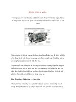
An automatic transmission performs automatic clutch and transmission control, which is manually
performed with a manual transmission. A torque converter, which functions as a clutch, a wet multi-plate
clutch, which controls planetary gears, and a brake band make up an automatic transmission. Because
the engine and power transfer device are connected via a medium in fluid, vibration and shock are
absorbed, and gear shift appropriate for engine output can take place at all times. Compared to the
manual transmission, the automatic transmission consumes approximately 10% more fuel, but many
drivers prefer the automatic transmission for its convenience and ride comfort.
Basic Chassis Technology
3
Module1 AT (Automatic Transmission)
Model Range
lU
se
O
nl
y
1.1.2
Textbook
na
In order to cope with the specific needs for different vehicles and markets Hyundai uses several different
automatic transmissions in the product range, such as:
tio
▪ Model: A163
▪ Model: A4AF3
uc
a
The A163 model is a 3-speed electronic controlled front wheel driven automatic transaxle produced by
AISIN, Japan and there are two divisions as follows. A163-A is for 0.8ε Engine (DOM only) A163-B is
for 1.0ε Engine, Application: MX (Atos, Visto, Atos Prime)
Ed
It is the latest development among the alpha automatic transaxles (advanced alpha A/T). It is a 4-speed
electronic controlled front wheel driven transaxle produced by HMC. Application: X -3, LC (Accent), TB
(Getz), LD,C-car The vehicles equipped an alpha engine)
▪ Model: F4A series and F5A series
Fo
r
The F4A51 model is a HIVEC 4-speed electronic controlled front wheel driven automatic transaxle
produced by HMC and installed on the vehicle that has the engine volume of 2.0L or more. The F5A51
model is a 5-speed electronic controlled front wheel driven automatic transaxle produced by HMC
and is based on the 4 speed version. Depending on the actual vehicle there are several versions
available, such as the A5HF1 for the NF Sonata. Also for the 4 speed transmissions several versions
are available.
W4A51 is a kind of F4A51 HIVEC 4-speed A/T with a 4-wheel drive mechanism. Application: santa Fe
▪ Model: AW30-40LE
The AW30-40LE model is a 4-speed electronic controlled rear wheel driven automatic transmission
produced by AISIN, Japan. Application: HP (Terracan)
4
Basic Chassis Technology
Textbook
Module1 AT (Automatic Transmission)
▪ Model: FRA
It is a 4-speed electronic controlled front wheel driven automatic transaxle produced by JATCO, Japan.
Application: MX (Atos, Visto, Atos Prime)
▪ Model: KM175
It is a Kyoto Model 4-speed electronic controlled front wheel driven automatic transaxle produced by
HMC and there are two divisions as follows. KM175-5 is for 2.0SOHC KM175-6 is for 2.0DOHC Engine.
Application: Y-3(Sonata), Santamo
▪ Model: F21-450
O
nl
y
It is a 6-speed electronic controlled front wheel driven automatic transaxle produced by AISIN, Japan.
The TCM is placed on top of the transaxle housing and all sensors are positioned inside the AT assembly.
Application: EN (Veracruz)
▪ Model: A5SR1/2
se
It is a 5-speed electronic controlled rear wheel driven automatic transmission by JATOCO, Japan,
produced in Korea by Hyundai Power-Tech. Application: H-1 (TQ) CRDi 2.5L, BK (Genesis Coupe) 2.0L
▪ Model: A4CF1/2
lU
It is a 4-speed/5-speed electronic controlled front wheel driven automatic transaxle developed by HMC.
Application: HD (Elantra) 1.6L/2.0L, FD (i30) 1.6L/2.0L
na
▪ Model: B400/B600
▪ Model: 6HP26
tio
It is a 6-speed electronic controlled front wheel driven automatic transaxle by AISIN, Japan. Application:
BH (Genesis) 3.3L/3.8L
uc
a
It is a 6-speed electronic controlled rear wheel driven automatic transmission by ZF, Germany. The
TCM and input sensors are integrated on the valve body. Application: BH (Genesis) 4.6L, BK (Genesis
Coupe) 3.8L
▪ Model: A6LFx, A6MFx
Ed
It is a 6-speed electronic controlled front wheel driven automatic transmission developed by Hyundai
Motor Company. The speed sensors are integrated on the valve body. Application: LM (Tucson, ix35),
YF (Sonata)
▪ Model: 6HP19
Fo
r
It is a 6-speed electronic controlled rear wheel driven automatic transmission by ZF. The TCM and input
sensors are integrated on the valve body. Application: BK (Genesis coupe) 3.8L
Basic Chassis Technology
5
Module1 AT (Automatic Transmission)
1.1.3
Textbook
Specification
A6GF1
A6MF1
Applicable Engines
ν-1.8MPI, γ-1.6 MPI
Lambda- 3.3, 3/8
Allowed Max. Torque (kg.m)
18kgf-m
33.5/45kgf-m
Length (mm)
373
387
73
94
1st
4.4
4.651
2nd
2.726
2.833
3rd
1.834
4th
1.392
5th
1
6th
0.774
O
nl
y
Categories
R
3.44
3.39
Clutch
2 Set (OD, 35R)
Brake
3 Set (UD, LR, 26)
OWC
1 Set
1
0.722
2 Set (OD, 35R)
3 Set (UD, LR, 26)
1 Set
Fo
r
Ed
uc
a
tio
na
Component
1.387
se
Gear Ratio
1.842
lU
Weight (kg)
6
Basic Chassis Technology
Textbook
Module1 AT (Automatic Transmission)
Layout
1.2.1
Main Feature
uc
a
tio
na
lU
se
O
nl
y
1.2
Ed
An automatic transmission is made up of a torque converter, which transfers engine power, a gear device,
which converts power transferred from the torque converter, a hydraulic system, which changes the shift
ratio by changing the gear device configuration, and an electronic control system, which controls the overall
function of an automatic transmission.
Fo
r
An automatic transmission receives signals from various sensors and switches and controls the solenoid
valve, clutch and brakes for converting power received from the torque converter into planetary gear output
appropriate for different gear shifts.
Basic Chassis Technology
7
Module1 AT (Automatic Transmission)
Input & Output Elements
na
lU
se
O
nl
y
1.2.2
Textbook
uc
a
tio
TCU processes signals received from sensors for optimal gear shifts, smoother shifts and improved fuel
efficiency. The input section receives various sensor signals, the control section determines the optimal
gear selection based on sensor signals and controls the hydraulic pressure and the damper clutch, and
the output section executes controls based on TCM commands. TCM functions as follows.
▪ Determines the optimal gear selection using sensor data.
▪ Executes gear shift if the current gear is not the optimal gear (prevent gear shift shock).
Ed
▪ Determines the damper clutch activation – activates and deactivates accordingly.
▪ Regulates the line pressure based on current torque level.
Fo
r
▪ Performs automatic transaxle diagnosis.
8
Basic Chassis Technology
Textbook
Module1 AT (Automatic Transmission)
1.3
Components
1.3.1
Mechanical Components
1) Torque Convertor
O
nl
y
1 Functions and Roles
na
lU
se
A torque converter transfers engine power to a transmission and is made up of an impeller, turbine
and stator. Its functions are as follows.
tio
• Power transfer: Transfers engine power to the transmission
• Torque increase: Torque is increased by a stator to exceed engine-shaft torque
• Oil pump: Rotates the oil pump driver gear to pump oil
uc
a
• Improved fuel efficiency: Engine RPM (power) is transferred to a transmission by a damper clutch
2 Mechanism
• Torque multiplication
Fo
r
Ed
Due to the application of the stator the engine torque can be multiplied. The torque multiplication
is possible because the stator redirects the backflow stream so that it reaches the impeller vanes
having the same direction that the impeller has and works as follows: during starting off the impeller
turns with engine speed and the turbine is on halt. The fluid driven by the impeller reaches the
turbine and transfers the energy (engine torque) to it.
Basic Chassis Technology
9
Module1 AT (Automatic Transmission)
Textbook
• Fluid clutch operation
When leaving the turbine again the fluid flow is redirected by the stator, so that the fluid stream
becomes the same direction then the impeller (engine) is turning. This creates a force which tries to
turn the stator against the impeller (engine) turn direction. Due to the one way clutch this movement
is restricted. Therefore the oil flow is redirected into the engine turn direction. This sharp change in
direction causes a backblock of the fluid. The force created by this acts as additional force on the
turbine (within turning direction), so that its output torque is increased. Another positive effect is that
the fluid which is returned to the impeller reaches it in turning direction and nearly free of vortices.
O
nl
y
2) Damper Clutch
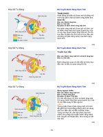
1 Functions and Roles
tio
na
lU
se
Due to the fact that a fluid coupling needs a minimum speed difference between the impeller and
the turbine (slippage) resulting in higher fuel consumption, modern torque converters incorporate
additionally a so called lock up clutch or damper clutch. The lock up clutch avoids any slippage in
the torque converter during cruising by locking the turbine against the impeller (front cover), so that
they turn together.
Fo
r
Ed
uc
a
2 Mechanism
Figure 1-1 Damper Clutch Applied (left) / Damper Clutch Released (right)
10
Basic Chassis Technology
Textbook
Module1 AT (Automatic Transmission)
• Damper clutch applied
Hydraulic pressure enters between the inner surface of the torque converter hub and the reaction
shaft, bringing the plate (damper piston) and front cover together to connect the front cover and
turbine.
• Damper clutch released
Hydraulic pressure passes through the input shaft and applies the clutch plate in the opposite
direction, detaching the clutch plate from the front cover.
O
nl
y
3) Planetary Gear
▪ Functions and Roles
uc
a
tio
na
lU
se
A simple planetary gear set consist of the following elements: ring gear (annulus gear), pinion gears
(planetary gears), the planetary carrier and the sun gear.
Ed
Hydraulic control is necessary to hold or connect specific parts of the planetary gear set (s), thereby
allowing the power to be transmitted. In order to transmit torque by an planetary gear set one element
must be driven (input), one must be held stationery so that the third one is driven (output) depending on
which part is held or connected the gear ratio is changed.
4) Brake & Clutch
Fo
r
1 Functions and Roles
Figure 1-2 Multi-plate Brakes, Clutch (Plate & Disk) (left) / One Way Clutch (right)
As the names already indicate clutches and brakes are used to connect or hold mechanical parts.
• Brakes
Enables gear shifts by preventing fixation or rotation in various parts of the planetary gear.
• Clutch
Transfers engine power to the input elements of the planetary gear during gear shifts.
Basic Chassis Technology
11
Module1 AT (Automatic Transmission)
Textbook
• One-way Clutch
lU
se
O
nl
y
It does not require hydraulic pressure. Its mechanism enables rotation in a single direction. If L/R
brakes are used without a one-way clutch, changing from first to second gear requires releasing the
L/R brakes and applying the second brakes. A shock occurs if the release and application are not
timed right. By using a one-way clutch instead of L/R brakes, changing from first to second gear
does not require the use of both sets of brakes; only the second brakes can be used to smoothly
shift up.
Figure 1-3 Clutch / Brakes Locations
na
2 Mechanism
• Clutch & Brake
tio
Multiple disc types are consisting of a retainer holding the clutch discs and the clutch plates The
clutch plates are connected to the retainer, The clutch discs on the other hand are not connected to
the retainer.
uc
a
If the clutch is activated, pressure will be supplied behind the piston. The piston then will move and
press clutch discs and plates against each other. The retainer and the hub are connected in this
case.
Ed
If the pressure is released, the return spring will push back the piston, clutch plates and discs are
again separated. The retainer and the hub are disconnected. For brakes the basic construction is
the same , also the operation principle. The difference is that clutches connect two rotating parts
and the brake connects a part to the transmission housing, thereby holding it stationery.
Fo
r
Clutch and brakes operation in different gears according to hydraulic pressure fluctuations will be
explained in Chapter 4. Drive Train.
Figure 1-4 Not Applied (left) / Applied (right)
12
Basic Chassis Technology
Textbook
1.3.2
Module1 AT (Automatic Transmission)
Hydraulic Control Components
1) Oil Pump
▪ Functions and Roles
lU
se
O
nl
y
It is driven by the torque converter and supplies pressurized fluid to the torque converter, the hydraulic
control system including the clutches and brakes, it delivers the necessary fluid quantity needed for
lubrication and clutch and brake activation.
na
Figure 1-5 Oil Flow
▪ Functions and Roles
tio
2) Valve Body
Fo
r
Ed
uc
a
The major feature of the valve body on the front wheel drive 6-speed A/T for small sized sedan is the
application of the linear solenoid valve to improve stability and controllability of the hydraulic system. In
addition, the PCV pressure control screw is applied to minimize the pressure differences, which resulted
in enhanced shift quality, and various new technologies including dual reducing valves and damper
clutch release control were applied. And filter is added to each solenoid valve to improve durability and
cleanliness.
Basic Chassis Technology
13
Module1 AT (Automatic Transmission)
Textbook
3) Main Valve
▪ Reducing Valve
A valve that uses line pressure to maintain hydraulic pressure lower than line pressure.
▪ Regulator Valve
A regulator valve adjusts hydraulic pressure generated by an oil pump into line pressure. Valve hydraulic
pressure resists spring force, resulting in line pressure being adjusted into hydraulic pressure appropriate
for different gear shifts.
se
O
nl
y
A VFS (Variable Force Solenoid) is installed for optimum line pressure control to suit different driving
conditions and improve fuel efficiency.
Figure 1-6 Regulator Valve
lU
▪ PCV (Pressure Control Valve) & Solenoid Valve
na
A pressure control valve prevents a sudden drop in hydraulic pressure when clutch hydraulic pressure
is released to suppress an increase in input shaft revolutions. A solenoid valve controls PCV to suit
different gear shifts, and indirectly controls the clutch and brakes.
Fo
r
Ed
uc
a
tio
A TCU command increases/decreases currents in a solenoid valve, enabling hydraulic pressure supply
through the pressure control valve. The supplied hydraulic pressure is transferred to the clutch or brakes
through the spring inside the PCV, enabling gear shifts. The mechanism and operation of the solenoid
valve will be explain in greater detail in a section to follow.
Figure 1-7 Pressure Control Valve (left) / Solenoid Valve (right)
▪ Manual Valve
A manual valve engages the gearshift lever of the driver seat and directs flow in each gear shift to supply
line pressure to valves.
Figure 1-8 Manual Valve
14
Basic Chassis Technology
Textbook
Module1 AT (Automatic Transmission)
4) Accumulator
▪ Functions and Roles
Fo
r
Ed
uc
a
tio
na
lU
se
O
nl
y
An accumulator is installed in the hydraulic fluid channel of the clutch and brakes; temporarily
accumulating hydraulic pressure supplied to the clutch at gear shift, it prevents sudden clutch/brakes
application to allow smooth gear shifts. An accumulator also absorbs pulsation created when a solenoid
valve operates, and prevents a sudden drop in hydraulic pressure when a solenoid valve stops.
Basic Chassis Technology
15
Module1 AT (Automatic Transmission)
1.3.3
Textbook
TCU Input Components
1) Input & Output Speed Sensor
1 Functions and Roles
An input/output speed sensor enables TCM to produce optimum driving performance by detecting AT
input RPM and axle revolution speed and sending the data to TCM to be used to determine gear shift
timing.
na
lU
se
O
nl
y
The conventional HIVEC AT is an external type, with a separate input shaft speed sensor and output
shaft speed sensor. However, modern AT has an integrated input/output speed sensor built into
the transmission. The input shaft speed sensor detects turbine revolution speed inside the torque
converter, and the output shaft speed sensor detects the revolution speed of the transfer drive gear.
tio
• Gear Shift Control
Fo
r
Ed
uc
a
TPS value received from the output shaft speed sensor and engine is used as a signal to control
gear shifts.
• Damper Clutch Control
TCU uses input/output shaft speed and RPM to control the damper clutch.
• Damper clutch operation range setting: Output shaft speed sensor, TPS, oil temperature
• Formula for calculating damper clutch slip: Engine RPM - input shaft speed sensor = damper
clutch slip (You can check the current data)
16
Basic Chassis Technology
Textbook
Module1 AT (Automatic Transmission)
2 Mechanism
O
nl
y
A hall IC that detects tone wheel movement is located inside the sensor. Turbine revolution speed and
transfer drive gear revolution speed detected using a hall effect are converted to electric signals and
sent to TCU. TCU maps the received data and uses it for optimum solenoid valve control and gear
shift timing.
2) Inhibitor Switch
se
▪ Functions and Roles
lU
The inhibitor switch detects gear shift position (P-R-N-D) of the shift lever and sends operation data to
TCM. The inhibitor switch is installed on the transaxle case and connected with the manual control shaft.
Figure 1-9 Shift Lever Operation
Ed
uc
a
tio
na
When the selector lever is not in position “P” or “N,” the electrical circuit for starting the engine is in the
OFF state. Therefore, the engine does not start in this condition, even if the ignition switch is turned to
the “START” position.
• Sports mode: Manual mode is used to set a gear shift pattern that meets the driver's needs.
Up/down shift signals are analyzed to control gear shifts.
Fo
r
▪ Mechanism
When the driver moves the shift lever, wires connect to the shaft protruding from the transmission and
causes the connector in the rotor to rotate and come in contact with the gear shift, producing 4 terminal
signals (S1, S2, S3, S4). P, R, N and D produce the signals shown in the table below.
Figure 1-10 Switch Internal Circuit
Basic Chassis Technology
17
Module1 AT (Automatic Transmission)
Textbook
Table 1–1 Inhibitor Switch Signals
Category
P
R
N
D
S1
1
0
0
0
S2
0
1
0
0
S3
0
0
1
0
S4
0
0
0
1
O
nl
y
3) OTS (Oil Temperature Sensor)
1 Functions and Roles
Oil temperature sensor is installed directly in valve body as shown in the picture. The sensor converts
oil temperature of inside A/T into electrical signal and transmits it to TCM.
tio
na
lU
se
Oil temperature is a critical element of AT control. The oil temperature sensor sends data to TCM,
which is then used for important purposes including damper clutch operation/failure detection, oil
temperature variable control and hydraulic control during gear shifts.
2 Mechanism
uc
a
Figure 1-11 Oil Temperature Sensor
Fo
r
Ed
The oil temperature sensor uses a NTC thermistor, which changes its resistance level according to
oil temperature changes. TCM powers up the sensor and sensor output changes according to ATF
temperature changes.
18
Basic Chassis Technology
Textbook
1.3.4
Module1 AT (Automatic Transmission)
TCU Output Components
1) Solenoid Valve
1 Functions and Roles
The solenoid valve is installed on the valve body of AT and acts as an actuator that functions
according to electric signals received from TCM. Following TCM signals, PCV (Pressure Control
Valve) is controlled to suit different gear shifts, resulting in indirect control of the clutch or brakes
hydraulic pressure inside AT.
tio
na
lU
se
O
nl
y
For conventional HIVEC automatic transmissions, an independent solenoid valve for each clutch or
brake is installed. However, the solenoid valve in the front-wheel drive 6-speed automatic transmission
uses more than two shift levers at the same time like the 35R clutch or 26 brake.
▪ VFS (Variable Force Solenoid): Line pressure variable solenoid
uc
a
▪ N/H (Normally High): Supplies hydraulic pressure of 0-50mA when the
solenoid valve is not controlled.
▪ N/L (Normally Low): Supplies hydraulic pressure of 850mA when the
solenoid valve is controlled.
▪ SS-A (Shift Control Solenoid Valve-A): Directs the operating pressure of
OD/C & LR/B to LR/B when LR/B is operating.
▪ SS-B (Shift Control Solenoid Valve-B): Guides flow direction to a target gear
shift when 35R/C is operating.
Fo
r
Ed
NOTE
Basic Chassis Technology
19
Module1 AT (Automatic Transmission)
Textbook
2 Mechanism
3 Solenoid Valve Control
• Normal high type VFS solenoid valves
lU
se
O
nl
y
The solenoid valve induces magnetic force created according to TCM control signals to move the
plunger maintained inside the product by springs and hydraulic pressure, opening ports and creating
control pressure. The amperage is cancelled when the solenoid valve is not controlled. As a result,
the spool is moved to the left via spring force, as shown in the below figure, and the oil pressure is
transferred from supply to control. When the solenoid valve is controlled, the amperage is applied.
The plunger is moved to the right via magnetic force together with the spool. The valve closes the
supply side, forces the pressure out through the exhaust, and reduces the line pressure.
tio
na
UD, OD, 35R and line pressure control solenoid valve are normal high type. As the solenoid valve
is energized, the corresponding clutch or brake will be disengaged. In the current data of scanner,
it shows 50mA when it turns off and 850mA when it turns on respectively. However, due to the
different capacity, note that the line pressure solenoid valve differs from others even those are same
normal high type, therefore the line pressure solenoid is not interchangeable with others.
• Normal low type VFS solenoid valves
uc
a
Torque converter clutch and 26 brake solenoid valve are normal low type. As the solenoid valve
is energized, the corresponding clutch or brake will be engaged. In the current data of scanner, it
shows 50mA when it turns off and 850mA when it turns on respectively.
• Normal low type On-Off solenoid valves
Fo
r
Ed
Shift solenoid A and B are normal low type. Shift solenoid A operates to control LB brake pressure
together with OD VFS solenoid, and shift solenoid B operates to control 35R clutch together with
35R VFS solenoid. It shows just on or off in the scanner depending on the current status.
20
Basic Chassis Technology
Textbook
Module1 AT (Automatic Transmission)
4 Solenoid Valve Operation
Table 1–2 Solenoid Valve Operation Table
P/N
R
UD/B
D/S
1
2
3
4
○
○
○
○
○
OD/C
○
26/B
○
LR/B
○
○
1ST OWC
OFF
ON
OFF
OFF
SS-A
ON
OFF
OFF
T/CON
0
0
0
LP
0
0
0
35R/C
852
0
852
26/B
0
0
OD/C
0
852
UD/B
0
852
○
○
○
○
ON
OFF
ON
OFF
OFF
OFF
OFF
OFF
OFF
0
0
0
0
852
0
0
0
0
0
852
0
852
0
852
se
SS-B
0
852
0
0
0
852
852
852
852
0
0
0
0
0
0
0
852
852
na
Solenoid
Valve
Operation
○
6
O
nl
y
○
35R/C
lU
Element
5
tio
Owing to the fact that the name of clutch and brake was made from the gear position that the
corresponding clutch and brake are engaged, e.g., 26 brake, 35R clutch, we can easily assume that
‘in which gear those elements are engaged.
uc
a
That is, 26 brake functions at 2nd and 6th speed gear and 35R clutch functions at 3rd, 5th and Reverse
gear. Only LR brake is engaged at Parking and Neutral range that the power is not transferred to
the output gear. Therefore, the hydraulic pressure is lower than driving ranges. Also the operating
elements at 1st gear differs depending on the range (D or Sports mode) as follows.
Ed
D-1st: Upon the output shaft speed is over 100rpm (vehicle speed is 8kph), LR brake is disengaged
and OWC will function. Oppositely if the speed is lower than 6kph, LR brake is engaged again.
Fo
r
The under drive brake is engaged as long the gear ratio is lower than 1 by 1 and that is the reason
why it is named as ‘Under’ drive in forward range. Over drive clutch is engaged from the 4th speed to
6th speed, high speed gear range.
Basic Chassis Technology
21
Textbook
Fo
r
Ed
uc
a
tio
na
lU
se
O
nl
y
Module1 AT (Automatic Transmission)
22
Basic Chassis Technology
Textbook
Module1 AT (Automatic Transmission)
1.4
Drive Train
1.4.1
Clutch & Brake Operation
Table 1–3 Clutch & Brake Operation Table
Brake
▲
NC
▲
R
●
▲
1ST
●
●
D
1ST
●→X
●
2ND
●
3RD
●
4TH
●
OWC
●
●
●
●
●
●
●
tio
▪ ●: Hydraulic pressure is applied.
35R
●
na
5TH
6TH
O/D
●
S
D/S
26
O
nl
y
P/N
UD
se
LR
Clutch
lU
Range
Fo
r
Ed
uc
a
▪ ▲: Hydraulic pressure is applied but no power is transmitted.
Basic Chassis Technology
23
Module1 AT (Automatic Transmission)
1.4.2
Textbook
Power Flow
lU
se
O
nl
y
1) Gear, Clutch and Brakes
Ed
uc
a
tio
na
2) 1st Gear
Fo
r
Power transmission path
Turbine → Input shaft → Rear sun gear →
annulus gear →
24
→ Rear annulus gear → Front
→ Out (T/F DRV GEAR)
Basic Chassis Technology
Textbook
Module1 AT (Automatic Transmission)
se
O
nl
y
3) 2nd Gear
Power transmission path
Turbine → Input shaft → Rear sun gear → Rear annulus gear → Front annulus gear →
lU
1
→ Out
→ Middle annulus gear → Out
na
2 Rear planet carrier → Middle planet carrier →
Fo
r
Ed
uc
a
tio
4) 3rd Gear
Power transmission path
1 Turbine → Input shaft → Rear sun gear → Rear annulus gear → Front annulus gear →
→ Out
2 Input shaft →
→ Middle sun gear → Middle planet carrier → Middle annulus gear → Front
planet carrier → Out
Basic Chassis Technology
25