Diagnosis of gasoline engine system
Bạn đang xem bản rút gọn của tài liệu. Xem và tải ngay bản đầy đủ của tài liệu tại đây (5.33 MB, 182 trang )
HPC Service Diagnosis Program Passenger (SDP, PL-2)
Diagnosis of Gasoline Engine
System
HPC Service Diagnosis Program Passenger (SDP, PL-2)Preface
Preface
The recent increase in carbon emission has strengthened the awareness of the seriousness of its effects
on the global warming and climate changes. The vehicle emission regulation is continuously being
strengthened and in response, automobiles are being equipped with cutting-edge and intelligent
technologies, which are rapidly changing.
Such changes in the automotive technologies require service centers to possess high level diagnosis
techniques to troubleshoot the advanced technological systems in an automobile.
This lesson is composed of the following contents to improve your ability in troubleshooting the
electronic control gasoline engine.
First, the lesson includes educational modules that consist of knowledge and technology required to
perform troubleshooting task;
Second, the lesson will be on-site oriented to strengthen connection with the actual tasks; and
Third, the lesson will be developed with a standardized troubleshooting procedure.
The lesson is composed of key modules that will facilitate the improvement of the actual
troubleshooting capabilities and the participants will partake in-depth learning experience for each
lesson items through corresponding hands-on experience. This Maintenance Manual will provide you
with important guideline to facilitate your learning experience.
NOTE
The contents herein may be revised, without prior notice, in accordance with the specification changes of
Hyundai Motor Company's vehicles.
Diagnosis of Gasoline Engine System
3
Table of Contents
HPC Service Diagnosis Program Passenger (SDP, PL-2)
Table of Contents
Management Philosophy System ..................................................................................................Error! Bookmark not defined.
Group & Industry Overview .............................................................................................................Error! Bookmark not defined.
Preface ................................................................................................................................................................................................................... 3
Table of Contents .............................................................................................................................................................................................. 4
Module 1
1.1
1.2
Module 2
2.1
2.2
2.3
Module 3
3.1
Engine Management System ............................................................................................................................................... 7
Basic Knowledge of the System .......................................................................................................................................... 9
1.1.1
System Overview ....................................................................................................................................................... 9
1.1.2
Roles..............................................................................................................................................................................10
1.1.3
Input and Output Elements ................................................................................................................................. 11
1.1.4
Sensor...........................................................................................................................................................................12
1.1.5
Actuator .......................................................................................................................................................................19
Worksheet ................................................................................................................................................................................ 20
1.2.1
PCM (ECM) Circuit Analysis ...................................................................................................................................20
1.2.2
Data Analysis ..............................................................................................................................................................21
1.2.3
Air-Fuel Ratio .............................................................................................................................................................39
1.2.4
Case Study ..................................................................................................................................................................41
Continuously Variable Valve Timing ............................................................................................................................... 43
Basic Knowledge of the System ....................................................................................................................................... 45
2.1.1
System Overview .....................................................................................................................................................45
2.1.2
System Operation Principles ...............................................................................................................................46
2.1.3
Effects of Application ..............................................................................................................................................50
2.1.4
Components ..............................................................................................................................................................52
2.1.5
Driving Mechanism .................................................................................................................................................54
2.1.6
Dual CVVT ...................................................................................................................................................................57
2.1.7
Dual CVVT Configuration ......................................................................................................................................59
Worksheet ................................................................................................................................................................................ 61
2.2.1
System Components ..............................................................................................................................................61
2.2.2
Driving Mechanism .................................................................................................................................................63
2.2.3
Service Data Analysis ..............................................................................................................................................68
2.2.4
Waveform Analysis ..................................................................................................................................................73
2.2.5
DTC Analysis ...............................................................................................................................................................74
2.2.6
Case Study ..................................................................................................................................................................75
Standard Troubleshooting Process ................................................................................................................................. 77
Gasoline Direct Injection System .................................................................................................................................... 81
Basic Knowledge of the System ....................................................................................................................................... 83
3.1.1
4
System Overview .....................................................................................................................................................83
Diagnosis of Gasoline Engine System
HPC Service Diagnosis Program Passenger (SDP, PL-2)Table of Contents
3.2
3.3
Module 4
4.1
4.2
Module 5
3.1.2
Components ..............................................................................................................................................................84
3.1.3
System Operation Principles ...............................................................................................................................86
Worksheet ................................................................................................................................................................................ 90
3.2.1
Understanding the System ..................................................................................................................................90
3.2.2
Troubleshooting .......................................................................................................................................................94
Standard Troubleshooting Process ................................................................................................................................. 98
On-Board Diagnosis System ............................................................................................................................................ 101
Basic Knowledge of the System ..................................................................................................................................... 103
4.1.1
System Overview .................................................................................................................................................. 103
4.1.2
Standard Diagnostic Connector and DTC ................................................................................................... 104
4.1.3
Exhaust Gas Monitoring ..................................................................................................................................... 105
Worksheet .............................................................................................................................................................................. 112
4.2.1
Understanding the Principles of the Vapor Gas Leakage Monitoring System ...............................112
4.2.2
Vapor Gas Leakage Monitoring System Diagnosis ...................................................................................118
4.2.3
Case Study ............................................................................................................................................................... 122
4.2.4
Understanding Misfire ........................................................................................................................................ 123
4.2.5
Case Study - Misfire .............................................................................................................................................. 126
4.2.6
Standard Troubleshooting Process ................................................................................................................ 131
Service Tip .............................................................................................................................................................................. 139
5.1
Basic Usage of GDS ............................................................................................................................................................. 141
5.2
Current Data .......................................................................................................................................................................... 147
5.2.1
-1.6 MPI Engine Current Data ......................................................................................................................... 147
5.2.2
-1.6 GDI Engine Current Data ......................................................................................................................... 151
5.2.3
-2.0 MPI Engine Current Data ........................................................................................................................ 155
5.2.4
-2.0 TCI Engine Current Data ......................................................................................................................... 158
5.2.5
-2.4 GDI Engine Current Data ........................................................................................................................ 160
5.2.6
-2.7 MPI Engine Current Data ........................................................................................................................ 163
5.2.7
-3.0 GDI Engine Current Data ......................................................................................................................... 167
5.2.8
-3.8 MPI Engine Current Data......................................................................................................................... 171
5.2.9
-4.6 MPI Engine Current Data ......................................................................................................................... 173
Diagnosis of Gasoline Engine System
5
Diagnosis of Gasoline Engine System
Module 1
Error! Use the Home tab to apply 제목 1 to the text that you want to
Engine Management System
LESSON
Basic Knowledge of the System ................................................................................................................................9
Worksheet....................................................................................................................................................................... 20
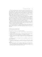
EMS is the item that consists of the basic details on the engine configuration and controls. The most
important aspect in diagnosing malfunction is to figure out how to analyze the components that are
not visible. To do this, you will learn the following 4 main points.
Understand the overall circuit of the EMS configuration: You can see the entire configuration and
PCM control at a single glance.
Check Input/Output terminal information: Check the input/output information of each component
and understand what signal the components transmit and receive.
Analyze service data: You must be able to analyze the invisible data exchange through the output
readings of the sensors.
Check DTC: You must know what items are included in the component related error codes.
Diagnosis of Gasoline Engine System
7
Error! Use the Home tab to apply 제목 1 to the text that you want to appear here. Error! Use the Home tab to
apply 제목 1 to the text that you want to appear here.
8
Diagnosis of Gasoline Engine System
Diagnosis of Gasoline Engine System
Diagnosis of Gasoline Engine System
Error! Use the Home tab to apply 제목 1 to the text that you want to
1.1
Basic Knowledge of the System
1.1.1
System Overview
Demands have increased for improvement of related technology including safety, convenience,
economy and environmental protection of vehicle. In the past, engine control has been achieved
through mechanical elements such as carburetor or power distributor.
However, simultaneous control of exhaust gas was impossible and optimal control of engine was
difficult.
was developed by Bosch.
mechanical fuel control system, injector was
operated in simultaneous injection type, but recent engine uses independent injection type which
operates each injector independently.
System not only supplies required torque and output of engine and controls the air-fuel ratio for
exhaust gas control, but also controls the ignition timing. Recent EMS controls injectors, ETC, spark
plugs, etc. depending on the status vehicle and various sensors that measure mechanical values of
engine.
Diagnosis of Gasoline Engine System
9
Error! Use the Home tab to apply 제목 1 to the text that you want to appear here. Error! Use the Home tab to
apply 제목 1 to the text that you want to appear here.
1.1.2
Diagnosis of Gasoline Engine System
Roles
The figure shows the configuration of fuel injection control system, which consists of the intake system,
the fuel system and the control system. The intake system measures and controls the air required for
combustion of engine and consists of Mass Air Flow type and MAP sensor type depending on the
method of measuring the intake air. The fuel system supplies the fuel to the combustion chamber and
control system determines the optimal amount of fuel depending on the load and speed of the engine.
And, the amount of fuel supplied to the engine is controlled by injection time of injector.
(1) Intake System
The intake system has different methods of measuring intake air depending on the system. That is, there
is MAFS for direct measuring type. But for indirect measuring type, MAFS does not exist and MAP sensor
is installed at the intake manifold. In air flow diagram, air from the air duct passes through air cleaner
and flows into the combustion chamber via MAFS, throttle valve, surge tank, intake manifold and intake
port. What is important in this course is that the suction resistance of air should be low and that amount
of suction air should be measured accurately and fast.
(2) Control System
The control system receives input signals from various sensors of engine, calculates the optimal amount
of fuel injection in consideration of engine load status, rotation speed, driving performance of vehicle,
reduction of exhaust gas and reduction of fuel consumption rate, sends this data to injector and
controls the amount of fuel injection. Micro computer calculates the amount of basic fuel injection from
intake air flow and engine rpm, and calculates adjusted fuel amount by the input signal from various
sensors. In addition, it determines the injection timing and the cylinder to inject the fuel from CKP
sensor and CMP sensor, and controls the feedback by the signals from oxygen sensor.
10
Diagnosis of Gasoline Engine System
Diagnosis of Gasoline Engine System
1.1.3
Error! Use the Home tab to apply 제목 1 to the text that you want to
Input and Output Elements
Electronic control gasoline engine can be divided into input elements and output elements focusing on
ECU. The input element includes Air Mass Sensor (MAF) which measures the amounts of air flowing to
combustion chamber and transmits the value to ECU; Oxygen Sensor that informs the oxygen
concentration of exhaust gas discharged through exhaust pipe for control of air fuel ratio; and various
sensors that detect coolant temperature and rpm of engine so that ECU can control the engine normally.
The output element refers to the element that sends output signals directly from ECU to operate the
actuators or coils, and includes injector, ISA (Idle Speed Adjuster) and ignition coil. Such part that
controls these control elements is called 'Control System' and this control system can be largely divided
into ignition system, injector, idling speed controller and exhaust gas controller.
Diagnosis of Gasoline Engine System
11
Error! Use the Home tab to apply 제목 1 to the text that you want to appear here. Error! Use the Home tab to
apply 제목 1 to the text that you want to appear here.
1.1.4
Sensor
1.1.4.1
Temperature Sensor
[Coolant Temperature Sensor]
[Types of Temperature Sensor]
Diagnosis of Gasoline Engine System
[Oil Temperature Sensor ]
[Intake Temperature Sensor]
[Coolant Temperature Sensor Circuit]
First one is the sensor that detects the temperature, such as coolant temperature sensor, intake
temperature sensor and exhaust gas temperature sensor. It uses the property that resistance changes as
the temperature rises.
Its type includes NTC thermistor that has negative temperature coefficient, PTC thermistor that has
positive temperature coefficient and CTR thermistor where electric resistance rapidly changes over
some temperature.
(1) Sensors Applied to Vehicles
Coolant Temperature Sensor, Intake Temperature Sensor, Oil Temperature Sensor, Pin Thermo Sensor,
Exhaust Gas Temperature Sensor, Air Conditioner Indoor/Outdoor Temperature Sensor, LPG Temperature
Sensor
(2) Types of Thermistor
The sensor having a resistance that changes with an increase in temperature is called Thermistor
12
(-) Temperature Coefficient → NTC Thermistor (Negative Temperature Coefficient)
(+) Temperature Coefficient → PTC Thermistor (Positive Temperature Coefficient)
Electrical resistance rapidly changes at some temperature → CTR Thermistor (Critical Temperature
Resistor)
Diagnosis of Gasoline Engine System
Diagnosis of Gasoline Engine System
1.1.4.2
Error! Use the Home tab to apply 제목 1 to the text that you want to
Pressure Sensor
[Intake Manifold - MAP Sensor]
[Barometric Pressure Sensor in ECU]
Internal Structure of Pressure Sensor]
[MAP Sensor Circuit]
Sensors that detect the pressure include intake manifold pressure sensor and barometric pressure
sensor.
(1) MAP Sensor
MAP sensor is used to determine the basic injection of fuel, injection time and ignition time by indirectly
detecting the amount of intake air depending on the pressure change of intake manifold. MAP sensor is
installed at surge tank and measures the changes in absolute pressure in the intake manifold. When the
engine operates, the pressure in intake manifold changes depending on engine status. When the engine
load and rpm increase with throttle valve open, absolute pressure in intake manifold increases (decrease
in negative pressure). When the engine load and rpm decreases with throttle valve closed, absolute
pressure in the intake manifold decreases (increase in negative pressure). MAP sensor measures
absolute pressure in the intake manifold using the piezoelectric effects. It is connected to intake
manifold as vacuum port to detect the changes in pressure of intake manifold. The sensor consists of
piezo resistor that forms the bridge circuit and silicon chip. It has different resistance values for
deformation and the signals proportional to the pressure of intake manifold flow through the bridge
circuit.
(2) Barometric Pressure Sensor
Air pressure is an index that indicates the density of air. The air density gets lowered as the altitude gets
higher, resulting in less amount of air. Accordingly, the amount of fuel required to keep certain air-fuel
ratio decreases at the higher altitude. Likewise, it is required to adjust the ignition timing depending on
the density of air. It is used to compensate for adjustment of idling speed and operation of EGR valve in
some vehicles. Like this, air pressure should be measured to compensate for the changing density of air
over the altitude or climate and Barometric Pressure Sensor (BPS) is required for this. BPS is mounted as
all-in-one type with MAFS or installed inside engine ECU.
Diagnosis of Gasoline Engine System
13
Error! Use the Home tab to apply 제목 1 to the text that you want to appear here. Error! Use the Home tab to
apply 제목 1 to the text that you want to appear here.
1.1.4.3
Diagnosis of Gasoline Engine System
RPM Detection Sensor
[CKP Sensor]
[CMP Sensor]
[Magnetic Type - Analog]
[Hall-IC Type - Digital]
[Wheel Speed Sensor]
(1) CKPS
CranKshaft Position sensor (CKP) provides the reference signals such as fuel injection timing and ignition
timing by detecting the position of crank shaft and rpm of engine. There are several methods of
detecting the position of crank shaft. Commonly used methods include electronic induction type that
uses Magnetic Pick-up and Tone Wheel, and optical type that consists of light emitting diodes (LED) and
photo diodes. Recently, hall effect type using Hall IC and Tone Wheel is used to display digital waveform.
Since CKP sensor is to detect the position of crank shaft while detecting rpm of engine, mount it so that
it faces the round shape tone wheel as shown in the above left figure. This tone wheel is installed inside
the cylinder block depending on the engine or installed together with fly wheel in the middle position
where it connects with transmission. Mounting position of CKP sensor differs depending on mounting
position of tone wheel. In most passenger cars, it is mounted on sides of cylinder block. In commercial
vehicles or some RV types, it is sometimes mounted at transmission housing.
In case of electronic induction type CKP sensor, several teeth are installed on tone wheel mounted on
crank shaft (the teeth differ depending on vehicle type and among 60 teeth installed at the interval of 6°
in general two teeth are deleted and used as reference points). Install the sensor close to the teeth. With
regard to output of electronic induction type CKP sensor, tone wheel installed on the crank shaft rotates
as the engine rotates. Accordingly, magnetic flux in the sensor changes and generates voltage signal. At
this time, the interval between the teeth and sensor is very important. If it is narrower than the specified
gap, it generates higher voltage than normal output signal to generate unstable state in fast driving
condition. If it is wider than the specified gap, it generates lower output voltage than the normal output
signal, generating problems at the time of cranking. Accordingly, it is very important to comply with
specified torque and gaps accurately when mounting CKP.
14
Diagnosis of Gasoline Engine System
Diagnosis of Gasoline Engine System
Error! Use the Home tab to apply 제목 1 to the text that you want to
(2) CMPS
Camshaft Position Sensor (CMP) is to monitor compression stroke TDC of No. 1 cylinder and is used to
identify each cylinder to determine the fuel injection and ignition sequence. Installation position of
sensor is the end of camshaft at all times to detect the position of camshaft. This sensor is called No.1
TDC sensor or face sensor (mode sensor) depending on the manufacturer, and the sensor that uses Hall
Effect is sometimes called hall sensor. Camshaft position sensor uses the principle of generating
electromotive force as the gap of the detection part of hall sensor changes while the teeth installed on
camshaft rotates together with camshaft. It generates 1 digital pulse signal for each rotation of camshaft
(2 rotations of crank shaft). That is, as the current flows in hall device, electron inside the device is biased
to one direction and the potential difference is generated so that this voltage is detected. Output
voltage is proportionate to the strength of current and magnetic field and it becomes bigger as the
device gets thinner.
(3) Vehicle Speed Sensor
Vehicle Speed Sensor (VSS) functions to inform to the engine ECU and instrument cluster whether the
vehicle is idling status or driving status. ECU controls idling speed control valve, canister purge valve,
torque converter, clutch, cruise control and speed sensitive auto door lock device of ETACS using this
signal. Vehicle speed sensor is available in reed switch type embedded in speedometer and the hall
sensor type using the hall effects installed at the transmission.
1.1.4.4
Operating Position Detection Sensor
[TPS Sensor]
[TPS Circuit]
[APS Sensor]
[Internal Structure of Sensor]
[APS Circuit]
(1) TPS
TPS is installed on the throttle body and detects the opening amount of throttle valve. ECU of engine
controls the fuel injection and ignition timing by determining the load status of engine with this output
voltage and is used as a signal that determines the idling status in some system. Output voltage of
variable resistance type potentiometer changes depending on the opening amount of throttle valve
and TPS plays a role of detecting the opening amount of throttle valve using this. Potentiometer is a
kind of variable resistor that is made up of lines of resistance or resistors. The figure shows the operation
example of TPS. Movement of throttle valve moves the vibrator of potentiometer and output voltage
Diagnosis of Gasoline Engine System
15
Error! Use the Home tab to apply 제목 1 to the text that you want to appear here. Error! Use the Home tab to
apply 제목 1 to the text that you want to appear here.
Diagnosis of Gasoline Engine System
comes from the signal terminal depending on the movement of vibrator. That is, it gives high voltage
(up to 5V) when throttle valve fully opens and low voltage (close to 0V) when it fully closes. When the
throttle valve is between them, it outputs the value between supply voltage and OV.
(2) APS
APS is the sensor applied to the vehicle mounted with ETC. Since acceleration pedal, throttle body and
wire are not mounted, ECU should recognize the position of acceleration pedal to control ETC. APS is
installed on the acceleration pedal to determine the acceleration will of driver. APS determines the
position of acceleration pedal using the potentiometer just like TPS. APS is very important signal for
safety of vehicle and has 2 output signals basically. Output of APS2 gives ½ value of APS1 output at all
times. APS1 signal is the main signal and if APS1 signal is defective, ECU determines the will of driver for
acceleration using APS2 signal. Recently, several types of vehicles are mounted with organ pedal for
better feeling of acceleration.
1.1.4.5
Oxygen Sensor
Oxygen sensor is mounted at exhaust gas manifold to detect the air-fuel ratio from the oxygen density
difference in the air and air density in exhaust gas. That is, when the output voltage is high (about 1V),
air-fuel ratio is concentrated, and if the output voltage is low (about 0V), air-fuel ratio is rare. In addition,
such change rapidly occurs around the theoretical air-fuel ratio. Accordingly, engine ECU controls the
fuel injection time to keep the fuel injection amount to theoretical air-fuel ratio by signal of oxygen
sensor.
As air pollution has emerged as a serious social problem, vehicle exhaust gas regulation has been
reinforced and automobile companies have developed various technologies to cope with such
regulation of exhaust gas. Among them, post-processing technology of exhaust gas using 3-way
catalytic converter is most widely used. 3-way catalytic converter is the device that purifies the harmful
exhaust gas using oxidation of HC, CO and reduction of Nox.
3-way catalytic converter has the highest purification rate around theoretical air-fuel ratio. If it is thicker
than theoretical air-fuel ratio, discharge of CO and HC increases and if it is rarer than theoretical air-fuel
ratio, discharge of Nox increases. Accordingly, it is required to control combustion at theoretical air-fuel
ratio for effective operation of 3-way catalytic converter. It is called control of air-
16
Diagnosis of Gasoline Engine System
Diagnosis of Gasoline Engine System
Error! Use the Home tab to apply 제목 1 to the text that you want to
control. In the control of air-fuel ratio, it is required to examine whether combustion occurs at
theoretical air-fuel ratio and the oxygen sensor performs this function.
There are 2 types of oxygen sensor depending on the devices used: zirconium oxide (ZrO2) type and
titanium oxide (TiO2) type. Zirconia oxygen sensor detects the changes of electromotive force by
difference in oxygen density in the air and the oxygen density in the exhaust gas. If the air-fuel ratio is
concentrated (if the density of oxygen in the exhaust gas is low), it generates high voltage close to
about 1V. If the air fuel ratio is rare (if the density of oxygen in the exhaust gas is high), it generates low
voltage close to about 0V, and rapidly changes around the theoretical air-fuel ratio. Titanium oxide
oxygen sensor detects the changes in resistance value depending on the difference in density of oxygen
and uses the property that resistance value rapidly changes around the theoretical air-fuel ratio.
1.1.4.6
Switch Types
Switches are one of input elements and include brake, clutch, air-conditioner, ignition and power
steering switches. Switch signal is sometimes installed at power or grounding line.
In addition, it is divided into pull-down type or pull-up type.
Brake Switch: Brake switch signal is the signal that determines the operation of brake pedal. For example,
when the brake switch signal is entered during cruise operation, it plays a role of releasing the cruise control.
Clutch Switch: Clutch switch is the signal that determines the operation of clutch and is used during
operation of cruise or at start-up.
Ignition Switch: When the ignition switch operates, power is supplied to all systems and components.
Inhibitor Switch: Inhibitor switch is the switch that detects the position of transmission lever and start-up is
possible only when P or N signal is entered to ECU. In addition, if D or R signal is entered to ECU in idle status,
ECU increases idle rpm and compensates for the load of engine.
Power Steering Switch: Power steering pump is the device operated by engine power and idle rpm becomes
unstable when the power steering pump operates at the engine idle. To compensate for this, when power
steering pump operates, switch On signal is entered to ECU. Then ECU increases engine rpm to stabilize idle
rpm. Recently, several types of vehicles complement steering using electric motors such as MDPS and EHPS.
In these vehicles, power steering switch is removed.
A/C Switch: When the driver operates the air conditioner, engine idle rpm becomes unstable. To compensate
for this, ECU increases engine idle rpm when the switch signal is entered.
Diagnosis of Gasoline Engine System
17
Error! Use the Home tab to apply 제목 1 to the text that you want to appear here. Error! Use the Home tab to
apply 제목 1 to the text that you want to appear here.
1.1.4.7
Diagnosis of Gasoline Engine System
Others
[Acceleration Sensor ]
[Battery Voltage]
[Immobilizer Input]
[Battery Sensor]
[Communication Signal]
[FR Terminal Signal]
[Self-Diagnosis Connector-DLC]
(1) Acceleration Sensor
When the vehicle drives on the unpaved road, the vehicle speed rapidly changes due to unstable
behavior of vehicle. ECU may recognize this situation as a misfire. To prevent this, acceleration sensor is
installed inside the engine room to determine whether misfire actually occurs. Since the wheel speed
sensor can determine the status of road if ABS is installed at the vehicle, separate acceleration sensor is
not required. Even if the vehicle is without ABS, separate wheel speed sensor is installed at the front
passenger side for recent vehicles so that road condition can be identified.
(2) Communication Signal
Vehicles share information with other systems through communication. For example, for vehicle speed
signal, ECU receives vehicle speed information through communication line from ABS module. In
addition, TCU requests ECU to reduce torque and this signal is entered to EUC through communication
line.
(3) FR Terminal Signal
This signal is used to detect the load caused by operation of alternator. If operation load of alternator is
big (for operation of heating wire), ECU increases rpm of engine to stabilize idle rpm of engine.
(4) Battery Sensor
Through battery sensor, ECU determines the status of battery. Battery sensor detects voltage, current
and temperature of battery and delivers the data to ECU through LIN communication line.
18
Diagnosis of Gasoline Engine System
Diagnosis of Gasoline Engine System
1.1.5
Actuator
1.1.5.1
Motor (H-Bridge)
Error! Use the Home tab to apply 제목 1 to the text that you want to
[ETC]
[Clockwise ]
[Counterclockwise ]
[Hold]
Motor control using H bridge includes ETC (Electric Throttle Control) and MTC (Manifold Throttle Valve).
Above figure is Delphi type H-bridge motor operation circuit and the circuit is configured using 4
transistors. When TR1 and TR4 operate in the circuit, IG power applies power to the motor via TR1 and
connects to the ground via TR4 so that the motor rotates clockwise.
It is required to change the polarity at both ends of motor in order to change rotation direction at the
DC motor. When TR2 and TR3 operate at the H bridge interface circuit, polarity changes at both ends of
the motor so that the motor rotates counterclockwise. Motor has rotational inertia so that it rotates even
if power is cut off. Since it is a throttle valve that controls the amounts of intake air, precision of control is
required ECU controls the throttle valve to the set track using the motor. It controls the brake at the
motor and keeps the setting position.
Brake control of DC motor stops when the closed circuit is configured based on the motor. Whether it is
plus or minus, when the same polarity is approved to both ends of motor, the motor immediately stops.
Diagnosis of Gasoline Engine System
19
Error! Use the Home tab to apply 제목 1 to the text that you want to appear here. Error! Use the Home tab to
apply 제목 1 to the text that you want to appear here.
1.2
Worksheet
1.2.1
PCM (ECM) Circuit Analysis
Lesson
Objective
Vehicle/Lesson
Materials
Diagnosis of Gasoline Engine System
Understand the overall configuration and know the operation flow of the Input/Output
components of the ECM through PCM circuit analysis.
Worksheet (course material), highlighter (red, blue, yellow)
Hands-ontraining time
30 min.
Mark the items that pertain to ① the battery power input, ② sensor input and ③ actuator output
on the PCM circuit with a highlighter.
① Battery Power Input (Red)
Battery, ECU FUSE-1, 3 and 4, Engine Control Relay, Sensor Fuse, Power
Connection Terminal 1 2 3
② Sensor Input (Yellow)
Rail Pressure Sensor, Fuel Tank Pressure Sensor, APT sensor, MAP Sensor,
Oxygen Sensor, Battery Sensor, FF Sensor, CKP/CMP Sensor, Knock Sensor,
Water Temperature Sensor, APS, TPS
③ Actuator Output (Blue)
Injector, Purge Control Solenoid Valve, Fuel Pressure Regulator Valve, Oil
Control Valve, Canister Close Valve, Variable Intake Valve, Fuel Sensor & Pump,
Ignition Coil, ETC Motor
[Example]
20
Diagnosis of Gasoline Engine System
Diagnosis of Gasoline Engine System
1.2.2
Error! Use the Home tab to apply 제목 1 to the text that you want to
Data Analysis
Check the following essential factors for troubleshooting the EMS input/output
components through hands-on practice and organize the results.
Lesson
Objective
Understand configuration circuit (check terminal signal reading)
Understand the DTC items and detection conditions.
Measure and analyze service data
Vehicle/Lesson
Materials
6 GDSs
GDI Engine
GDI Engine
Hands-ontraining time
120 min.
Complete the following tasks on PCM input/output items.
Input/Output Items
Power Input
(1) Engine control relay
(2) Battery power
(3) MAP sensor
(4) Oxygen sensor
(5) Throttle position sensor
(6) Crankshaft position sensor
Sensor Signals Input
(7) Camshaft position sensor
(8) ETC motor
Actuator Output
(9) Ignition coil
(10) Injector
Task
① Complete the circuit
Complete the given circuit.
② Organize DTCs
Find the DTC that corresponds to the presented
condition.
③ Measure service data
Measure and record the relevant service data.
④ Check symptoms when disconnected
Check DTC and symptoms in case of disconnection.
Diagnosis of Gasoline Engine System
21
Error! Use the Home tab to apply 제목 1 to the text that you want to appear here. Error! Use the Home tab to
apply 제목 1 to the text that you want to appear here.
22
Diagnosis of Gasoline Engine System
Diagnosis of Gasoline Engine System
Error! Use the Home tab to apply 제목 1 to the text that you want to
Diagnosis of Gasoline Engine System
1.2.2.1
Power Input & Engine Control Relay
(1) Component information and relevant circuit
Complete the missing part of the circuit diagram and fill in the functions for each terminal in the PCM
blank space.
(2) Terminal Information
Check signal value for each terminal.
Terminal
Signal Name
Condition
Signal Value
IG ON
12V
Hot at all time
12V
Battery Power (ON/START)
IG ON
12V
Engine Control Relay
Control
IG ON
0V
3, 5, 6
Engine Control Relay
75, 58
Battery Power (B+)
41
53
Diagnosis of Gasoline Engine System
IG OFF
12V
IG OFF
12V
23
Error! Use the Home tab to apply 제목 1 to the text that you want to appear here. Error! Use the Home tab to
apply 제목 1 to the text that you want to appear here.
Diagnosis of Gasoline Engine System
(3) DTC (Error Code)
Find the DTC items relevant to the PCM Power Input and fill in the blanks.
DTC
Name
Condition
In case the main relay rear end voltage is lower
than 6V after KEY ON
In case the main relay rear end voltage is higher
System Voltage
than 6V after KEY OFF
In case the comparison result between the main
relay rear end voltage and IG Key rear end voltage
is higher than 3.8 - 8.45V.
System Voltage Low
In case the battery voltage fed from the main relay is
lower than (______________)V.
System Voltage High
In case the battery voltage fed from the main relay is
higher than 16V.
(4) Service Data
Measure and record the service data from the following items.
Item
IG ON
Battery Voltage
12.1V
Ignition Voltage (IG ON)
Ignition Switch
NO
Main Relay
Quiz !
What are the operating devices that are affected by the main relay (engine control relay)?
24
Diagnosis of Gasoline Engine System
Error! Use the Home tab to apply 제목 1 to the text that you want to
Diagnosis of Gasoline Engine System
1.2.2.2
MAP Sensor
(1) Component information and relevant circuit
Complete the missing part of the circuit diagram and fill in the functions for each terminal in the PCM
blank space.
(2) Terminal Information
Check signal value for each terminal.
Terminal
Signal Name
59
Air Intake Temperature Sensor Signal Input
61
Air Intake Temperature Sensor Ground
82
MAP Sensor Signal Input
103
MAP Sensor Power
Diagnosis of Gasoline Engine System
Condition
Signal Value
Idle
2.55V
-
0V
Idle
0.8~1.6V
IG ON
5V
25