- Trang chủ >>
- Khoa Học Tự Nhiên >>
- Vật lý
x ray adsorption spectroscopy of semiconductores
Bạn đang xem bản rút gọn của tài liệu. Xem và tải ngay bản đầy đủ của tài liệu tại đây (16.69 MB, 367 trang )
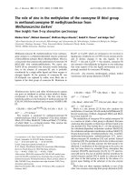
Springer Series in Optical Sciences 190
Claudia S. Schnohr
Mark C. Ridgway Editors
X-Ray Absorption
Spectroscopy of
Semiconductors
Springer Series in Optical Sciences
Volume 190
Founded by
H.K.V. Lotsch
Editor-in-Chief
William T. Rhodes, Georgia Institute of Technology, Atlanta, USA
Editorial Board
Ali Adibi, Georgia Institute of Technology, Atlanta, USA
Toshimitsu Asakura, Hokkai-Gakuen University, Sapporo, Japan
Theodor W. Hänsch, Max-Planck-Institut für Quantenoptik, Garching, Germany
Ferenc Krausz, Ludwig-Maximilians-Universität München, Garching, Germany
Bo A.J. Monemar, Linköping University, Linköping, Sweden
Herbert Venghaus, Fraunhofer Institut für Nachrichtentechnik, Berlin, Germany
Horst Weber, Technische Universität Berlin, Berlin, Germany
Harald Weinfurter, Ludwig-Maximilians-Universität München, München, Germany
www.pdfgrip.com
Springer Series in Optical Sciences
The Springer Series in Optical Sciences, under the leadership of Editor-in-Chief William T. Rhodes,
Georgia Institute of Technology, USA, provides an expanding selection of research monographs in all
major areas of optics: lasers and quantum optics, ultrafast phenomena, optical spectroscopy techniques,
optoelectronics, quantum information, information optics, applied laser technology, industrial applications, and other topics of contemporary interest.
With this broad coverage of topics, the series is of use to all research scientists and engineers who need
up-to-date reference books.
The editors encourage prospective authors to correspond with them in advance of submitting a manuscript. Submission of manuscripts should be made to the Editor-in-Chief or one of the Editors. See also
www.springer.com/series/624
Editor-in-Chief
William T. Rhodes
School of Electrical and Computer Engineering
Georgia Institute of Technology
Atlanta, GA 30332-0250
USA
e-mail:
Editorial Board
Ali Adibi
School of Electrical and Computer Engineering
Georgia Institute of Technology
Atlanta, GA 30332-0250
USA
e-mail:
Toshimitsu Asakura
Faculty of Engineering
Hokkai-Gakuen University
1-1, Minami-26, Nishi 11, Chuo-ku
Sapporo, Hokkaido 064-0926, Japan
e-mail:
Bo A.J. Monemar
Department of Physics and Measurement
Technology
Materials Science Division
Linköping University
58183 Linköping, Sweden
e-mail:
Herbert Venghaus
Fraunhofer Institut für Nachrichtentechnik
Heinrich-Hertz-Institut
Einsteinufer 37
10587 Berlin, Germany
e-mail:
Theodor W. Hänsch
Max-Planck-Institut für Quantenoptik
Hans-Kopfermann-Straße 1
85748 Garching, Germany
e-mail:
Ferenc Krausz
Ludwig-Maximilians-Universität München
Lehrstuhl für Experimentelle Physik
Am Coulombwall 1
85748 Garching, Germany and
Max-Planck-Institut für Quantenoptik
Hans-Kopfermann-Straße 1
85748 Garching, Germany
e-mail:
Horst Weber
Optisches Institut
Technische Universität Berlin
Straße des 17. Juni 135
10623 Berlin, Germany
e-mail:
Harald Weinfurter
Sektion Physik
Ludwig-Maximilians-Universität München
Schellingstraße 4/III
80799 München, Germany
e-mail:
More information about this series at />
www.pdfgrip.com
Claudia S. Schnohr Mark C. Ridgway
•
Editors
X-Ray Absorption
Spectroscopy of
Semiconductors
123
www.pdfgrip.com
Editors
Claudia S. Schnohr
Institut für Festkörperphysik
Friedrich-Schiller-Universität Jena
Jena
Germany
ISSN 0342-4111
ISBN 978-3-662-44361-3
DOI 10.1007/978-3-662-44362-0
Mark C. Ridgway
Department of Electronic Materials
Engineering
Australian National University
Canberra, ACT
Australia
ISSN 1556-1534 (electronic)
ISBN 978-3-662-44362-0 (eBook)
Library of Congress Control Number: 2014951156
Springer Heidelberg New York Dordrecht London
© Springer-Verlag Berlin Heidelberg 2015
This work is subject to copyright. All rights are reserved by the Publisher, whether the whole or part of
the material is concerned, specifically the rights of translation, reprinting, reuse of illustrations,
recitation, broadcasting, reproduction on microfilms or in any other physical way, and transmission or
information storage and retrieval, electronic adaptation, computer software, or by similar or dissimilar
methodology now known or hereafter developed. Exempted from this legal reservation are brief
excerpts in connection with reviews or scholarly analysis or material supplied specifically for the
purpose of being entered and executed on a computer system, for exclusive use by the purchaser of the
work. Duplication of this publication or parts thereof is permitted only under the provisions of
the Copyright Law of the Publisher’s location, in its current version, and permission for use must always
be obtained from Springer. Permissions for use may be obtained through RightsLink at the Copyright
Clearance Center. Violations are liable to prosecution under the respective Copyright Law.
The use of general descriptive names, registered names, trademarks, service marks, etc. in this
publication does not imply, even in the absence of a specific statement, that such names are exempt
from the relevant protective laws and regulations and therefore free for general use.
While the advice and information in this book are believed to be true and accurate at the date of
publication, neither the authors nor the editors nor the publisher can accept any legal responsibility for
any errors or omissions that may be made. The publisher makes no warranty, express or implied, with
respect to the material contained herein.
Printed on acid-free paper
Springer is part of Springer Science+Business Media (www.springer.com)
www.pdfgrip.com
Preface
X-ray Absorption Spectroscopy (XAS) is a powerful technique with which to probe
the properties of matter, equally applicable to the solid, liquid and gas phases. Its
unique characteristics, including element-specificity and nanometer range, make it a
versatile probe that provides structural information distinctly different and complementary to that obtained by other common techniques such as X-ray diffraction
or electron microscopy. Since the pioneering works in the early 1970s, XAS has
progressed tremendously with respect to both experimental techniques and theoretical understanding. Modern synchrotron lightsources not only enable standard
XAS measurements with extremely high data quality, they also facilitate studies on
the subsecond or nanometer scale. This provides a large variety of new applications
such as time-resolved measurements of dynamic processes or structural characterization of single nanostructures. The theoretical understanding of XAS has progressed at a similar pace and several computer codes capable of calculating the
X-ray absorption fine structure to within the experimental uncertainty are now
readily available. It therefore seems a mere consequence that XAS is these days
widely used in a large number of fields including physics, chemistry, material
science, geology, biology and environmental science.
Semiconductors form the basis of an ever-growing variety of electronic and
photonic devices that permeate almost every aspect of today’s society. From mobile
phones to cars, from washing machines to artificial light, semiconductor technology
is at the bottom of nearly all modern appliances. Advanced telecommunications, the
key to a global world, is utterly unthinkable without the achievements made in the
semiconductor industry over the last decades. These developments, however, are far
from completed. Currently, the whole new world of nanomaterials is being explored
extensively and first concepts to utilize the unique properties thus discovered are
being implemented. Semiconductor materials also play a vital role in the quest for a
sustainable energy supply, one of the big global challenges of the twenty-first
century. By directly converting sunlight to electricity, photovoltaic devices such as
solar cells provide a versatile and renewable energy source. The growing and
changing demands of future technology in nearly all aspects of modern life therefore
continuously require improving current and developing new semiconductor devices.
v
www.pdfgrip.com
vi
Preface
The most effective utilization of these materials, today and tomorrow, necessitates a detailed knowledge of their structural properties as they determine other
electrical, optical or magnetic properties crucial for device performance. XAS has
provided unique and valuable insight into these relations for a large number of
semiconductor systems. It is therefore the aim of this book to present a comprehensive overview of past and present research activities in this ever growing field.
Chapter 1 is dedicated to a short introduction to XAS and is aimed primarily at
newcomers to the technique. It presents all the basic information necessary to
follow the subsequent chapters and provides references for further reading. The
following chapters are dedicated to XAS research of distinct groups of materials.
Part I comprises Chaps. 2–6 and is dedicated to crystalline semiconductors spanning topics such as alloying, wide band gap materials, dopants and clusters and
vibrational properties. Part II presents research on disordered semiconductors with
amorphous materials covered in Chaps. 7 and 8 while phase changes due to extreme
conditions such as high temperature and high pressure are discussed in Chap. 9.
Part III consists of Chaps. 10–13 and is dedicated to semiconductor nanostructures
such as quantum dots, nanoparticles and nanowires of various group IV, III–V and
II–VI materials. The last section, Part IV, concerns the investigation of magnetic
ions such as Mn, Co and Fe incorporated in different group IV, III–V and II–VI
semiconductors discussed in Chaps. 14–16, respectively.
Each chapter summarizes the research activities of the respective field and
highlights important experimental results thus demonstrating the capabilities and
applications of the XAS technique. As such, this book provides a comprehensive
review and valuable reference guide for both XAS newcomers and experts involved
in semiconductor materials research.
Jena, Canberra
Claudia S. Schnohr
Mark C. Ridgway
www.pdfgrip.com
Contents
1
Introduction to X-Ray Absorption Spectroscopy
Claudia S. Schnohr and Mark C. Ridgway
1.1 Basic Principle . . . . . . . . . . . . . . . . . . . . .
1.1.1 X-Ray Absorption . . . . . . . . . . . . . .
1.1.2 Absorption Fine Structure. . . . . . . . .
1.2 Theoretical Description . . . . . . . . . . . . . . . .
1.2.1 Dipole Approximation . . . . . . . . . . .
1.2.2 Quasi-Particle Model . . . . . . . . . . . .
1.2.3 Multiple Scattering Approach . . . . . .
1.2.4 XANES . . . . . . . . . . . . . . . . . . . . .
1.2.5 EXAFS . . . . . . . . . . . . . . . . . . . . .
1.3 Experimental Aspects . . . . . . . . . . . . . . . . .
1.3.1 Synchrotron Radiation . . . . . . . . . . .
1.3.2 Experimental Setup . . . . . . . . . . . . .
1.4 Data Analysis . . . . . . . . . . . . . . . . . . . . . .
1.4.1 XANES . . . . . . . . . . . . . . . . . . . . .
1.4.2 EXAFS . . . . . . . . . . . . . . . . . . . . .
1.5 Conclusions . . . . . . . . . . . . . . . . . . . . . . .
References . . . . . . . . . . . . . . . . . . . . . . . . . . . .
Part I
2
.............
.
.
.
.
.
.
.
.
.
.
.
.
.
.
.
.
.
.
.
.
.
.
.
.
.
.
.
.
.
.
.
.
.
.
.
.
.
.
.
.
.
.
.
.
.
.
.
.
.
.
.
.
.
.
.
.
.
.
.
.
.
.
.
.
.
.
.
.
.
.
.
.
.
.
.
.
.
.
.
.
.
.
.
.
.
.
.
.
.
.
.
.
.
.
.
.
.
.
.
.
.
.
.
.
.
.
.
.
.
.
.
.
.
.
.
.
.
.
.
.
.
.
.
.
.
.
.
.
.
.
.
.
.
.
.
.
.
.
.
.
.
.
.
.
.
.
.
.
.
.
.
.
.
.
.
.
.
.
.
.
.
.
.
.
.
.
.
.
.
.
.
.
.
.
.
.
.
.
.
.
.
.
.
.
.
.
.
.
.
.
.
.
.
.
.
.
.
.
.
.
.
.
.
.
1
.
.
.
.
.
.
.
.
.
.
.
.
.
.
.
.
.
1
1
2
4
4
5
6
7
8
12
12
13
17
17
20
26
26
.....................
29
.
.
.
.
.
.
29
31
31
32
33
33
Crystalline Semiconductors
Binary and Ternary Random Alloys .
Claudia S. Schnohr
2.1 Introduction . . . . . . . . . . . . . . .
2.2 Si1Àx Gex Binary Alloys . . . . . . .
2.2.1 First Shell . . . . . . . . . . .
2.2.2 Higher Shells . . . . . . . . .
2.3 III–V and II–VI Ternary Alloys . .
2.3.1 First Shell . . . . . . . . . . .
.
.
.
.
.
.
.
.
.
.
.
.
.
.
.
.
.
.
.
.
.
.
.
.
.
.
.
.
.
.
.
.
.
.
.
.
.
.
.
.
.
.
.
.
.
.
.
.
.
.
.
.
.
.
.
.
.
.
.
.
.
.
.
.
.
.
.
.
.
.
.
.
.
.
.
.
.
.
.
.
.
.
.
.
.
.
.
.
.
.
.
.
.
.
.
.
.
.
.
.
.
.
.
.
.
.
.
.
.
.
.
.
.
.
.
.
.
.
.
.
vii
www.pdfgrip.com
viii
Contents
2.3.2 Higher Shells . . . . . . . . . . . . . . . . . . . . . .
2.3.3 Bond Angles. . . . . . . . . . . . . . . . . . . . . . .
2.4 First Shell Calculations . . . . . . . . . . . . . . . . . . . . .
2.4.1 Models for the Dilute Limit . . . . . . . . . . . .
2.4.2 Models for the Whole Compositional Range .
2.4.3 Cluster and Supercell Calculations . . . . . . . .
2.4.4 Comparison of the Different Models . . . . . .
2.5 Modelling of Higher Shells . . . . . . . . . . . . . . . . . .
2.6 Conclusions . . . . . . . . . . . . . . . . . . . . . . . . . . . .
References . . . . . . . . . . . . . . . . . . . . . . . . . . . . . . . . .
3
4
Wide Band Gap Materials . . . . . . . . . . . . . . . . . .
Maria Katsikini
3.1 Introduction . . . . . . . . . . . . . . . . . . . . . . . . .
3.2 XANES Characterization . . . . . . . . . . . . . . . .
3.2.1 Polarization Dependent Measurements . .
3.2.2 Polymorphism and Multiphase Materials
3.2.3 Core Exciton in Diamond . . . . . . . . . .
3.2.4 Ion Implantation and Defects . . . . . . . .
3.2.5 Near Edge Spectra Simulations . . . . . .
3.3 EXAFS Characterization . . . . . . . . . . . . . . . .
3.3.1 Binary Compounds . . . . . . . . . . . . . . .
3.3.2 Effect of Temperature . . . . . . . . . . . . .
3.3.3 Alloying. . . . . . . . . . . . . . . . . . . . . . .
3.3.4 Ion Implantation . . . . . . . . . . . . . . . . .
3.3.5 Effect of Pressure . . . . . . . . . . . . . . . .
3.4 Summary . . . . . . . . . . . . . . . . . . . . . . . . . . .
References . . . . . . . . . . . . . . . . . . . . . . . . . . . . . .
.
.
.
.
.
.
.
.
.
.
35
38
38
38
39
42
42
43
45
46
...........
49
.
.
.
.
.
.
.
.
.
.
.
.
.
.
.
.
.
.
.
.
.
.
.
.
.
.
.
.
.
.
49
54
54
59
62
63
66
68
68
69
70
71
72
74
74
.........
77
.
.
.
.
.
.
.
.
.
.
.
.
77
77
78
83
83
84
86
89
90
92
94
95
.
.
.
.
.
.
.
.
.
.
.
.
.
.
.
Dopants . . . . . . . . . . . . . . . . . . . . . . . . . . . . . . . . . .
Federico Boscherini
4.1 Introduction to X-Ray Absorption Fine Structure
Investigations of Dopants . . . . . . . . . . . . . . . . . .
4.1.1 General Aspects . . . . . . . . . . . . . . . . . . .
4.1.2 Experimental Methods . . . . . . . . . . . . . . .
4.2 A Review of XAFS Investigations of Dopants. . . .
4.2.1 Amorphous Semiconductors . . . . . . . . . . .
4.2.2 Crystalline Silicon: Bulk . . . . . . . . . . . . .
4.2.3 Crystalline Silicon: Ultra Shallow Junctions
4.2.4 Solar Grade Silicon . . . . . . . . . . . . . . . . .
4.2.5 Gallium Arsenide . . . . . . . . . . . . . . . . . .
4.2.6 Zinc Oxide . . . . . . . . . . . . . . . . . . . . . . .
4.2.7 Other Semiconductors . . . . . . . . . . . . . . .
References . . . . . . . . . . . . . . . . . . . . . . . . . . . . . . . .
www.pdfgrip.com
.
.
.
.
.
.
.
.
.
.
.
.
.
.
.
.
.
.
.
.
.
.
.
.
.
.
.
.
.
.
.
.
.
.
.
.
.
.
.
.
.
.
.
.
.
.
.
.
.
.
.
.
.
.
.
.
.
.
.
.
.
.
.
.
.
.
.
.
.
.
.
.
.
.
.
.
.
.
.
.
.
.
.
.
.
.
.
.
.
.
.
.
.
.
.
.
.
.
.
.
.
.
.
.
.
.
.
.
.
.
.
.
.
.
.
.
.
.
.
.
.
.
.
.
.
.
.
.
.
.
.
.
.
.
.
.
.
.
.
.
.
.
.
.
.
.
.
.
.
.
.
.
.
.
.
.
.
.
.
.
.
.
.
.
.
.
.
.
.
.
.
.
.
.
.
.
.
.
.
.
.
.
.
.
.
.
.
.
.
.
.
.
.
.
.
.
.
.
.
.
.
.
.
.
.
.
.
.
.
.
.
.
.
.
.
.
.
.
.
.
.
.
.
.
.
.
.
.
.
.
.
.
.
.
.
.
.
.
.
.
.
.
.
.
.
.
.
.
.
.
.
.
.
.
.
.
.
.
.
.
.
.
.
.
.
.
.
.
.
.
.
.
.
.
.
.
.
.
.
.
.
.
.
.
.
.
Contents
5
6
Complexes and Clusters . . . . . . . . . . . . . . . . . . . . . . . . . . . .
Gianluca Ciatto
5.1 Definition of Complexes and Clusters. . . . . . . . . . . . . . . .
5.2 Modeling and Data Analysis Approaches . . . . . . . . . . . . .
5.2.1 Conventional XAS Analysis of Complexes/Clusters .
5.2.2 Valence Force Field-Based XAS Analysis
of Complexes/Clusters . . . . . . . . . . . . . . . . . . . . .
5.2.3 Density Functional Theory-Based Analysis
of Complexes/Clusters . . . . . . . . . . . . . . . . . . . . .
5.3 Complexes . . . . . . . . . . . . . . . . . . . . . . . . . . . . . . . . . .
5.3.1 Nitrogen–Hydrogen Complexes in Dilute Nitrides . .
5.3.2 Manganese–Hydrogen Complexes in GaMnAs . . . .
5.3.3 Cobalt–Oxygen Vacancy Complexes in Zn1Àx Cox O.
5.3.4 Erbium at Oxygen-Decorated Vacancies
in (Er, O)-Doped Silicon . . . . . . . . . . . . . . . . . . .
5.4 Clustering and Anticlustering. . . . . . . . . . . . . . . . . . . . . .
5.4.1 Bismuth Clustering in GaAsBi Epilayers . . . . . . . .
5.4.2 Absence of Clustering in GaAsSbN and ZnSSe. . . .
5.5 Summary . . . . . . . . . . . . . . . . . . . . . . . . . . . . . . . . . . .
References . . . . . . . . . . . . . . . . . . . . . . . . . . . . . . . . . . . . . .
...
99
...
...
...
99
100
100
...
101
.
.
.
.
.
.
.
.
.
.
.
.
.
.
.
102
103
103
107
111
.
.
.
.
.
.
.
.
.
.
.
.
.
.
.
.
.
.
115
117
118
121
122
123
....
127
.
.
.
.
.
.
.
.
.
.
.
.
.
.
.
.
.
.
.
.
.
.
.
.
127
128
129
130
131
132
133
133
135
139
139
141
................
145
................
................
................
145
146
147
Vibrational Anisotropy . . . . . . . . . . . . . . . . . . . . . . . . . . . .
Paolo Fornasini
6.1 Introduction . . . . . . . . . . . . . . . . . . . . . . . . . . . . . . . .
6.2 Theory . . . . . . . . . . . . . . . . . . . . . . . . . . . . . . . . . . . .
6.2.1 Average Distance . . . . . . . . . . . . . . . . . . . . . . .
6.2.2 Parallel MSRD . . . . . . . . . . . . . . . . . . . . . . . . .
6.2.3 Perpendicular MSRD . . . . . . . . . . . . . . . . . . . . .
6.2.4 Relative Vibrational Anisotropy . . . . . . . . . . . . .
6.3 Experimental Results on Vibrational Anisotropy . . . . . . .
6.3.1 The Case of CdTe . . . . . . . . . . . . . . . . . . . . . . .
6.3.2 Comparison of Diamond and Zinblende Structures
6.4 True and Apparent Bond Expansion . . . . . . . . . . . . . . . .
6.5 Negative Thermal Expansion Crystals. . . . . . . . . . . . . . .
References . . . . . . . . . . . . . . . . . . . . . . . . . . . . . . . . . . . . .
Part II
7
ix
.
.
.
.
.
.
.
.
.
.
.
.
.
.
.
.
.
.
.
.
.
.
.
.
Disordered Semiconductors
Amorphous Group IV Semiconductors . . . .
Mark C. Ridgway
7.1 Introduction . . . . . . . . . . . . . . . . . . . .
7.2 Structure of Amorphous Semiconductors.
7.3 XAS of Amorphous Semiconductors . . .
www.pdfgrip.com
x
Contents
7.4
Preparation of Amorphous Group IV Semiconductor
Samples for XAS. . . . . . . . . . . . . . . . . . . . . . . . .
7.5 Amorphous Group IV Semiconductors . . . . . . . . . .
7.5.1 Amorphous Si (a-Si) . . . . . . . . . . . . . . . . .
7.5.2 Amorphous Ge (a-Ge) . . . . . . . . . . . . . . . .
7.5.3 Amorphous SiC (a-SiC) . . . . . . . . . . . . . . .
7.5.4 Amorphous Si1Àx Gex (a-Si1Àx Gex Þ. . . . . . . .
7.6 Summary . . . . . . . . . . . . . . . . . . . . . . . . . . . . . .
References . . . . . . . . . . . . . . . . . . . . . . . . . . . . . . . . .
8
9
.
.
.
.
.
.
.
.
.
.
.
.
.
.
.
.
Amorphous Group III–V Semiconductors . . . . . . . . . . . .
Mark C. Ridgway
8.1 Introduction . . . . . . . . . . . . . . . . . . . . . . . . . . . . . .
8.2 Structure of Amorphous Group III–V Semiconductors .
8.3 Preparation of Amorphous Group III–V Semiconductor
Samples for XAS. . . . . . . . . . . . . . . . . . . . . . . . . . .
8.4 Amorphous Ga-Based Group III–V Semiconductors . . .
8.4.1 Amorphous GaN (a-GaN). . . . . . . . . . . . . . . .
8.4.2 Amorphous GaP (a-GaP) . . . . . . . . . . . . . . . .
8.4.3 Amorphous GaAs (a-GaAs) . . . . . . . . . . . . . .
8.4.4 Amorphous GaSb (a-GaSb) . . . . . . . . . . . . . .
8.5 Amorphous In-Based Group III–V Semiconductors . . .
8.5.1 Amorphous InN (a-InN) . . . . . . . . . . . . . . . . .
8.5.2 Amorphous InP (a-InP) . . . . . . . . . . . . . . . . .
8.5.3 Amorphous InAs (a-InAs) . . . . . . . . . . . . . . .
8.5.4 Amorphous InSb (a-InSb). . . . . . . . . . . . . . . .
8.6 Summary . . . . . . . . . . . . . . . . . . . . . . . . . . . . . . . .
References . . . . . . . . . . . . . . . . . . . . . . . . . . . . . . . . . . .
Semiconductors Under Extreme Conditions . . . . . . . . . . .
Andrea Di Cicco and Adriano Filipponi
9.1 Introduction . . . . . . . . . . . . . . . . . . . . . . . . . . . . . .
9.2 Experimental Set-Ups at Scanning Energy Beamlines . .
9.3 Experimental Set-Ups at Energy-Dispersive Beamlines .
9.4 XAS of Amorphous and Liquid Se at High Pressures . .
9.5 The Physics of Ge and Related Systems at High
P and High T . . . . . . . . . . . . . . . . . . . . . . . . . . . . .
References . . . . . . . . . . . . . . . . . . . . . . . . . . . . . . . . . . .
www.pdfgrip.com
.
.
.
.
.
.
.
.
.
.
.
.
.
.
.
.
.
.
.
.
.
.
.
.
149
149
149
152
157
159
162
162
......
165
......
......
165
166
.
.
.
.
.
.
.
.
.
.
.
.
.
.
.
.
.
.
.
.
.
.
.
.
.
.
167
167
167
170
171
173
175
175
176
180
182
184
184
......
187
.
.
.
.
.
.
.
.
187
190
192
193
......
......
197
199
.
.
.
.
.
.
.
.
.
.
.
.
.
.
.
.
.
.
.
.
.
.
.
.
.
.
.
.
.
.
.
.
.
.
.
.
.
.
.
.
.
.
.
.
.
.
.
.
.
.
.
.
.
.
.
.
.
.
.
.
.
.
.
.
.
.
.
.
.
.
.
.
.
.
.
.
.
.
.
.
.
.
.
.
.
.
.
.
.
.
.
.
Contents
Part III
10
11
xi
Semiconductor Nanostructures
Group IV Quantum Dots and Nanoparticles . . . . . . . . . . . .
Alexander V. Kolobov
10.1 Introduction . . . . . . . . . . . . . . . . . . . . . . . . . . . . . . . .
10.2 Raman Scattering and Its Pitfalls . . . . . . . . . . . . . . . . . .
10.3 X-Ray Absorption Spectroscopy of Ge QDs
and Nanocrystals . . . . . . . . . . . . . . . . . . . . . . . . . . . . .
10.3.1 Epitaxially Grown Uncapped Ge QDs . . . . . . . . .
10.3.2 Capped Ge QDs . . . . . . . . . . . . . . . . . . . . . . . .
10.3.3 Ge Nanoislands Grown on Oxidised Si Surfaces . .
10.3.4 Embedded Ge Nanoparticles . . . . . . . . . . . . . . . .
10.3.5 Other-Than Ge Quantum Dots . . . . . . . . . . . . . .
10.4 Beyond Conventional XAFS . . . . . . . . . . . . . . . . . . . . .
10.4.1 Multiple Scattering Analysis of EXAFS . . . . . . . .
10.4.2 Diffraction Anomalous Fine Structure Experiments
10.4.3 Femtometer Precision XAFS. . . . . . . . . . . . . . . .
10.4.4 Spectroscopy of Empty States . . . . . . . . . . . . . . .
10.4.5 Time-Resolved Studies. . . . . . . . . . . . . . . . . . . .
10.5 Summary and Outlook . . . . . . . . . . . . . . . . . . . . . . . . .
References . . . . . . . . . . . . . . . . . . . . . . . . . . . . . . . . . . . . .
Group IV Nanowires . . . . . . . . . . . . . . . . . . . . . . . . . . . . .
Xuhui Sun and Tsun-Kong Sham
11.1 Introduction . . . . . . . . . . . . . . . . . . . . . . . . . . . . . . . .
11.2 Si and Ge Nanowires: Morphology and Structure
Via Top-down and Bottom up Strategies. . . . . . . . . . . . .
11.3 Soft X-Ray Spectroscopy: Yield Measurements, XANES,
XES and XEOL. . . . . . . . . . . . . . . . . . . . . . . . . . . . . .
11.3.1 X-Ray Absorption Fine Structure Spectroscopy . . .
11.3.2 Soft X-Ray Absorption Measurements: Yield
and De-excitation Spectroscopy. . . . . . . . . . . . . .
11.3.3 XEOL in the Time Domain . . . . . . . . . . . . . . . .
11.4 Si and Ge Nanowires and Related Materials: X-Ray
Spectroscopy Studies . . . . . . . . . . . . . . . . . . . . . . . . . .
11.4.1 Si Nanowires . . . . . . . . . . . . . . . . . . . . . . . . . .
11.4.2 Ge Nanowires and GeO2 Nanowires . . . . . . . . . .
11.4.3 Other Group IV Nanowires (C and SnO2
Nanowire) . . . . . . . . . . . . . . . . . . . . . . . . . . . .
11.5 Summary and Outlook . . . . . . . . . . . . . . . . . . . . . . . . .
References . . . . . . . . . . . . . . . . . . . . . . . . . . . . . . . . . . . . .
www.pdfgrip.com
....
203
....
....
203
204
.
.
.
.
.
.
.
.
.
.
.
.
.
.
.
.
.
.
.
.
.
.
.
.
.
.
.
.
207
208
211
215
217
218
218
218
219
219
219
220
220
220
....
223
....
223
....
224
....
....
225
225
....
....
226
229
....
....
....
230
230
236
....
....
....
241
242
244
.
.
.
.
.
.
.
.
.
.
.
.
.
.
.
.
.
.
.
.
.
.
.
.
.
.
.
.
xii
12
13
Contents
Group III–V and II–VI Quantum Dots and Nanoparticles .
Alexander A. Guda, Mikhail A. Soldatov
and Alexander V. Soldatov
12.1 Properties and Applications of Quantum Dots . . . . . . . .
12.2 Synthesis . . . . . . . . . . . . . . . . . . . . . . . . . . . . . . . . .
12.3 Methods to Study the QDs . . . . . . . . . . . . . . . . . . . . .
12.4 Case Studies . . . . . . . . . . . . . . . . . . . . . . . . . . . . . . .
12.4.1 Group III–V QDs and Nanoparticles . . . . . . . . .
12.4.2 Group II–VI QDs and Nanoparticles . . . . . . . . .
References . . . . . . . . . . . . . . . . . . . . . . . . . . . . . . . . . . . .
Group III–V and II–VI Nanowires .
Francesco d’Acapito
13.1 Introduction . . . . . . . . . . . . . .
13.2 III–V Wires. . . . . . . . . . . . . . .
13.2.1 GaAs and InAs . . . . . . .
13.2.2 GaN and AlGaN . . . . . .
13.3 II–VI Wires. . . . . . . . . . . . . . .
13.3.1 ZnO. . . . . . . . . . . . . . .
13.3.2 Other II–VI . . . . . . . . .
13.4 Conclusion . . . . . . . . . . . . . . .
References . . . . . . . . . . . . . . . . . . .
Part IV
14
15
.....
247
.
.
.
.
.
.
.
.
.
.
.
.
.
.
247
250
252
255
255
259
267
......................
269
.
.
.
.
.
.
.
.
.
.
.
.
.
.
.
.
.
.
269
270
270
271
274
274
281
284
284
............
289
.
.
.
.
.
.
.
.
.
.
.
.
.
.
.
.
.
.
289
290
293
295
297
297
303
309
310
........
313
........
........
313
314
........
319
.
.
.
.
.
.
.
.
.
.
.
.
.
.
.
.
.
.
.
.
.
.
.
.
.
.
.
.
.
.
.
.
.
.
.
.
.
.
.
.
.
.
.
.
.
.
.
.
.
.
.
.
.
.
.
.
.
.
.
.
.
.
.
.
.
.
.
.
.
.
.
.
.
.
.
.
.
.
.
.
.
.
.
.
.
.
.
.
.
.
.
.
.
.
.
.
.
.
.
.
.
.
.
.
.
.
.
.
.
.
.
.
.
.
.
.
.
.
.
.
.
.
.
.
.
.
.
.
.
.
.
.
.
.
.
.
.
.
.
.
.
.
.
.
.
.
.
.
.
.
.
.
.
.
.
.
.
.
.
.
.
.
.
.
.
.
.
.
.
.
.
.
.
.
.
.
.
.
.
.
.
.
.
.
.
.
.
.
.
.
.
.
.
.
.
.
.
.
.
.
.
Magnetic Semiconductors
Magnetic Ions in Group IV Semiconductors . . . .
Roberto Gunnella
14.1 Introduction . . . . . . . . . . . . . . . . . . . . . . . .
14.2 Theoretical Background . . . . . . . . . . . . . . . .
14.3 Experimental Growth Techniques. . . . . . . . . .
14.4 Samples Characterization . . . . . . . . . . . . . . .
14.5 XANES and EXAFS of TM in IV-Group SCs.
14.5.1 XANES . . . . . . . . . . . . . . . . . . . . . .
14.5.2 EXAFS . . . . . . . . . . . . . . . . . . . . . .
14.6 Conclusions . . . . . . . . . . . . . . . . . . . . . . . .
References . . . . . . . . . . . . . . . . . . . . . . . . . . . . .
.
.
.
.
.
.
.
.
.
.
.
.
.
.
.
.
.
.
.
.
.
.
.
.
.
.
.
Magnetic Ions in Group III–V Semiconductors . . . . . .
Krystyna Lawniczak-Jablonska
15.1 Introduction . . . . . . . . . . . . . . . . . . . . . . . . . . . .
15.2 Origin of the Magnetism in Semiconductors . . . . . .
15.3 Location of Transition Metals in the Semiconductor
Matrices—EXAFS Studies . . . . . . . . . . . . . . . . . .
www.pdfgrip.com
.
.
.
.
.
.
.
.
.
.
.
.
.
.
.
.
.
.
.
.
.
.
.
.
.
.
.
.
.
.
.
.
.
.
.
.
.
.
.
.
.
.
.
.
.
.
.
.
.
.
.
.
.
.
.
.
.
.
.
.
.
.
.
Contents
xiii
15.3.1 Substitutional and Interstitial Positions
of the Magnetic Ions . . . . . . . . . . . . .
15.3.2 Formation of Nanoinclusions . . . . . . .
15.4 Electronic Structure of Magnetic Ions
in Semiconductors—XANES Studies . . . . . . .
15.4.1 Substitutional and Interstitial Positions
of the Magnetic Ions . . . . . . . . . . . . .
15.4.2 Formation of Nanoinclusions . . . . . . .
15.5 Magnetic Structure of the Magnetic Ions
in Semiconductors—XMCD Studies. . . . . . . .
15.6 Summary . . . . . . . . . . . . . . . . . . . . . . . . . .
References . . . . . . . . . . . . . . . . . . . . . . . . . . . . .
............
............
319
323
............
326
............
............
326
329
............
............
............
330
335
336
.........
339
.........
.........
339
340
.
.
.
.
.
.
.
.
.
.
.
.
.
.
.
.
342
342
343
345
345
348
350
350
Index . . . . . . . . . . . . . . . . . . . . . . . . . . . . . . . . . . . . . . . . . . . . . . . .
355
16
Magnetic Ions in Group II–VI Semiconductors . . . . .
Steve M. Heald
16.1 Introduction . . . . . . . . . . . . . . . . . . . . . . . . . . .
16.2 Application of XAFS to Magnetic Semiconductors.
16.3 Search for Dilute Magnetic Semiconductors
in II–VI Systems . . . . . . . . . . . . . . . . . . . . . . .
16.3.1 Mn Doping. . . . . . . . . . . . . . . . . . . . . . .
16.3.2 Cr Doped ZnTe. . . . . . . . . . . . . . . . . . . .
16.4 Doped ZnO. . . . . . . . . . . . . . . . . . . . . . . . . . . .
16.4.1 Co Doping . . . . . . . . . . . . . . . . . . . . . . .
16.4.2 Doping of ZnO by Other Transition Metals
16.5 Summary . . . . . . . . . . . . . . . . . . . . . . . . . . . . .
References . . . . . . . . . . . . . . . . . . . . . . . . . . . . . . . .
www.pdfgrip.com
.
.
.
.
.
.
.
.
.
.
.
.
.
.
.
.
.
.
.
.
.
.
.
.
.
.
.
.
.
.
.
.
.
.
.
.
.
.
.
.
.
.
.
.
.
.
.
.
.
.
.
.
.
.
.
.
Contributors
Federico Boscherini Department of Physics and Astronomy, University of
Bologna, Bologna, Italy
Gianluca Ciatto Synchrotron SOLEIL, Saint-Aubin, Gif sur Yvette, France
Francesco d’Acapito CNR-IOM-OGG c/o European Synchrotron Radiation
Facility-GILDA CRG, Grenoble, France
Andrea Di Cicco Physics Division, School of Science and Technology, Università
di Camerino, Camerino, Italy
Adriano Filipponi Dipartimento di Scienze Fisiche e Chimiche, Università degli
Studi dell’Aquila, Coppito, AQ, Italy
Paolo Fornasini Department of Physics, University of Trento, Povo (Trento), Italy
Alexander A. Guda Southern Federal University, Rostov-on-Don, Russia
Roberto Gunnella Scienze e Tecnologie, Università di Camerino, Camerino, MC,
Italy
Steve M. Heald X-ray Science Divison, Advanced Photon Source, Argonne
National Lab, Lemont, IL, USA
Maria Katsikini School of Physics, Section of Solid State Physics, Aristotle
University of Thessaloniki, Thessaloniki, Greece
Alexander V. Kolobov Nanoelectronics Research Institute, National Institute of
Advanced Industrial Science and Technology, Tsukuba, Ibaraki, Japan
Krystyna Lawniczak-Jablonska Institute of Physics, Polish Academy of Science, Warsaw, Poland
Mark C. Ridgway Department of Electronic Materials Engineering, Australian
National University, Canberra, ACT, Australia
xv
www.pdfgrip.com
xvi
Contributors
Claudia S. Schnohr Institut für Festkörperphysik, Friedrich-Schiller-Universität
Jena, Jena, Germany
Tsun-Kong Sham Department of Chemistry, Soochow University-Western University Joint Centre for Synchrotron Radiation Research, University of Western
Ontario, London, ON, Canada
Alexander V. Soldatov Southern Federal University, Rostov-on-Don, Russia
Mikhail A. Soldatov Southern Federal University, Rostov-on-Don, Russia
Xuhui Sun Soochow University-Western University Centre for Synchrotron
Radiation Research, Institute of Functional Nano and Soft Materials (FUNSOM),
Soochow University, Suzhou, Jiangsu, People’s Republic of China
www.pdfgrip.com
Chapter 1
Introduction to X-Ray Absorption
Spectroscopy
Claudia S. Schnohr and Mark C. Ridgway
X-ray Absorption Spectroscopy (XAS) is a well-established analytical technique
used extensively for the characterization of semiconductors in solid or liquid, crystalline or amorphous, bulk or nanoscale form. With this chapter, we provide a brief
introduction to XAS, covering both theory and experiment, while we refer to more
comprehensive texts for greater detail about this continually evolving technique.
The chapter thus is a starting point upon which subsequent chapters build as they
demonstrate the broad-ranging applications of XAS to semiconductors materials.
1.1 Basic Principle
X-ray absorption spectroscopy (XAS) measures the energy-dependent fine structure
of the X-ray absorption coefficient near the absorption edge of a particular element.
Detailed discussions of both theoretical and experimental aspects of XAS can be
found in [1–5].
1.1.1 X-Ray Absorption
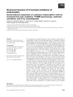
If X-rays of intensity I0 are incident on a sample, as shown schematically in Fig. 1.1a,
the extent of absorption depends on the photon energy E and sample thickness t.
C.S. Schnohr (B)
Institut für Festkörperphysik, Friedrich-Schiller-Universität Jena,
Max-Wien-Platz 1, 07743 Jena, Germany
e-mail:
M.C. Ridgway
Department of Electronic Materials Engineering, Australian National University,
Canberra, ACT 0200, Australia
e-mail:
© Springer-Verlag Berlin Heidelberg 2015
C.S. Schnohr and M.C. Ridgway (eds.), X-Ray Absorption Spectroscopy
of Semiconductors, Springer Series in Optical Sciences 190,
DOI 10.1007/978-3-662-44362-0_1
www.pdfgrip.com
1
2
C.S. Schnohr and M.C. Ridgway
(a)
(b)
I0
μ(E)
sample
It
t
E
Fig. 1.1 a Schematic of incident and transmitted X-ray beam and b absorption coefficient μ(E)
versus photon energy E around an absorption edge
According to Beer’s Law, the transmitted intensity It is
It (t) = I0 e−μ(E)t
(1.1)
where μ(E) is the energy-dependent X-ray absorption coefficient. Over large energy
regions, μ(E) is a smooth function of the photon energy, varying approximately as
μ(E) ∼ d Z 4 /m E 3 [6]. Here d denotes the target density while Z and m are the
atomic number and mass, respectively. Thus, μ(E) decreases with increasing photon
energy. If the latter equals or exceeds the binding energy of a core electron, however,
a new absorption channel is available in which the photon is annihilated thereby
creating a photoelectron and a core-hole. This leads to a sharp increase in absorption
coefficient as shown schematically in Fig. 1.1b. Above the absorption edge, the difference between the photon energy and the binding energy is converted into kinetic
energy of the photoelectron and μ(E) continues to decrease with increasing photon
energy. After a short time of the order of 10−15 s, the core-hole is filled by an electron
from a higher energy state. The corresponding energy difference is released mainly
via fluorescence X-ray or Auger electron emission [4].
1.1.2 Absorption Fine Structure
According to quantum mechanical perturbation theory, the transition rate between
the core level and the final state is proportional to the product of the squared modulus
of the matrix element M and the density of states ρ
μ ∝ |M|2 ρ ∝ | f |H p |i |2 ρ
(1.2)
|i and | f denote the initial and final state, respectively, and H p represents the
interaction Hamiltonian that causes the transition, here the electromagnetic field of
the X-ray photon [2]. Both factors can now cause a modulation of the absorption
www.pdfgrip.com
1 Introduction to X-Ray Absorption Spectroscopy
(a)
3
(b)
continuum
XANES
..
μ(E)
E4
E3
EXAFS
E2
E1
E
Fig. 1.2 a Schematic of the absorption process and b absorption coefficient μ(E) versus photon
energy E including the fine structure above the edge divided into the XANES and EXAFS regions
Fig. 1.3 Schematic showing
the absorbing atom (yellow)
and its first nearest neighbors
(blue). An interference
pattern is created by the
outgoing (solid orange lines)
and reflected (dashed blue
lines) photoelectron waves
coefficient thus creating the X-ray absorption fine structure (XAFS). At the smallest
X-ray energies for which the photon can be absorbed, the photoelectron will be
excited to unoccupied bound states of the absorbing atom as shown schematically in
Fig. 1.2a. This can lead to a strong increase of the absorption coefficient at particular
X-ray energies corresponding to the energy difference between the core level and the
unoccupied states. For higher X-ray energies, the photoelectron is promoted to a free
or continuum state. The wave thus created propagates outwards and is scattered at
neighboring atoms [7] as shown schematically in Fig. 1.3. The outgoing and scattered
waves interfere in a manner that depends on the geometry of the absorber environment
and on the photoelectron wavelength. The latter is inversely proportional to the
photoelectron momentum and therefore changes with photon energy. Thus, the final
state is an energy-dependent superposition of outgoing and scattered waves. Because
the initial state is highly localized at the absorbing atom, the matrix element M in (1.2)
depends on the magnitude of the final state wave function at the site of the absorbing
atom. Constructive or destructive interference of outgoing and scattered waves thus
increases or decreases the absorption probability, creating an energy-dependent fine
structure of the absorption coefficient. Figure 1.2b schematically shows the μ(E) fine
structure as a function of photon energy. Two regions are commonly distinguished,
www.pdfgrip.com
4
C.S. Schnohr and M.C. Ridgway
namely the X-ray absorption near edge structure (XANES) and the extended X-ray
absorption fine structure (EXAFS).
1.1.2.1 XANES
The region very close to the absorption edge is characterized by transitions of the
photoelectron to unoccupied bound states. XANES is therefore sensitive to the chemical bonding, exhibiting for example characteristic features for different oxidation
states of the absorbing atom [4]. The XANES features are also influenced by strong
multiple scattering effects which depend on the three-dimensional geometry of the
crystal structure. This provides a means of distinguishing between different crystal
phases [2]. Theoretical calculations of the fine structure in this region are complex
and the accuracy of such simulations is still limited although significant progress
has been made over recent years [8, 9]. Therefore, analysis typically compares the
measured spectra to those of known standards and quantifies the ratios by which
these standards are present in the sample using linear combination fitting. Often, the
XANES region is also referred to as the near edge X-ray absorption fine structure
(NEXAFS).
1.1.2.2 EXAFS
For photon energies higher than ∼30 eV above the edge, the photoelectron is promoted to a free or continuum state. EXAFS is thus independent of chemical bonding
and depends on the atomic arrangement around the absorber. It contains information about the coordination number, interatomic distances and structural and thermal
disorder around a particular atomic species [7]. EXAFS does not require long-range
order and is applicable to a wide range of ordered and disordered materials therefore
providing a powerful tool for structural analysis. Theoretical calculations of the fine
structure in the EXAFS region have also improved enormously during the last two
decades and simulations with sufficient accuracy are now available [7, 9]. Nevertheless, the measurement of suitable standards still constitutes an important part of the
experimental procedure.
1.2 Theoretical Description
1.2.1 Dipole Approximation
The Hamiltonian H p in (1.2) describes the interaction of the electromagnetic field
of the X-ray photon with the absorbing atom. It is proportional to the scalar product
of the vector potential A of the X-ray field and the electron momentum operator
www.pdfgrip.com
1 Introduction to X-Ray Absorption Spectroscopy
5
p, H p ∝ A · p. In principle, this is a many-body problem where all electrons of
the absorbing atom would have to be considered. Practically, however, it is usually
assumed that only one electron is involved in the transition and corrections due to
many-body effects are added at a later stage. Using this one-electron approximation
together with the dipole approximation for A · p yields
μ ∝ | f |ˆ · r |i |2 ρ
(1.3)
where ˆ denotes the X-ray polarization vector [2, 5]. In most cases the dipole approximation is sufficient, however, quadrupole interactions may become important for
high Z elements and L-edges [2].
Usually, synchrotron radiation is linearly polarized in the horizontal plane [2].
The matrix element in (1.3) therefore depends on the orientation of the line connecting absorber and scattering atom with respect to the X-ray polarization. In randomly
oriented samples or in materials with cubic symmetry this angular dependence is averaged out. In contrast, the orientation dependence must be taken into account for single
crystals or samples with a preferred particle or grain orientation. If unwanted, this
X-ray linear dichroism can be averaged out experimentally by magic angle spinning
of the sample [2]. It can, however, also be used intentionally as an additional source
of information by performing systematic angle-dependent XAS measurements.
The matrix element in (1.3) is further subject to the well-known selection rules
for transitions induced by electromagnetic radiation, i.e. l = ±1 and m = 0, ±1
for electric dipole interactions. Here, l and m denote the orbital angular momentum
quantum number and its projection on the quantization axis, respectively [5]. The
initial core state of the electron is to a good approximation given by an atomiclike state with well-defined quantum numbers l and m. In contrast, the final state
is usually a superposition of wavefunctions with different values of l and m and
only the fraction with the appropriate symmetry is of relevance for the transition [2].
Thus, for K - and L 1 -edges (s states with l = 0) transitions occur only to final states
containing p symmetry while for L 2 - and L 3 -edges ( p states with l = 1) transitions
are only allowed to final states containing s or d symmetry.
1.2.2 Quasi-Particle Model
While the initial state is well approximated by an atomic-like state, the final state is
an excited state characterized by the presence of a core-hole (‘final state rule’). In
the quasi-particle model these final states Ψ f are eigenstates of a Dyson equation1
h Ψf =
1
p2
+ V + Σ(E f ) Ψ f = E f Ψ f
2m
The analog of the Schrödinger equation for excited states.
www.pdfgrip.com
(1.4)
6
C.S. Schnohr and M.C. Ridgway
where E f denotes the energy of the photoelectron in the final state. The
non-Hermitian Hamiltonian h of the final state is characterized by the Coulomb
potential V calculated in the presence of a screened core-hole and by the complex valued and energy-dependent self-energy Σ(E f ) which incorporates many-body effects
and extrinsic inelastic losses [8]. The latter refer to losses during the propagation of
the photoelectron and include excitations such as plasmons or electron-hole pairs and
inelastic scattering in which the photoelectron loses energy [7]. The non-hermicity
of h corresponds to the complex nature of the eigenvalues E f and is responsible
for the finite lifetime of the final state [2]. Relativistic effects become important in
the treatment of the initial atomic core states, especially for high elements, but have
only weak effects on the propagation and scattering of the photoelectron in the final
state [9].
1.2.3 Multiple Scattering Approach
The multiple scattering approach now separates the potential in (1.4) into individual
contributions v R localized at each atomic site R [8]
vR r − R
V +Σ Ef =
(1.5)
R
For electrons with energies of several eV or more above the threshold, the scattering depends mostly on the potential in the core of the neighboring atom which
is approximately spherical [9]. The “muffin-tin” approximation therefore assumes
spherically symmetric atomic potentials out to a finite radius and a constant potential
in between the atoms. The approximation is a good description for close-packed
structures but works less well for open structures. Deviations are most prominent for
small anisotropic systems close to the absorption threshold [2, 9].
Despite this approximation, the calculation of final states turns out to be computationally demanding and very often impractical. The multiple scattering approach
therefore makes use of the photoelectron Green’s function or propagator G in real
space. Applying the identity
−
1
Im G =
π
| f δ E + Ei − E f
f|
(1.6)
f
where E and E i denote photon energy and electron energy in the initial state, respectively, (1.3) can be written as [2]
i|ˆ · r | f δ E + E i − E f
μ∝
f |ˆ · r |i
f
∝ Im i|ˆ · r G ˆ · r |i
www.pdfgrip.com
(1.7)
1 Introduction to X-Ray Absorption Spectroscopy
7
The propagator G can be separated into a contribution Gc stemming from the
central atom and a contribution Gsc due to multiple scattering from the environment,
G = Gc + Gsc . The nature of these contributions then allows expressing μ in terms
of an atomic background μ0 of the embedded absorber and the fine structure χ due to
multiple scattering from the environment, μ = μ0 (1+χ ) [7]. Within this framework,
the fine structure component is now given by
χ = Im eiδ 1 − G 0 T
−1
G 0 eiδ
(1.8)
where G0 denotes the free particle propagator and T represents the scattering matrix
while δ and δ are partial-wave phase shifts [7, 8]. The matrix term in (1.8) can be
written as a series expansion
1 − G0 T
−1
G0 = G0 T G0 + G0 T G0 T G0 + . . .
(1.9)
where the first term is missing due to the definition of G0 [7]. The fine structure
contribution can thus be understood as the sum of individual scattering contributions
arising from all possible paths of the photoelectron from the absorbing atom and
back. The first, second, ... term in (1.9) correspond to single, double, ... scattering
at surrounding atoms. The advantages of this multiple scattering Green’s function
formalism lie in the fact that it treats XANES and EXAFS within the same unified
theory, that it avoids explicit calculation of the final state wave functions and that
it naturally incorporates inelastic losses and other quasi-particle effects [7]. As an
alternative to the path expansion, the fine structure contribution can also be expressed
as the sum of irreducible n-body interactions which contain all scattering contributions due to a particular arrangement of n atoms including the absorber [10, 11].
This approach is directly related to the n-body distribution functions and is thus
particularly suited for the study of highly disordered systems (see Chap. 9).
1.2.4 XANES
In the XANES region, the multiple scattering path expansion of (1.9) only converges
satisfyingly for a few cases typically characterized by short core-hole lifetimes as
given for the absorption by deep core electrons in high Z elements [8]. In most cases,
however, convergence is poor and the multiple scattering expansion has to be carried
out to very high or full order. In principle, this can be done by explicit matrix inversion
of (1.8). Unfortunately, such a procedure is computationally very demanding and
fast parallel Lanczos algorithms have been proposed and implemented to speed up
calculations [8].
Another limitation of the current multiple scattering approach is given by the
muffin-tin approach for the scattering potentials. This approximation usually works
www.pdfgrip.com
8
C.S. Schnohr and M.C. Ridgway
well for sufficiently high photoelectron energies as given in the EXAFS region.
In contrast, the photoelectron energies in the XANES region are small enough for
the scattering to become sensitive to the details of the surrounding potentials. To
avoid this limitation, several full potential approaches have been reported ([2, 5, 8]
and references therein). Band structure calculations based on ground state density
functional theory can also predict the properties of low energy excited states, however,
self-energy effects are typically neglected. Core-hole effects can be included by a
super-cell approach leading to significant improvements of the calculated spectra.
Several full multiple scattering cluster methods represent approaches intermediate
between band structure calculations and path expansion and have been used for a
variety of XANES calculations ([7] and references therein).
Comparison of experimentally determined spectra with ab initio calculations and
even structural fitting of XANES data, especially for small molecules and clusters,
have made tremendous progress in recent years. Nevertheless, theoretical calculations
are still less mature and satisfying than in the EXAFS region. However, given that
XANES is sensitive to both the three-dimensional atomic arrangement and the density
of unoccupied states, improving its theoretical description is a field of much current
effort and further progress can be expected in the near future.
1.2.5 EXAFS
1.2.5.1 EXAFS Equation
The EXAFS is expressed in terms of the fine structure contribution
μ (E) − μ0 (E)
μ (E) − μ0 (E)
∼
μ0 (E)
μ0
χ (E) =
(1.10)
where the energy-dependent denominator is approximated by a constant typically
chosen as the height of the absorption edge, μ0 = μ0 (E 0 ) with E 0 being the
energy of the absorption threshold. Instead of using χ (E), the fine structure is usually
written as a function of the photoelectron wave number k = 2m e (E − E 0 )/ 2 ,
where m e stands for the electron mass and denotes Planck’s constant divided by
2π . Using the multiple scattering path expansion described in Sect. 1.2.3, the fine
structure contribution can be expressed as a sum over the scattering contributions
arising from the various different paths
χ (k) =
S02 N j
j
f j (k)
k R 2j
e−2R j /λ(k) e−2σ j k
× sin 2k R j + 2δc (k) + δ j (k)
www.pdfgrip.com
2 2
(1.11)
1 Introduction to X-Ray Absorption Spectroscopy
9
Paths with the same kinds of scattering atoms and a similar path length have been
grouped under the index j. Equation (1.11) thus directly relates the EXAFS signal to
the structural parameters N j , R j , and σ j2 which represent the number of such similar
paths, the mean path length divided by two and the variation of all path lengths
with index j, respectively. f j (k) = | f j (k)|eiδ j (k) represents the complex scattering
amplitude while δc (k) stands for the phase shift experienced by the photoelectron
wave in the potential of the absorbing atom. λ(k) and S02 denote the energy-dependent
mean free path of the electron and the amplitude reduction factor, respectively.
Except for the factor S02 , (1.11) was first derived by Sayers, Stern, and Lytle for
single scattering paths using the plane-wave approximation [12]. It assumes that
the distance between the absorber-backscatter pair is sufficiently large to treat the
outgoing spherical wave as a plane wave once it reaches the backscattering atom.
For single scattering events, all paths involving the same kind of scattering atom
in the same coordination shell around the absorber are grouped together. The structural parameters N j , R j , and σ j2 then represent the coordination number, the mean
value, and the variance of the corresponding absorber-scatterer distance distribution,
respectively. In case of the first nearest neighbor shell, absorbing and scattering atoms
are usually connected by a real physical bond, and R j and σ j2 signify the mean value
and variance of the bond length distribution. Equation (1.11) has become known as
the ‘standard EXAFS equation’ and has founded the application of XAS as a tool
for structural analysis.
For an accurate calculation of the fine structure contribution, however, multiple
scattering paths, curved-wave effects and many-body interactions must be taken into
account [7]. Nevertheless, χ (k) can still be expressed in the same form as the original
EXAFS equation. This provides a convenient parameterization of the absorber environment in terms of structural parameters for single and multiple scattering paths.
The other quantities of (1.11) implicitly contain the curved-wave and many-body
effects of modern XAS theory as discussed below. The key features of the EXAFS
equation are as follows:
(i) As described in Sect. 1.1.2, the interference pattern depends on the photoelectron energy or wave number and on the distance between the absorbing and
scattering atoms. This is given by the sin[2k R j ] term which causes the oscillatory nature of the fine structure contribution.
(ii) The strength of the scattering and thus the magnitude of the EXAFS depend on
the number and type of the scattering atoms, represented by the coordination
number or degeneracy of paths N j and the modulus of the scattering amplitude | f j (k)|, respectively. Modern XAS theory replaces the original plane-wave
scattering amplitude by an effective curved-wave scattering amplitude for either
single or multiple scattering events. Apart from the dependence on k, the effective scattering amplitudes are also characterized by a weak dependence on r [2].
(iii) The potential of the absorbing or scattering atom leads to a phase shift of the
photoelectron wave represented by δc (k) and δ j (k), respectively. The absorber
potential acts twice on the photoelectron wave, once on the way out and once
www.pdfgrip.com