Atlas of normal radiographic anatomy and anatomic variants in the dog and cat
Bạn đang xem bản rút gọn của tài liệu. Xem và tải ngay bản đầy đủ của tài liệu tại đây (45.6 MB, 227 trang )
i
www.pdfgrip.com
This page intentionally left blank
www.pdfgrip.com
Donald E. Thrall, DVM, PhD, DACVR (Radiology, Radiation Oncology)
Professor
Department of Molecular Biomedical Sciences
College of Veterinary Medicine
North Carolina State University
Raleigh, North Carolina
Ian D. Robertson, BVSc, DACVR
Clinical Associate Professor
Department of Molecular Biomedical Sciences
College of Veterinary Medicine
North Carolina State University
Raleigh, North Carolina
www.pdfgrip.com
3251 Riverport Lane
St. Louis, Missouri 63043
ATLAS OF NORMAL RADIOGRAPHIC ANATOMY
AND ANATOMIC VARIANTS IN THE DOG AND CAT
Copyright © 2011 by Saunders, an imprint of Elsevier Inc.
ISBN: 978-1-4377-0178-4
All rights reserved. No part of this publication may be reproduced or transmitted in any form or by any
means, electronic or mechanical, including photocopying, recording, or any information storage and
retrieval system, without permission in writing from the publisher. Details on how to seek permission,
further information about the Publisher’s permissions policies and our arrangements with organizations such as the Copyright Clearance Center and the Copyright Licensing Agency, can be found at our
website: www.elsevier.com/permissions.
This book and the individual contributions contained in it are protected under copyright by the
Publisher (other than as may be noted herein).
Notices
Knowledge and best practice in this field are constantly changing. As new research and experience
broaden our understanding, changes in research methods, professional practices, or medical treatment may become necessary.
Practitioners and researchers must always rely on their own experience and knowledge in evaluating and using any information, methods, compounds, or experiments described herein. In using
such information or methods they should be mindful of their own safety and the safety of others,
including parties for whom they have a professional responsibility.
With respect to any drug or pharmaceutical products identified, readers are advised to check the
most current information provided (i) on procedures featured or (ii) by the manufacturer of each
product to be administered, to verify the recommended dose or formula, the method and duration
of administration, and contraindications. It is the responsibility of practitioners, relying on their
own experience and knowledge of their patients, to make diagnoses, to determine dosages and the
best treatment for each individual patient, and to take all appropriate safety precautions.
To the fullest extent of the law, neither the Publisher nor the authors, contributors, or editors,
assume any liability for any injury and/or damage to persons or property as a matter of products
liability, negligence or otherwise, or from any use or operation of any methods, products, instructions, or ideas contained in the material herein.
Library of Congress Cataloging-in-Publication Data
Thrall, Donald E.
Atlas of normal radiographic anatomy & anatomic variants in the dog and cat / Donald E. Thrall, Ian
D. Robertson. -- 1st ed.
p. ; cm.
Includes bibliographical references and index.
ISBN 978-1-4377-0178-4 (hardcover : alk. paper) 1. Dogs--Anatomy--Atlases. 2. Cats--Anatomy-Atlases. 3. Veterinary radiography--Atlases. I. Robertson, Ian D. (Ian Douglas), 1958- II. Title.
[DNLM: 1. Cats--anatomy & histology--Atlases. 2. Dogs--anatomy & histology--Atlases. 3.
Radiography--veterinary--Atlases. SF 767.D6]
SF767.D6T57 2011
636.7'0891--dc22
2010027301
Vice President and Publisher: Linda Duncan
Acquisitions Editor: Heidi Pohlman
Senior Developmental Editor: Shelly Stringer
Publishing Services Manager: Julie Eddy
Senior Project Manager: Laura Loveall
Design Direction: Margaret Reid
Printed in the United States
Last digit is the print number: 9 8 7 6 5 4 3 2 1
www.pdfgrip.com
Preface
Becoming a proficient diagnostic radiologist is a long journey. Specialty training leading to board certification entails at least 4 years
of post-DVM structured learning followed by a rigorous multistage
examination. However, board-certified radiologists make up only a
small fraction of all veterinarians who interpret radiographs each
day. Most radiographic studies are being interpreted by competent
veterinarians whose training in image interpretation has been
limited to relatively few contact hours of didactic instruction and
supervised clinical training. All of these veterinarians, as well as
students who are just beginning to develop their interpretive skills,
must have a solid appreciation for normal radiographic anatomy,
anatomic variants, and things that mimic disease, which are affectionately termed “fakeouts” by those of us who spend our lives
interpreting images.
The vastness of normal variation within dogs and cats is staggering. Although the generic cat is relatively standard, dogs come in all
shapes and sizes with innumerable inherent variations that can be
misinterpreted as disease unless recognized as normal. On top of
this inherent variation is the variation introduced by radiographic
positioning that can lead to countless variations in the appearance
of a normal structure. During their training, specialists have this
information grilled into them during many hours of mentored
learning and brow-beating by experienced radiologists. Non-specialists, on the other hand, may have had some introduction to
normal radiographic anatomy during veterinary school, but the acuity of recall becomes dulled by the sheer volume of memory-bank
information needed to be a competent, licensed, contemporary
veterinarian. During one’s education as a student, it is impossible
to be exposed to the range of normal that is likely to be encountered
in practice and then influenced by radiographic positioning. Therefore, there is a real need for a reference source for practicing
veterinarians and students to assist them in the daunting task of
interpreting clinical radiographs competently. This need led to the
development of this atlas.
In this book, we have not only pointed out the identity of
essentially every clinically significant anatomic part of a dog or cat
that can be seen radiographically, we have also included more than
one example of those parts where normal inherent variation can
confuse interpretation. Simply labeling structures in radiographs of
a generic dog or cat is highly inadequate in addressing the mission
of providing a clinically-relevant resource. Additionally, this atlas
includes relevant context to the description of normal anatomy
that only a radiologist can provide. Normal is presented in the
context of how it is modified by the procedure of making the radiograph. Although this is not a radiographic positioning guide, specific technical factors have been included to the extent that their
influence on the image is so great that they must be understood for
the image to be interpreted accurately.
Finally, this book is not simply a picture atlas. Every body part is put
into context with a textural description. This provides a basis for the
reader to understand why a structure appears as it does in radiographs,
and it enables the reader to appreciate variations of normal that are
not included based an understanding of basic radiographic principles.
This may require a bit of effort from the reader in comparison to a
picture atlas, but this small investment of time has the potential for a
big payoff in terms of interpretive ability.
v
www.pdfgrip.com
This page intentionally left blank
www.pdfgrip.com
Acknowledgments
We acknowledge the many dedicated, inquisitive and intelligent veterinary students and radiology residents at North Carolina State University whose
innumerable questions over the years helped us focus on clinically relevant radiographic anatomy and anatomic variants.
vii
www.pdfgrip.com
This page intentionally left blank
www.pdfgrip.com
Contents
1
Introduction, 1
2
The Skull, 17
3
The Spine, 39
4
The Thoracic Limb, 69
5
The Pelvic Limb, 99
6
The Thorax, 127
7
The Abdomen, 169
ix
www.pdfgrip.com
The Images
All images in this book were acquired using a commerciallyavailable indirect digital imaging plate. The images that were
created using this technology have tremendous contrast resolution compared to images acquired using a film-screen system. What this means to the reader is that every image in this
book is the highest quality possible and all regions of the part
being displayed can be assessed. Both thick and thin parts are
assessable, which is something that is impossible when using
film-screen based images. Things that are described in the
text and labeled in the image can be seen. Imagination is
not needed to gain an appreciation for the message being
delivered.
Over 95 percent of the images in this book were acquired on
clinical patients. This introduces a level of relevance that is extremely valuable in terms of putting radiographic anatomy into
perspective. Since the images were derived from clinical patients,
there will be some minor disease that is visible in some images.
This is pointed out where it is relevant to make sure that the reader
does not misinterpret this as part of the normal variation process.
Having absolutely no abnormality in any image could have been
avoided by imaging cadavers, but the breadth of variation in patient size, age, and breed could not have been duplicated in that
instance. The value gained by this variation far outweighs any minor disease that may be seen occasionally.
x
www.pdfgrip.com
Introduction
1
CHAPTER
1
www.pdfgrip.com
Atlas of Normal Radiographic Anatomy and Anatomic Variants in the Dog and Cat
2
HOW TO USE THIS ATLAS
As described in the Preface, a radiographic atlas is intended to help
decide whether any given radiographic appearance is normal or
abnormal. Determining normal from abnormal is one of the most
difficult, if not the most difficult, part of the radiographic interpretive process. No atlas will be able to provide a clear answer to
the “Is it normal or abnormal?” question in every circumstance,
but the material in this book can help guide the decision-making
process.
The best way to use this atlas is to spend some time with it,
and get to know it. Of course, labeled images are provided—
every atlas needs these. But, contrary to a pure picture atlas,
some of the most valuable information in this atlas is contained
within the text. Being familiar with the text, which has been kept
brief and focused, and noting how important principles have
been augmented with illustrative examples can help bolster a
basis for interpretation that extends beyond simple structure
identification.
WHAT IS NORMAL?
Many dogs and cats have congenital, developmental, and degenerative changes that are insignificant clinically but apparent radiographically. These disorders, in many subjects, are manifestations
of selective breeding over many decades. Demonstrating a selection
of these common variations simply acknowledges the existence of
such variations and does not necessarily endorse such breeding
practices. This book demonstrates the morphologic diversity currently present in domestic canine and feline companions that has
come to be commonly accepted as normal.
RADIOGRAPHIC TERMINOLOGY
This book uses the standard method for naming radiographic
projections approved by the American College of Veterinary Radiology (1). In general, this naming method is based on anatomic
directional terms (as defined by the Nomina Anatomica Veterinaria) combined with the point-of-entrance to point-of-exit of the
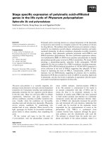
primary x-ray beam. Figure 1-1 diagrams the accepted anatomic
directional terms. Several important concepts are commonly
roxi
mal
l
VIEWING IMAGES
When all radiographic images were made using film-screen systems, a method for consistently hanging the radiographs on a
viewbox was developed. Hanging radiographs the same way for
every subject reduces variation, and the mind becomes more familiar with the way a certain body part should appear in an image. The
basic aspects of that radiograph-hanging system are:
■ Lateral views of any body part should be hung with the subject’s head, or the cranial or rostral aspect of the body part,
facing to the examiner’s left.
■ Ventrodorsal or dorsoventral radiographs of the head, neck, or
trunk should be placed on the viewbox with the cranial or rostral aspect of the subject pointing up toward the ceiling, and
the left side of the subject should be positioned on the examiner’s right side.
■ Lateromedial or mediolateral radiographs of extremities should
be placed on the viewbox with the proximal aspect of the
subject’s limb pointing up toward the ceiling and the cranial or
dorsal aspect of the subject’s limb to the examiner’s left.
■ Caudocranial (palmarodorsal or plantarodorsal) or craniocaudal (dorsopalmar or dorsoplantar) radiographs of an extremity
should be placed on the viewbox with the proximal end of the
extremity pointing up toward the ceiling. There is no convention with regard to whether the medial or lateral side of the
extremity should be placed to the examiner’s left or right. However, in this book, these projections are oriented as though the
subject were being viewed from the front by the examiner. In
other words, a craniocaudal radiograph of the left humerus
would be viewed with the greater tubercle (lateral side) on the
examiner’s left while a craniocaudal radiograph of the right
humerus would be viewed with the greater tubercle (lateral
side) on the examiner’s right.
Although these principles were developed with relevance to how
a radiograph should be displayed on a viewbox, they have carried
over to the digital age and are used to direct how the digital image
should be displayed on a monitor or in print.
STANDARD PROJECTIONS
Most body parts being radiographed are usually subjected to multiple
views at different beam angles. Most commonly, this involves views
made at 90° to each other, termed orthogonal views. Table 1-1 lists the
Dist
ra
Vent
al-p
Dist
al-p
roxi
mal
Dorsal
violated, leading to improper radiographic identification. In summary, these are:
■ The terms anterior and posterior should not be used when describing a radiographic projection.
■ In the head, the term cranial should not be used; rostral is
substituted.
■ In the forelimb, the terms cranial and caudal should not be used
distal to the antebrachiocarpal joint; dorsal and palmar, respectively, are substituted.
■ In the hindlimb, the terms cranial and caudal should not be
used distal to the tarsocrural joint; dorsal and plantar, respectively, are substituted.
Occipitoatlantal junction
Table 1-1
Rostral
Caudal
Cranial
Caudal
Tarsocrural joint
Antebrachiocarpal joint
Dorsal
Palmar
Dorsal
Plantar
Figure 1-1. Diagram of a dog wherein the major directional anatomic
terms, accepted by Nominica Anatomica Veterinaria, are depicted.
Common Orthogonal Views for Major
Body Parts
Body Part
View
Orthogonal View
Skull
Lateral
Spine
Thorax
Lateral
Lateral
Abdomen
Pelvis
Brachium, antebrachium,
thigh, crus
Manus
Pes
Lateral
Lateral
Lateral
Ventrodorsal or
dorsoventral
Ventrodorsal
Ventrodorsal or
dorsoventral
Ventrodorsal
Ventrodorsal
Craniocaudal or
caudocranial
Dorsopalmar
Dorsoplantar
www.pdfgrip.com
Lateral
Lateral
Chapter 1
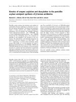
most common orthogonal views for the major body parts. It is critical
to routinely make standard orthogonal views; the complexity of
various anatomic parts is simplified by the repetitive aspect of looking
at the same radiographic projections over and over. When an object
is viewed in an unfamiliar orientation, relevant anatomy becomes
less recognizable (Figure 1-2).
■
Introduction
3
The best solution to the problem of superimposition is to use a
tomographic imaging modality. Tomographic imaging modalities display images in slices, thus avoiding the problem of superimposition
completely. Ultrasound, computed tomography, and magnetic
resonance imaging are all tomographic imaging modalities. Of
course, these modalities are not available for daily use in most practices, and thus the use of oblique radiographs is another method to
solve problems associated with superimposition of structures.
For oblique radiography, projections in addition to the standard
orthogonal projections are acquired; the angle of the primary x-ray
beam with respect to the part being radiographed is somewhere
between the angles used for the standard orthogonal projections.
Typically, this angle is approximately 45 degrees, but other angles
can be used depending on the circumstances. The concept of
oblique radiographic views will be illustrated with a few examples.
The radiographic naming concept previously described is crucial to
understanding this information. That is, radiographic views are
named according to the direction of the primary x-ray beam, from
point-of-entrance to point-of-exit.
This chapter presents examples of oblique radiography based on
radiography of the canine tarsal and canine carpal joints.*
Dorsopalmar or Dorsoplantar View
The dorsopalmar or dorsoplantar view is one of the two basic orthogonal radiographic views of extremities. It is made when the
x-ray beam strikes the dorsal (front) surface of a limb perpendicularly with the cassette or imaging plate behind the limb, perpendicular to the primary x-ray beam. The correct name of this view
depends on whether the limb is a forelimb or hindlimb, and
whether the central portion of the primary x-ray beam is proximal
or distal to the antebrachiocarpal or tarsocrural joints (Table 1-2).
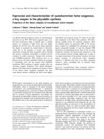
In a dorsopalmar view of a carpus, for example, the x-ray beam
strikes the dorsal surface of the carpus with the image plate behind
the carpus oriented perpendicular to the primary x-ray beam
(Figure 1-3). In this geometric arrangement, only the medial and
lateral aspects of the structure of interest can be visualized in an
unobstructed manner (see Figures 1-3 and 1-4). This does not mean
that only the edges of the structure can be evaluated; the infrastructure can be assessed but the lateral and medial surfaces are primarily
where a periosteal reaction or cortical erosion can be identified.
A
B
Table 1-2
Correct Names for Radiographic Projections
of a Limb Where the X-Ray Beam Strikes the
Front Surface of the Limb and the Cassette
or Imaging Plate Is Directly Behind the Limb
Correct Name of View
Orientation
Dorsopalmar
Primary x-ray beam strikes front surface
of forelimb at antebrachiocarpal joint
or distal. Cassette or imaging plate is
perpendicular to primary x-ray beam.
Primary x-ray beam strikes front surface
of hindlimb at tarsocrural joint or distal. Cassette or imaging plate is perpendicular to primary x-ray beam.
Primary x-ray beam strikes front surface
of forelimb or hindlimb proximal to
antebrachiocarpal joint or tarsocrural
joint. Cassette or imaging plate is perpendicular to primary x-ray beam.
C
Figure 1-2. Dorsoventral (A), lateral (B), and rostocaudal (C) radiographs of
a box turtle. The fact that the subject is a turtle is easily recognizable in A and
B, which are orthogonal radiographs. That the subject is a turtle is less obvious
in C, which is also an orthogonal view with respect to both A and B. However,
this view is acquired much less frequently, making it unfamiliar with most
interpreters. In addition, the fact that there are eggs in the coelom would not
be determined if only view C is being consulted. This example emphasizes the
need for at least two orthogonal views of any body part being radiographed
and the need to use the same standardized views in every subject.
Dorsoplantar
Craniocaudal
OBLIQUE PROJECTIONS
For anatomically complex regions, such as the carpus, tarsus, manus, and pes, two orthogonal radiographic views are not adequate
to assess all aspects of the structures. There is too much superimposition in two orthogonal views for all surfaces to be assessed
completely, and important lesions can be missed. The objective of
radiographing complex structures using multiple views is to project
as many surfaces or edges in the most unobstructed manner possible. The internal structure of complex regions can sometimes be
assessed, even with overlapping, because of the penetrating nature
of x-rays. However, the assessment of a complex structure is going
to be most accurate when the structure, or at least its edge, is
projected in an unobstructed manner.
Lateral View
The complementary orthogonal view to the dorsopalmar (or dorsoplantar) view of the extremities is the lateral view. It is made when
the x-ray beam strikes the side surface of a limb with the cassette or
imaging plate on the opposite side of the limb, perpendicular to
the primary x-ray beam (Figure 1-5). These views are most often referred to as lateral views, although lateromedial or mediolateral is
*The colorized surface renderings in Figures 1-4, 1-6, 1-8, and 1-10 were graciously
prepared by Sarena Sunico, DVM.
www.pdfgrip.com
4
Atlas of Normal Radiographic Anatomy and Anatomic Variants in the Dog and Cat
Dorsal
Lateral
U
A
I
R
Medial
Palmar
Figure 1-3. The proximal row of carpal bones is shown as though the carpus was sliced transversely at that level.
The x-ray beam strikes the carpal bones from the front. As can be seen, the only surfaces that can be projected in
an unobstructed fashion are the medial side of the radial carpal bone (R) and the lateral side of the ulnar carpal
bone (U); dotted arrows indicate these surfaces. These are the only surfaces that can be evaluated for surface lesions, such as periosteal reaction or cortical lysis. Other surfaces will be superimposed on another structure and
cannot be assessed accurately.
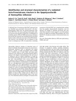
Figure 1-4. The left panel shows a dorsoplantar radiograph of a canine tarsus. The middle panel shows a threedimensional rendering of a normal right canine tarsus as seen from the perspective of the x-ray beam when making
a dorsoplantar radiograph. The right panel shows a three-dimensional rendering of a normal right canine tarsus, also
as seen from the perspective of the x-ray beam when making a dorsoplantar radiograph, but where each bone has
been colorized (see Color Plate 1). The colorized version makes it easier to comprehend the extent of overlap. Note
in the radiograph how the only aspects of the tarsal bones that are projected in an unobstructed fashion where the
surface can be evaluated are the medial and lateral aspects of the tarsus.
Dorsal
Lateral
U
I
R
Medial
A
Palmar
Figure 1-5. The proximal row of carpal bones is shown as if the carpus was sliced transversely at that level. The
x-ray beam strikes the structure from the medial side, in this instance a mediolateral view. As can be seen, the
only surfaces that will be projected in an unobstructed fashion are the dorsal surface of the intermediate carpal
bone (I) and the palmar side of the accessory carpal bone (A); dotted arrows indicate these surfaces. These surfaces are the only surfaces that can be evaluated for surface lesions, such as periosteal reaction or cortical lysis.
www.pdfgrip.com
Chapter 1
more correct depending on whether the lateral or medial aspect of
the limb, respectively, is struck by the primary x-ray beam.
In a mediolateral view of a carpus, for example, the x-ray beam
strikes the medial surface of the carpus with the image plate lateral
to the carpus, oriented perpendicularly to the primary x-ray beam
(see Figure 1-5). In this geometric arrangement, only the dorsal and
palmar aspects of the structure of interest can be visualized in an
unobstructed manner (see Figures 1-5 and 1-6). This does not mean
that only the edges of the structure can be evaluated; the infrastructure can be assessed but the dorsal and palmar/plantar surfaces are
the only surfaces where a surface change, such as a periosteal reaction or cortical erosion, can be identified.
■
Introduction
5
Oblique Views
In oblique views of the carpus or tarsus, the entrance point of the
primary x-ray beam is intentionally shifted to some location between dorsal and lateral or between dorsal and medial. Typically
this position is approximately midway between dorsal and lateral,
or between dorsal and medial, but other angles can be used
depending on the circumstances.
For the oblique view where the entrance point is shifted midway
between dorsal and medial, the correct terminology depends on
whether the structure of interest is a forelimb or hindlimb, and
whether the point of interest is proximal to the antebrachiocarpal or
tarsocrural joints (Table 1-3). In a dorsal 45° medial-palmarolateral
Figure 1-6. The left panel shows a mediolateral radiograph of a canine tarsus. The middle panel shows a threedimensional rendering of a normal right canine tarsus as seen from the perspective of the x-ray beam when
making a mediolateral radiograph. The right panel shows a three-dimensional rendering of a normal right
canine tarsus, also as seen from the perspective of the x-ray beam when making a mediolateral radiograph, but
where each bone has been colorized (see Color Plate 2). The colorized version makes it easier to comprehend
the extent of overlap. Note in the radiograph how the only aspects of the tarsal bones that are projected in an
unobstructed fashion are the dorsal and plantar aspects of the tarsus and the cranial and caudal aspects of the
tibia. The proximal surface of the calcaneus is also visible in this projection because it is not superimposed on
any other structure.
Table 1-3
Correct Names for Oblique Radiographic Projections of a Limb Where the X-Ray Beam Strikes the Front
Surface of the Limb Midway Between the Front and Side and the Cassette or Imaging Plate Is Behind
the Limb and Perpendicular to the Primary X-Ray Beam
Correct Name of View
Orientation
Dorsal 45° lateral-palmaromedial
Primary x-ray beam strikes front surface of forelimb midway between dorsal and lateral
aspects, at antebrachiocarpal joint or distal. Cassette or imaging plate is perpendicular to
primary x-ray beam. Results in projection of dorsomedial and palmarolateral aspects of
region of interest (see Figure 1-9).
Primary x-ray beam strikes front surface of hindlimb midway between dorsal and lateral
aspects, at tarsocrural joint or distal. Cassette or imaging plate is perpendicular to primary
x-ray beam. Results in projection of dorsomedial and plantarolateral aspects of region of
interest. (see Figure 1-10).
Primary x-ray beam strikes front surface of forelimb midway between dorsal and medial
aspects, at antebrachiocarpal joint or distal. Cassette or imaging plate is perpendicular to
primary x-ray beam. Results in projection of dorsolateral and palmaromedial aspects of
region of interest (see Figure 1-7).
Primary x-ray beam strikes front surface of hindlimb midway between dorsal and medial
aspects, at tarsocrural joint or distal. Cassette or imaging plate is perpendicular to primary
x-ray beam. Results in projection of dorsolateral and plantaromedial aspects of region of
interest (see Figure 1-8).
Primary x-ray beam strikes front surface of forelimb or hindlimb midway between dorsal and
lateral aspects, proximal to antebrachiocarpal or tarsocrural joint. Cassette or imaging plate
is perpendicular to primary x-ray beam. Results in projection of craniomedial and caudolateral aspects of region of interest.
Primary x-ray beam strikes front surface of forelimb or hindlimb midway between dorsal and
medial aspects, proximal to antebrachiocarpal or tarsocrural joint. Cassette or imaging plate
is perpendicular to primary x-ray beam. Results in projection of craniolateral and caudomedial aspects of region of interest.
Dorsal 45° lateral-plantaromedial
Dorsal 45° medial-palmarolateral
Dorsal 45° medial-plantaromedial
Cranial 45° lateral-caudomedial
Cranial 45° medial-caudolateral
www.pdfgrip.com
6
Atlas of Normal Radiographic Anatomy and Anatomic Variants in the Dog and Cat
oblique (D45ºM-PaLO, often abbreviated to DM-PaLO) view of a
carpus, for example, the x-ray beam strikes the dorsal surface of the
carpus midway between dorsal and medial with the image plate
perpendicular to the primary x-ray beam (Figure 1-7). In this geometric arrangement, only the dorsolateral and palmaromedial
(plantaromedial for hindlimb) aspects of the structure can be visualized in an unobstructed manner (see Figures 1-7 and 1-8).
For the oblique view where the entrance point is shifted midway
between dorsal and lateral, the correct terminology depends on
whether the structure of interest is a forelimb or hindlimb, and
whether the point of interest is proximal to the antebrachiocarpal or
tarsocrural joint (see Table 1-3). In a dorsal 45° lateral-palmaromedial
oblique (D45ºL-PaMO, often abbreviated to DL-PaMO) view of
a carpus, for example, the x-ray beam strikes the dorsal surface of
the carpus midway between dorsal and lateral with the image
U
Lateral
A
Dorsal
I
R
Medial
PA
LM
SU ARO
RF M
AC ED
E IAL
L
RA
E
T E
LA C
O FA
S
R UR
DO S
plate perpendicular to the primary beam (Figure 1-9). In this
geometric arrangement, only the dorsomedial and palmarolateral
(plantarolateral for hindlimb) aspects of the structure can be visualized in an unobstructed manner (see Figures 1-9 and 1-10).
Not all oblique views involve the use of a primary x-ray beam
angle between dorsal and lateral or dorsal and medial. For example,
there are views of the bicipital groove (cranioproximal-craniodistal
flexed view of shoulder) and proximal surface of the talus (dorsoplantar flexed tarsus) that are special oblique views designed to
make certain portions of the skeleton more conspicuous. Having a
good knowledge of how radiographs are named reduces confusion
when naming these more unconventional views and in understanding exactly why the images appear the way they do. These less
frequently used oblique views are explained in more detail in the
sections in which they are illustrated.
Palmar
Plantaromedial surface
Dorsolateral surface
Figure 1-7. In this drawing, the proximal row of carpal bones is shown as though the carpus was sliced transversely
at that level. The x-ray beam strikes the structure approximately midway between the dorsal and medial aspects; thus
the correct name of this projection is a dorsal 45° medial-palmarolateral view. As can be seen, the only surfaces that
will be projected in an unobstructed fashion are the palmaromedial surface of the radial carpal bone (R) and the
dorsolateral surface of the ulnar carpal bone (U); dotted arrows indicate these surfaces. These are the only surfaces
that can be evaluated for surface lesions, such as periosteal reaction or cortical lysis. Other surfaces will be superimposed on another structure.
Figure 1-8. The left panel shows a dorsal 45° medial-plantarolateral radiograph of a canine tarsus. The middle
panel shows a three-dimensional rendering of a normal right canine tarsus as seen from the perspective of the x-ray
beam when making a dorsal 45° medial-plantarolateral radiograph. The right panel shows a three-dimensional
rendering of a normal right canine tarsus, also as seen from the perspective of the x-ray beam when making a dorsal
45° medial-plantarolateral radiograph, but where each bone has been colorized (see Color Plate 3). The colorized
version makes it easier to comprehend the extent of overlap. Note in the radiograph how the only aspects of the
tarsal bones that are projected in an unobstructed fashion are the dorsolateral and plantaromedial aspects of the
tarsus. Even though the proximal aspect of the calcaneus is plantarolateral, it can still be seen in this radiograph
because it extends sufficiently proximal that it will not be superimposed on the tibia in either oblique view.
www.pdfgrip.com
Chapter 1
Dorsal
■
Introduction
7
DO
R
SU SO
RF ME
AC DI
E A
L
U
Lateral
I
R
A
Medial
AL
R
TE
LA E
O AC
AR RF
LM SU
PA
Palmar
Plantarolateral surface
Dorsomedial surface
Figure 1-9. This drawing shows the proximal row of carpal bones as though the carpus has been sliced transversely at that level. The x-ray beam strikes the structure approximately midway between the dorsal and lateral
aspects; this is a dorsal 45° lateral-palmaromedial view. As can be seen, the only surfaces that will be projected
in an unobstructed fashion are the palmarolateral surface of the accessory carpal bone (A) and the dorsomedial
surface of the radial carpal bone (R); dotted arrows indicate these surfaces. These are the only surfaces that can
be evaluated for surface lesions, such as periosteal reaction or cortical lysis. Other surfaces will be superimposed
on another structure.
Figure 1-10. The left panel shows a dorsal 45° lateral-plantaromedial radiograph of a canine tarsus. The middle
panel shows a three-dimensional rendering of a normal right canine tarsus as seen from the perspective of
the x-ray beam when making a dorsal 45° lateral-plantaromedial radiograph. The right panel shows a threedimensional rendering of a normal right canine tarsus, also as seen from the perspective of the x-ray beam when
making a dorsal 45° lateral-plantaromedial radiograph, but where each bone has been colorized (see Color
Plate 4). The colorized version makes it easier to comprehend the extent of overlap. It is important to note that
the dorsal surface of the radiograph is oriented to the viewer’s left, whereas the dorsal surfaces of the threedimensional models are oriented to the viewer’s right. As the three-dimensional models are anatomically correct
models of a right tarsus, this is the orientation that the radiographer would see. However, when radiographs are
viewed, the cranial or dorsal surface of the structure is always oriented to the viewer’s left; this explains the
difference in orientation of the radiograph versus the models in this figure only. Note in the radiograph how
the only aspects of the tarsal bones that are projected in an unobstructed fashion are the dorsomedial and
plantarolateral aspects of the tarsus.
By using oblique radiographic views, all surfaces of a complex
joint can be evaluated for periosteal reaction and cortical lysis, and
small fragments can be localized accurately. It is important to understand the anatomy of oblique views to draw accurate conclusions
regarding the location of any abnormality and to acquire the correct oblique view when interrogating specific anatomic regions.
PHYSEAL CLOSURE
Juvenile orthopedic disorders are common, particularly in dogs.
Many arise from disruption to normal physeal development. Breed,
genetics, nutrition, intercurrent disease, activity, and trauma can all
effect skeletal development adversely. Some understanding of the
radiographic appearance of normal physeal maturation and the age
at which this occurs is a prerequisite to the identification and management of such disorders. Table 1-4 provides an overview of when
the various ossification centers appear, and Table 1-5 shows when
physes are typically radiographically closed. It should be noted that
there is considerable variation in physeal closure, and these tables
are designed to act only as guides. The tables reflect a compilation of
data from multiple sources. Table 1-6 documents the approximate
ages at which the fusion of skull bones occurs in both canines and
felines. Figures 1-11 through 1-16 diagrammatically show the canine
long bone and joint morphology from 1 month to 8.5 months.
Figures 1-17 through 1-24 diagrammatically show the feline long
bone and joint morphology from 3.5 weeks to 16.5 months.
www.pdfgrip.com
8
Atlas of Normal Radiographic Anatomy and Anatomic Variants in the Dog and Cat
Table 1-4
Approximate Ages at which Ossification Centers Appear (Canine and Feline)
Site
Scapula
Body
Supraglenoid tubercle
Humerus
Proximal epiphysis (head and tubercles)
Diaphysis
Condyle
Medial epicondyle
Radius
Proximal epiphysis
Diaphysis
Distal epiphysis
Ulna
Olecranon tubercle
Diaphysis
Anconeal process
Distal epiphysis
Carpus
Radial carpal (3 centers)
Other carpal bones
Accessory carpal
Diaphysis
Epiphysis
Sesamoid bone in abductor pollicis longus
Metacarpus/metatarsus
Diaphysis of 1-5
Proximal epiphysis of MC1
Distal epiphysis of MC2-5
Palmar sesamoid bones
Dorsal sesamoid bones
Phalanges (fore and hind)
P1
Diaphysis of digits 1-5
Proximal epiphysis digit 1
Distal epiphysis digits 2-5
P2
Diaphysis of digits 2-5
Proximal epiphysis of digits 2-5
P3 (one ossification center)
Pelvis
Ilium/ischium/pubis
Acetabular bone
Iliac crest
Ischial tuberosity
Ischial arch
Femur
Greater trochanter
Lesser trochanter
Head
Diaphysis
Distal epiphysis
Stifle sesamoid bones
Patella
Fabellae
Popliteal sesamoid
Tibia
Tibial tuberosity
Proximal epiphysis
Diaphysis
Distal epiphysis
Medial malleolus
Fibula
Proximal epiphysis
Diaphysis
Distal epiphysis
Canine
Feline
Birth
6-7 weeks
Birth
7-9 weeks
1-2 weeks
Birth
2-3 weeks
6-8 weeks
1-2 weeks
Birth
2-4 weeks
6-8 weeks
3-5 weeks
Birth
2-4 weeks
2-4 weeks
Birth
2-4 weeks
6-8 weeks
Birth
6-8 weeks
5-6 weeks
4-5 weeks
Birth
3-6 weeks
2 weeks
3-8 weeks
3-8 weeks
2 weeks
6-7 weeks
4 months
3-8 weeks
3-8 weeks
Birth
5-7 weeks
3-4 weeks
2 months
4 months
Birth
Birth
5-7 weeks
4-6 weeks
Birth
3-4 weeks
3-4 weeks
Birth
4-6 weeks
Birth
Birth
4 weeks
Birth
Birth
2-3 months
4-5 months
3-4 months
6 months
Birth
7-9 weeks
7-9 weeks
1-2 weeks
Birth
3-4 weeks
5-6 weeks
6-7 weeks
2 weeks
Birth
1-2 weeks
6-9 weeks
3 months
3-4 months
8-9 weeks
10 weeks
7-8 weeks
2-4 weeks
Birth
2-4 weeks
3 months
6-7 weeks
2 weeks
Birth
2 weeks
8-10 weeks
Birth
4-7 weeks
6-7 weeks
Birth
3-4 weeks
www.pdfgrip.com
3-4 weeks
3 weeks
2-2.5 months
Chapter 1
Table 1-4
■
Introduction
9
Approximate Ages at which Ossification Centers Appear (Canine and Feline)—cont’d
Site
Tarsus
Talus
Calcaneus
Tuber calcanei
Diaphysis
Central tarsal bone
First and second tarsal bones
Third tarsal bone
Fourth tarsal bone
Spine
Atlas, three centers of ossification
Neural arch (bilateral)
Intercentrum
Axis, seven centers of ossification
Centrum of proatlas
Centrum 1
Intercentrum 2
Centrum 2
Neural arch (bilateral)
Caudal epiphysis
Cervical, thoracic, lumbar, sacral vertebrae
Paired neural arches and centrum
Cranial and caudal epiphyses*
Canine
Feline
Birth
Birth
6 weeks
Birth
3 weeks
4 weeks
3 weeks
2 weeks
4 weeks
Birth
4-7 weeks
4-7 weeks
4-7 weeks
4-7 weeks
Birth
Birth
6 weeks
Birth
3 weeks
Birth
Birth
2 weeks
Birth
2 weeks
*Epiphyses are often absent in the last 1-2 caudal vertebrae.
Table 1-5
Approximate Age When Physeal Closure Occurs (Canine and Feline)
Bone
Physis
Canine
Feline
Scapula
Supraglenoid tubercle
4-7 months
3.5-4 months
Humerus
Proximal
Medial epicondyle
Condyle to shaft
Condyle (lateral and medial parts)
Proximal
Distal
Anconeal process
Olecranon tuberosity
Distal
10-15 months
6-8 months
6-8 months
6-10 weeks
7-10 months
10-12 months
Ͻ5 months
7-10 months
9-12 months
18-24 months
Proximal
Distal
6-7 months
6-7 months
4.5-5 months
4.5-5 months
Proximal
Acetabular
Ischiatic tuberosity
Ilial crest
Pubic symphysis
Head, capital physis
Greater trochanter
Lesser trochanter
Distal physis
Tibial tuberosity
Tibial plateau
Distal physis
Medial malleolus
Proximal
Distal (lateral malleolus)
6-7 months
3-5 months
10-12 months
24-36 months
4-5 months
8-11 months
9-12 months
9-12 months
9-12 months
10-12 months
9-10 months
12-15 months
3-5 months
10-12 months
12-13 months
Radius
Ulna
Metacarpus/metatarsus
MC1
MC2-5
Phalanges (fore and hind)
P1 and P2
Pelvis
Femur
Tibia
Fibula
3.5-4 months
3.5 months
5-7 months
14-22 months
9-13 months
14-25 months
7-11 months
13-19 months
9-10 months
12-19 months
10-12 months
13-18 months
10-14 months
Continued
Physes most commonly associated with clinical disorders in italic.
www.pdfgrip.com
10
Atlas of Normal Radiographic Anatomy and Anatomic Variants in the Dog and Cat
Table 1-5
Approximate Age When Physeal Closure Occurs (Canine and Feline)—cont’d
Bone
Tarsus
Calcaneus
Spine ossification centers
Atlas
Axis
Cervical, thoracic, lumbar
Sacrum
Caudal
Physis
Canine
Tuberosity
6-7 months
Arches fuse
Intercentrum
Centrum of proatlas + C1
Intercentrum 2, centrum 1, and
centrum 2
Neural arches (bilateral)
Caudal physis
Cranial physis
Caudal physis
Cranial and caudal physes
Cranial and caudal physes
3-4 months (106 d)
3-4 months (115 d)
100-110 d
3.3-5 months
Table 1-6
7-10 months
8-11 months
Approximate Age When Fusion of Skull
Bones Occurs (Canine and Feline)
Center of Ossiϐication
Age
Occipital
Basilar part
Squamous part
Interparietal part
Body/wings of presphenoid
Body/wings of basisphenoid
Basisphenoid and presphenoid
Sphenobasilar suture
Interparietal suture
Interfrontal suture
Petrosquamous suture
Intermandibular symphysis
2.5-5 months
3-4 months
Before birth
Before birth
3-4 years
1-2 years
8-10 months
2-3 years
3-4 years
2-3 years
Never or very late
Parietal
Frontal
Temporal
Mandible
57
30 days
7-12 months
7-10 months
8-12 months
7-12 months
7-12 months
Bone
Sphenoid
29
Feline
72
85
120
169
261
Figure 1-11. Canine shoulder, lateral and caudocranial views. Age in days. (Modified with permission from
Schebitz H, Wilkens H: Atlas of Radiographic Anatomy of the Dog and Cat, ed 4, Philadelphia, 1986, Saunders.).
www.pdfgrip.com
Chapter 1
29
57
29
72
57
85
72
120
85
169
120
■
Introduction
261
169
261
Figure 1-12. Canine elbow, lateral and craniocaudal view. Age in days. (Modified with permission from Schebitz
H, Wilkens H: Atlas of Radiographic Anatomy of the Dog and Cat, ed 4, Philadelphia, 1986, Saunders.)
29
57
72
85
120
169
261
Figure 1-13. Canine manus, dorsopalmar view. Age in days. (Modified with permission from Schebitz H,
Wilkens H: Atlas of Radiographic Anatomy of the Dog and Cat, ed 4, Philadelphia, 1986, Saunders.)
www.pdfgrip.com
11
12
Atlas of Normal Radiographic Anatomy and Anatomic Variants in the Dog and Cat
29
57
72
85
120
169
261
Figure 1-14. Canine left hemipelvis, ventrodorsal view. Age in days. (Modified with permission from Schebitz H,
Wilkens H: Atlas of Radiographic Anatomy of the Dog and Cat, ed 4, Philadelphia, 1986, Saunders.)
29
29
57
57
72
72
85
85
120
120
169
169
Figure 1-15. Canine stifle, lateral and craniocaudal view. Age in days. (Modified with permission from Schebitz H,
Wilkens H: Atlas of Radiographic Anatomy of the Dog and Cat, ed 4, Philadelphia, 1986, Saunders.)
www.pdfgrip.com
261
261
Chapter 1
29
57
72
85
120
169
■
Introduction
261
Figure 1-16. Canine pes, dorsoplantar view. Age in days. (Modified with permission from Schebitz H, Wilkens H:
Atlas of Radiographic Anatomy of the Dog and Cat, ed 4, Philadelphia, 1986, Saunders.)
24
45
102
157
255
297
366
404
499
Figure 1-17. Feline shoulder, lateral and caudocranial view. Age in days. (Modified with permission from
Schebitz H, Wilkens H: Atlas of Radiographic Anatomy of the Dog and Cat, ed 4, Philadelphia, 1986, Saunders.)
www.pdfgrip.com
13
14
Atlas of Normal Radiographic Anatomy and Anatomic Variants in the Dog and Cat
24
45
102
157
255
297
366
404
499
Figure 1-18. Feline elbow, lateral and craniocaudal view. Age in days. (Modified with permission from
Schebitz H, Wilkens H: Atlas of Radiographic Anatomy of the Dog and Cat, ed 4, Philadelphia, 1986, Saunders.)
24
45
102
157
255
297
366
404
499
Figure 1-19. Feline distal antebrachium and carpus, lateral view. Age in days. (Modified with permission from
Schebitz H, Wilkens H: Atlas of Radiographic Anatomy of the Dog and Cat, ed 4, Philadelphia, 1986, Saunders.)
24
45
102
157
255
297
366
402
Figure 1-20. Feline manus, dorsomedial plantarolateral oblique view. Age in days. (Modified with permission from
Schebitz H, Wilkens H: Atlas of Radiographic Anatomy of the Dog and Cat, ed 4, Philadelphia, 1986, Saunders.)
www.pdfgrip.com
499