Honeywell DC1000 Series Hướng dẫn sử dụng bộ điều khiển Honeywel DC1000
Bạn đang xem bản rút gọn của tài liệu. Xem và tải ngay bản đầy đủ của tài liệu tại đây (815.44 KB, 32 trang )
DC1000 SERIES
DIGITAL CONTROLLER
PRODUCT MANUAL
Industrial Measurement & Control
51-52-25-113
Issue1
March 2004
DC1010/1020/1030/1040 Product Manual
Copyright, Notices, and Trademarks
Printed in Taiwan - © Copyright 2004 Honeywell International Inc.
Issue 1 - March 2004
Warranty / Remedy
Honeywell warrants goods of its manufacture as being free to defective materials and faulty
workmanship. Contact your local sales office for warranty information. If warranted goods are
returned to Honeywell during the period of coverage, Honeywell will repair or replace without charge
those items it finds defective. The foregoing is Buyer’s sole remedy and is in lieu of all other
warranties, expressed or implied, including those of merchantability and fitness for a
particular purpose. Specifications may change without notice. The information we supply is believed
to be accurate and reliable as of this printing. However, we assume no responsibility for its use.
While we provide application assistance personally, through our literature and the Honeywell web site,
it is up to the customer to determine the suitability of the product in the application.
© Copyright 2004 Honeywell International Inc.
Sales and Service
Honeywell serves its customers through a worldwide network of sales offices and distributors. For
application assistance, current specifications, pricing, or name of the nearest Authorized Distributor,
contact your local sales office. See back page
Industrial Measurement and Control
Honeywell Korea
191 HanGangRo 2ga, YongSanGu
Seoul, Korea
DC1010/1020/1030/1040 Product Manual
Contacts
World Wide Web
The following lists Honeywell’s World Wide Web sites that will be of interest to our customers
Corporate
/>
Automation & Control Solutions
/>
Industrial Measurement & Control
/>
Telephone
Contact us by telephone at the numbers listed below
United States and Canada
1-800-423-9883
Technical. Support
1-888-423-9883
Q&A Faxback (TACFACS)
1-800-525-7439
Service
Asia Pacific
+ (65) 6355 2828
Asia Pacific Headquarters
Europe
+ (32) 2 728 2111
Honeywell PACE, Brussels, Belgium
Latin America
+ (854) 845 2600
Honeywell, Sunrise, Florida U.S.A
DC1010/1020/1030/1040 Product Manual
Symbol Definitions
The following advisory convention is used in this document to denote certain conditions.
Symbol
Definition
CAUTION
This CAUTION symbol on the equipment refers the user to the Product Manual for
additional information. In this manual, this symbol appears next to required information.
Failure to comply with these instructions may result in product damage.
WARNING
PERSONAL INJURY: Risk of electrical shock. This symbol warns the user of the potential
shock hazard where HAZARDOUS LIVE voltages greater than 30 Vrms, 42.4 Vpeak, or 60
Vdc may be accessible.
Failure to comply with these instructions could result in death or serious injury.
DC1010/1020/1030/1040 Product Manual
Contents
1.
Overview ............................................................................................................................ 1
1.1
Introduction.............................................................................................................................1
2.
Installation ......................................................................................................................... 2
2.1
Model Number Interpretation..................................................................................................2
2.2
Specification ...........................................................................................................................3
2.3
Mounting.................................................................................................................................4
2.4
External Dimension ................................................................................................................4
2.4.1
DC1010...........................................................................................................................4
2.4.2
DC1020...........................................................................................................................5
2.4.3
DC1030...........................................................................................................................5
2.4.4
DC1040...........................................................................................................................5
2.5
Wiring Diagrams.....................................................................................................................6
2.5.1
DC1010...........................................................................................................................7
2.5.2
DC1020...........................................................................................................................8
2.5.3
DC1030...........................................................................................................................9
2.5.4
DC1040.........................................................................................................................10
3.
Configuration ................................................................................................................... 11
3.1
Operator Interface ................................................................................................................ 11
3.2
MODE Access ......................................................................................................................12
3.3
MODEs .................................................................................................................................13
3.3.1
Operation ......................................................................................................................13
3.3.2
Configuration 1 .............................................................................................................14
3.3.3
Configuration 2 .............................................................................................................15
3.4
Alarms ..................................................................................................................................17
3.4.1
Deviation Alarm.............................................................................................................17
3.4.2
Absolute Value Alarm....................................................................................................18
3.4.3
Program Alarm..............................................................................................................19
3.4.4
System Alarm................................................................................................................19
3.5
Function Lock .......................................................................................................................20
4.
Input Codes ...................................................................................................................... 21
4.1
Thermocouples.....................................................................................................................21
4.2
RTDs ....................................................................................................................................22
4.3
Linear Inputs.........................................................................................................................22
5.
Operation.......................................................................................................................... 23
5.1
Type of Control .....................................................................................................................23
5.1.1
Manual Operation .........................................................................................................23
5.1.2
ON/OFF Control............................................................................................................23
5.1.3
PID Control ...................................................................................................................23
5.2
Set Point ...............................................................................................................................23
5.3
Alarm Set Point ....................................................................................................................23
6.
Error Message................................................................................................................... 24
DC1010/1020/1030/1040 Product Manual
1.
Overview
1.1
Introduction
Function
The DC1000 family of microprocessor based controllers combine a
high degree of functionality and reliability in 4 different formats: 1/16
DIN, 1/8 DIN, 3/16 DIN, and 1/4 DIN.
With a typical accuracy of ± 0.5% of span, the DC1000 is an ideal
controller for regulating temperature and other process variables in a
variety of applications including dryers, semiconductor packaging &
testing, plastic processing, packaging machinery, painting & coating,
and climatic chambers.
Easy to Configure
Two different configuration levels provide easy access to parameters.
A 4-digit security code prevents unauthorized changes. Parameters
can also be hidden to the user to prevent improper configuration of
the unit.
Various Control Algorithms
The DC1000 series of controllers provides several different
algorithms:
PID or ON/OFF Control
Hear/Cool Algorithms with 2 different PID sets
Motor Position Control without slidewire feedback
Single Phase Control with/without zero crossover control
Three Phase Control with/without zero crossover control
Mount Anywhere
The DC1000 family is industrial control equipments that must be
panel mounted. The wiring terminals must be enclosed within the
panel. The DC1000 is environmentally hardened and, when suitably
enclosed, can be mounted virtually anywhere in plant or factory; on
the wall, in a panel, or even on the process machine. It withstands
ambient temperature up to 50°C (122°F).
CE Conformity (Europe)
This product is in conformity with the protection requirements of the
following European Council Directive: 73/23/EEC, the Low Voltage
Directive, and 89/336/EEC, the EMC Directive. Conformity of this
product with any other “CE Mark” Directive(s) is not guaranteed.
Enclosure Rating: Panel-mounted equipment rating IP00. This
controller must be panel mounted and all terminals must be enclosed
within the panel. Front panel IP65 (IEC 529) option is available.
DC1010/1020/1030/1040 Product Manual
1
2.
Installation
WARNING
Local Regulations regarding electrical & safety must be observed.
Failure to comply with these instructions could result in death or serious injury.
2.1
Model Number Interpretation
DC10
0
-
-
-
Size
1
48*48
2
48*96
3
72*72
4
96*96
Table III
Manual
E English
C Chinese
K Korean
Program
Input
C
None
R
RTD
P
Program
T
TC
L
Linear
Table I
Table II
Output 1
Output 2
Alarm
Aux.
Input 2
0
None
0
None
0
None
0
None
0
None
0
None
1
Relay
1
Relay
1
1 alarm
1
4~20mA
1
4~20mA
1
RS-232
2
Volt Pulse
2
Volt Pulse
2
2 alarms
2
0~20mA
2
0~20mA
2
RS-485
3
4~20mA
3
4~20mA
3
3 alarms
A
0~5V
A
0~5V
5
1ϕ SSR
A
0~5V
B
0~10V
B
0~10V
6
3ϕ SSR
B
0~10V
C
1~5V
C
1~5V
7
Motor V
C
1~5V
D
2~10V
D
2~10V
8
1ϕ SCR
D
2~10V
9
3ϕ SCR
A
0~5V
B
0~10V
C
1~5V
D
2~10V
DC1010/1020/1030/1040 Product Manual
2
Comm.
2.2
Specification
TECHNICAL DATA
Type of Input
PV Input
Indication
Control Mode
Output
Alarm
Aux. Output
2nd Input
(RSP)
Program
Communication
Input Sampling Time
Input Resolution
PV/SP Indication
Constant Value Storage System
Indication Accuracy
Proportional Band (P)
Integral Time (I)
Derivative Time (D)
Cycle Time
Relay Output
Voltage Output
Linear Output
Motor Control Output
Others
Channel
Mode
Timer
Output Signal
Type of Output
Type of Input
Sampling Time
Pattern/Segment
Availability
Type of Communication
Rated Power Supply
Voltage & Frequency
Power Consumption
Storage Temperature
Ambient Temperature
Ambient Humidity
INPUT ACTUATIONS
K
J
R
S
B
E
TC
N
T
W
PL II
U
L
Pt100
RTD
JPt100
JPt50
AN1
-10~10mV
AN2
0~10mV
Linear
AN3
0~20mV
AN4
0~50mV
AN5
10~50mV
General
Specifications
TC (K, J, R, S, B, E, N, T, W, PL II, U, L),
RTD (Pt100Ω, JPt100Ω, JPt50Ω)
Linear (-10~10mV, 0~10mV, 0~20mV, 0~50mV, 10~50mV)
500 ms
14 bit (each)
4-digit, 7 segment display
Non-volatile memory (EEPROM)
± 0.5%FS
0~200% (On/Off action at P=0)
0~3600 sec (PD action at I=0)
0~900 sec (PI action at D=0)
0~150 sec (4~20mA 0, SSR 1, relay 10)
Contact, SPST(DC1010)/SPDT(1020,1030,1040), 3A/240VAC
Voltage Pulse, 20VDC/20mA
4~20mA, 0~5V, 0~10V, 1~5V, 2~10V
Three Position Step Control (Time proportional motor control)
1ϕ SSR, 3ϕ SSR, 1ϕ SCR, 3ϕ SCR
3 channels (optional)
17 alarm mode available
Flicker alarm, continued alarm, on delay timer alarm
SP, PV
4~20mA, 0~20mA, 0~5V, 0~10V, 1~5V, 2~10V
4~20mA, 0~20mA, 0~5V, 0~10V, 1~5V, 2~10V
500 ms
2 pattern/ 8 segment (each)
Pattern link & repeat, program/segment end alarm
RS-232, RS-485
AC 90-240V, 50/60Hz or DC15-50V, 4VA
Max. 8VA
-25°C~65°C
0°C~50°C
50~85% RH (no condensation)
0.0~200.0, 400.0, 600.0, 800.0, 1000, 1200 °C
0.0~200.0, 400.0, 600.0, 800.0, 1000, 1200 °C
0.0~1600, 1769 °C
0.0~1600, 1769 °C
0.0~1820 °C
0.0~800, 1000 °C
0.0~1200,1300 °C
0.0~400.0, 200.0 °C, 0.0~350.0 °C
0.0~2000, 2320 °C
0.0~1300, 1390 °C
-199.9~600.0, 200.0 °C, 0.0~400.0 °C
0.0~400.0, 800.0 °C
-199.9~600.0, 400.0, 200.0 °C, 0.0~200.0, 400.0, 600.0 °C
-199.9~600.0, 400.0, 200.0 °C, 0.0~200.0, 400.0, 600.0 °C
-199.9~600.0, 400.0, 200.0 °C, 0.0~200.0, 400.0, 600.0 °C
0~20mA, 0~1V, 0~5V, 0~10V
4~20mA, 1~5V, 2~10V
DC1010/1020/1030/1040 Product Manual
3
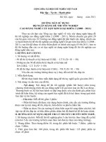
2.3
Mounting
CAUTION
Installation Precautions
The controller can be mounted on either a vertical or tilted panel using the mounting
bracket supplied. Adequate access space must be available at the back of the panel for
installation and servicing activities.
Failure to comply with these instructions may result in product damage.
1 - Put the mounting bracket in the rail on
the top & bottom of the case.
2 - Bend the grip of the bracket & slide
the bracket along the rail until the case
is secured against the panel.
3 - Put the grip of the bracket on the
groove to fasten the case to the panel.
Side View
2.4
External Dimension
2.4.1
DC1010
DC1010/1020/1030/1040 Product Manual
4
2.4.2
DC1020
2.4.3
DC1030
2.4.4
DC1040
DC1010/1020/1030/1040 Product Manual
5
2.5
Wiring Diagrams
WARNING
Electrical Consideration / Precautions
The controller is considered “rack and panel mounted equipment” per EN61010-1, Safety
Requirements for Electrical Equipment for Measurement, Control and Laboratory Use, Part 1:
General Requirements. Conformity with 72/23/EEC Low Voltage Directive, requires the user to
provide adequate protection against a shock hazard. The user shall install this controller in an
enclosure that prevents OPERATOR access to the rear terminals.
Failure to comply with these instructions could result in death or serious injury.
CAUTION
Applying 85-264Vac to a controller rated for 15-50Vdc will severely damage the controller
and is a fire and smoke hazard.
Failure to comply with these instructions may result in product damage.
CAUTION
Wiring Requirements
Shielded twisted pair cable is required for all Analog I/O, Process Variable, RTD, Thermocouple, dc
millivolt, low level signal, mA, Digital Output, and computer interface circuits.
Failure to comply with these instructions may result in product damage.
CAUTION
Line Voltage Wiring
This controller is suitable for connection to 90-240 Vac, 50/60 Hz or 15-50 Vdc, power supply
mains. It is the user responsibility to provide the following
90-240 Vac - a switch, fuse (1/2A, 250V) or a circuit breaker.
15-50 Vdc – a switch, fuse (1A, 125A) or a circuit breaker
Fuse types – North America non-time delay, Europe – Type F, quick acting fuse(s).
The above items should be installed together with DC1000 for the products electrical protection.
The switch or circuit-breaker should be located close to the controller, within easy reach of the
operator. The switch or circuit-breaker should be marked as the disconnecting device for the
controller.
When applying power to multiple instruments, make sure that sufficient current is supplied.
Otherwise, the instruments may not start up normally due to the voltage drop caused by the inrush current.
Failure to comply with these instructions may result in product damage.
DC1010/1020/1030/1040 Product Manual
6
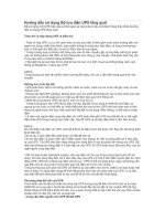
2.5.1 DC1010
N
Noise
Filter
POWER
1
L
2
AC 90 ~ 240V
(50 / 60Hz)
4
10
PV
Relay Volt
2
9
14
OUTPUT
1
8
13
5
OUT2
7
12
3
DC 15 ~ 50V
(option)
6
11
2
3
Linear
3
A,B,C,D
Linear
OUT1=5
7
11 G1
Relay Volt
4
1
2
Linear
3
B
8
12 K1
13 G2
OUT1
RTD
14 K2
TC
7
7
8
8
9
B
9
9
10
A
10
10
ALARM
5
A,B,C,D
OUT1=7
AL1
AL1
AL2
2
11
13
3
12
14
2
AUX. OUT
TRS
3 CLOSE
11
4 OPEN
COMM.
COMM
RS232
RD
12
5 COM
SD
SG
DC1010/1020/1030/1040 Product Manual
7
11
12
13
COMM
RS485
D- 11
D+
12
13
2.5.2 DC1020
L
1
11
2
12
3
13
4
14
5
15
6
16
7
17
8
18
9
19
10
20
L inear
R TD
Noise
Filter
POW ER
N
AC 90 ~ 240V
(50 / 60Hz)
DC 15 ~ 50V
(option)
PV
OUTPUT
OUT2
6
Relay
1
Vo lt
2
Lin ear
3
17
TC
17
17
18
18
B
18
7
A, B , C, D
OUT1
Relay Vo lt
1
8 NO
2
3
9 NC
10
COM
OUT1= 7
19
B
19
19
20
A
20
20
Lin ear
ALARM
AUX. OUT
AL1
A, B , C, D
AL2
3 NC
AL3
NC 11
4 NO
NO
11
6
TRS
12
7
12
6
5
7
COM
COM
13
13
CLOSE
8 OPEN
9
10 COM
INPUT2
COMM.
COMM
RS232
RD
14
14
15
SD
16
SG 16
15
COMM
RS485
D-
D+
14
15
16
DC1010/1020/1030/1040 Product Manual
8
2.5.3 DC1030
L
Noise
Filter
POW ER
N
AC 90 ~ 240V
(50 / 60Hz)
DC 15 ~ 50V
(option)
1
15
8
2
16
9
3
17
10
4
18
11
5
19
12
6
20
13
7
21
14
PV
OUTPUT
OUT2
3
Relay
1
Vo lt
2
Lin ear
3
4
A, B , C , D
OUT1
Relay
Vo lt Linear
1
5 NO
2
3
L inear
OUT1= 5
15 G1
11
17 G2
12
COM
OUT1= 7
19
CLOSE
PROT
20
12
12
13
13
14
A
14
14
ALARM
AL1
OUT1= 8
AUX. OUT
AL2
COM
3
A, B , C , D
NO
4
TRS
8
18
9
19
10
16 K1
INPUT2
5 OPEN
17 G2
6
18 K2
7 COM
11
B
NC
4
11
13
15 G1
3
TC
B
6 NC
7
R TD
Rem o te SP
9
20
10
COM M .
COMM
RS232
RD
15
SD 16
PROT
21
SG 17
DC1010/1020/1030/1040 Product Manual
9
COMM
RS485
D-
D+
15
16
17
2.5.4 DC1040
L
Noise
Filter
POWER
N
AC 90 ~ 240V
(50 / 60Hz)
DC 15 ~ 50V
(option)
1
31
11
2
32
12
3
33
13
4
34
14
5
35
15
6
36
16
7
37
17
8
38
18
9
39
19
10
40
20
Relay Vo lt Linear
1
2
3
6
7
Relay Vo lt Linear
1
8 NO
2
3
9 NC
COM
OUT1=7
31
D-
D+
SG 33
31
32
33
AUX. OUT
TRS
39
40
L inear
31 RG
31 G1
17
33 RG
33 G2
18
35 TG1
39
37 TG2
40
TC
17
17
18
18
B
19
B
19
19
20
A
20
20
ALARM
OUT1=9
39
A, B, C, D
RTD
PROT
AL1
AL2
3 NC
31 G1
AL3
NC 11
6
40
OUT1=8
31 G1
33 G2
7 CLOSE
32 K1
34 K2
8 OPEN
33 G2
35 G3
9
34 K2
36 K3
5
NO
COM
COM
INPUT2
Rem o te SP
14
PROT
PROT
40
13
COMM.
COMM
RS232
RD
14
SD 15
16
SG 16
COMM
RS485
D-
D+
14
15
16
* Once INPUT2 and COMM. options are selected together,
the wiring terminal for COMM will be changed as above.
DC1010/1020/1030/1040 Product Manual
10
7
12
15
39
35
36
4 NO
32 K1
6
10 COM
COMM
RS485
SD 32
OUT1=5
PROT
10
RD
OUT1=6
A, B, C, D
OUT1
COMM
RS232
PV
OUTPUT
OUT2
COMM.
3.
Configuration
3.1
Operator Interface
Upper Display
Lower Display
Bar Graph
LEDs
OUT1
OUT2
AT
AL1
AL2
AL3
MAN
PRO
4 digits dedicated to display the PV. In configuration mode, this display indicates
the name of parameter.
4 digits dedicated to display the SP. In configuration mode, this display indicates
the value of parameter or the status of parameter selected.
A bargraph of 10 green LEDs’ indicates the value of the output in percentage.
Status of ‘Output 1’.
Status of ‘Output 2’.
When the LED is ON, it indicates the controller is in automatic tuning process .
Status of ‘Alarm 1’.
Status of ‘Alarm 2’.
Status of ‘Alarm 3’.
When the LED is ON, it indicates the controller is in manual mode.
When a program is running, the LED flickers.
When a program is suspended, the LED is ON.
When no program is running, the LED is OFF.
Keys
SET
A/M
SHIFT
UP
DOWN
SET key allows moving from one parameter to another or saving a new value of
parameter or a status of parameter changed.
A/M key allows switching from automatic mode to manual mode or from manual
mode to automatic mode.
SHIFT key allows shifting the digits to modify parameters.
UP key allows increasing the value of a digit selected or changing the status of
parameter.
DOWN key allows decreasing the value of a digit selected or changing the status
of parameter.
Upper Display
Lower Display
LEDs
Bar Graph
SHIFT key
0%
20
40
60
80
100%
SET key
Up key
A/M key
Down key
DC1010/1020/1030/1040 Product Manual
11
3.2
MODE Access
Operation
(1)
Configuration 1
(2)
(3)
Program
(2)
Configuration 2
(3)
Set Up
How to move from one MODE to another
(1)
Press ‘SET’ key for 5 seconds; it grants access to ‘Configuration 1’ mode or return to
‘Operation’ mode from ‘Configuration 1’ mode.
(2)
Press ‘SHIFT’ key for 5 seconds while pressing ‘SET’ key first; it grants access to
‘Configuration 2’ mode or return to ‘Operation’ mode.
(3)
All parameters related to program configuration will be displayed next to parameters in
‘Operation’ mode. (* These parameters will be shown in program model only)
NOTICE
DO NOT access ‘Set Up’ mode without instruction from technical assistant.
DC1010/1020/1030/1040 Product Manual
12
3.3
MODEs
3.3.1
Operation
Parameter
Description
PV Display
SP Display
SET
Output Limit
To limit the Maximum of Control Ouput
Percentage (%)
SET
Auto Tuning
Status
* Default ‘No’
Alarm 1
Enter deviation value or absolute value
Value of alarm setpoint
Depending on alarm mode selected
SET
SET
Alarm 2
The same with Alarm1
SET
Alarm 3
The same with Alarm 1
* The ‘OUTL’ is not shown in default mode.
* ‘AL2’ & ‘AL3’ are shown only in the model the relevant options are taken.
DC1010/1020/1030/1040 Product Manual
13
3.3.2
Configuration 1
‘Configuration 1’ will be shown by pressing ‘SET’ key for 5 seconds in ‘Operation’ mode.
Parameter
SET
SET
Description
Main Control (OUT1)
Range: 0~200%
P value (Proportional Band)
P1=0, ON/OFF Control
Main Control (OUT1)
Range: 0~3600 seconds
I value (Integral Time)
I=0, Integral off
Main Control (OUT1)
Range: 0~900 seconds
D value (Derivative Time)
D=0, Derivative off
Main Control
* DO NOT CHANGE THE VALUE
SET
Dead-Band Time
SET
Main Control (OUT1)
Range: 0~ Upper limit value (USPL)
‘Auto tuning’ offset
Prevent from ‘Overshoot’ during auto tuning
SET
Main Control (OUT1)
Output type (SSR
Cycle of Control Output
Range: 0~150 seconds
Main Control (OUT1)
Actuation of Hystersis
Just in case of ON/OFF control (P1=0) (Range: 0~1000)
ON
: PV<=(SP-HYS1)
OFF : PV > (SP+HYS1)
Sub Control (OUT2)
The same with the method of P1 configuration
1, 4~20mA 0, relay 10)
SET
SET
P value (Proportional band)
SET
The same with the method of I1 configuration
Sub Control (OUT2)
I value (Integral Time)
SET
The same with the method of D1 configuration
Sub Control (OUT2)
D value (Derivative Time)
SET
The same with the method of CYT1 configuration
Sub Control (OUT2)
Cycle of Control Output
SET
The same with the method of HYS1 configuration
Sub Control (OUT2)
Hysteresis
SET
Main Control (OUT 1)
Control ouput is turned off before getting to SP
Gap
Turning Point = SP-GAP1; OFF (OUT1=Heat)
Sub Control (OUT2)
Control Output to be turned on before getting to SP
SET
Gap
Turning Point = SP+GAP2; ON (OUT2=Cool)
Function Lock
* Refer to ‘2.3 Function Lock’ in P.10
SET
SET
* The parameters are only for ‘Output’ 2 function, so it will appear only in the model which has the “OUT2” option.
DC1010/1020/1030/1040 Product Manual
14
3.3.3
Configuration 2
‘Configuration 2’ mode will be shown by pressing ‘SHIFT’ key for 5 seconds WHILE pressing ‘SET’ key
FIRST in ‘Operation’ or ‘Configuration 2’ mode.
Parameter
Description
To define input type & input range
Input 1 (INP1)
* Refer to
SET
SET
Input 1 (INP1)
To be used during the calibration for linear input
Lower limit of linear Input
* DO NOT change this value without technical support
Input 1 (INP1)
To be used during the calibration for linear input
Upper limit of linear Input
* DO NOT change this value without technical support
Decimal Point
Available in linear input only
Lower limit of Input range
i.e) Linear input = 4~20mA,
SET
SET
when 4mA (0%), set the indication value for lower limit
SET
when 20mA (100%), set the indication value for upper limit
Upper limit of Input range
SET
Input 2 (INP2)
To be used during the calibration for linear input
Lower limit of linear input
* DO NOT change this value without technical support
Input 2 (INP2)
To be used during the calibration for linear input
Upper limit of linear input
* DO NOT change this value without technical support
Alarm Code of ‘Alarm 1’
* Refer to
SET
SET
SET
Time Set for ‘Alarm 1’
* Range: 0 - 99 min 59 sec
0= flickering alarm, 99.59= continuant alarm
SET
Others = Time delay of alarm
Alarm Code of ‘Alarm2’
SET
The same configuration method with ALT1
Time Set for ‘Alarm 2’
SET
Alarm Code of ‘Alarm 3’
SET
Time Set for ‘Alarm 3’
The same configuration method with ALT1
Hysteresis of alarms
To set the hysteresis of alarm actuation (Range: 0 – 1000)
ON
: PV<=(SP-HYS1)
OFF : PV > (SP+HYS1)
SET
SET
DC1010/1020/1030/1040 Product Manual
15
Parameter
Description
Main Control (OUT1)
To adjust the linear control output during the calibration
Lower limit of linear output
* DO NOT change the value without technical support
Main Control (OUT1)
To adjust the linear control output during calibration
Upper limit of linear output
* DO NOT change the value without technical support
Sub Control (OUT2)
The same configuration method with ‘CL01’
SET
SET
Lower limit of linear output
SET
Sub Control (OUT2)
The same configuration method with ‘CH01’
Upper limit of linear output
SET
Aux. Output
Lower limit of linear output
The same configuration method with ‘CL01’
Aux. Output
The same configuration method with ‘CH01’
SET
Upper limit of linear output
SET
Full actuation time of Time proportional motor control
Timer for Motor Control
Range: 5 – 200 sec
SET
To set ‘wait’ for program operation
WAIT function
0= No wait, others = Wait volume
SET
Extra SET
DO NOT change the value of this parameter
ID Number
Communication ID number
Baud Rate
DO NOT change the value of this parameter
SP compensation
Range: -1000~1000
PV compensation
Range: LSPL~USPL
Unit of PV & SP
Selection: C, F, and A (linear)
Soft Filter
To adjust PV response time (Range: 0.05 – 1.00)
SET
SET
SET
SET
SET
SET
* The bigger value gives the faster response.
SET
* Those 2 parameters are only for adjusting the linear signal of control output, not for the limitation of the control output
or any other purpose. Please, DO NOT change the values without Technical Support, see Contacts page.
DC1010/1020/1030/1040 Product Manual
16
Parameter
Description
* DO NOT change the value
SET
Operation Mode
Heating (direct) or Cooling (reverse)
Control Process
PID or Fuzzy
Frequency
50 or 60Hz
SET
SET
* Please, check whether the proper frequency is selected
SET
3.4
Alarms
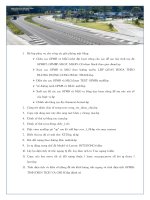
3.4.1
Deviation Alarm
The Alarm SP (Set Point) is to be changed as the SP moves. In this case, the Alarm SP preserves a
certain deviation value with the SP. When an alarm is set, a certain deviation value with the preset SP
should be defined.
Alarm SP moves along SP change
Deviation
(Lower limit)
SP1
SP1
SP2
SP Change
Alarm SP
Alarm SP moves along SP change
Deviation
(Upper Limit)
SP1
SP1
Alarm SP
SP2
SP Change
3.4.1.1 Upper Limit Deviation Alarm (Alarm Code 01, Alarm release in the first alarming situation)
: Set Point
: Alarm Set Point
3.4.1.2 Upper Limit Deviation Alarm (Alarm Code 11, No alarm release in the first alarming situation)
DC1010/1020/1030/1040 Product Manual
17
3.4.1.3 Lower Limit Deviation Alarm (Alarm Code 02, Alarm release in the first alarming situation)
3.4.1.4 Lower Limit Deviation Alarm (Alarm Code 12, No alarm release in the first alarming situation)
3.4.1.5 Dev. Band Breakaway Alarm(Alarm Code 03, Alarm release in the first alarming situation)
3.4.1.6 Dev. Band Breakaway Alarm(Alarm Code 13, No alarm release in the first alarming situation)
3.4.1.7 Deviation Band Alarm (Alarm Code 04, Alarm release in the first alarming situation)
3.4.1.8 Deviation Band Alarm (Alarm Code 14, No alarm release in the first alarming situation)
3.4.2
Absolute Value Alarm
The Alarm SP (Set Point) is to be fixed even though the SP moves. When an alarm is set, the absolute
value of the Alarm SP should be defined.
Alarm Set Point (Fixed)
SP1
SP2
SP3
3.4.2.1 Absolute Upper Limit Alarm (Alarm Code 05, Alarm release in the first alarming situation)
3.4.2.2 Absolute Upper Limit Alarm (Alarm Code 15, No alarm release in the first alarming situation)
DC1010/1020/1030/1040 Product Manual
18
3.4.2.3 Absolute Lower Limit Alarm (Alarm Code 06, Alarm release in the first alarming situation)
3.4.2.4 Absolute Lower Limit Alarm (Alarm Code 16, No alarm release in the first alarming situation)
3.4.3
Program Alarm
3.4.3.1 Segment End Alarm (Alarm Code 07)
Once the selected segment is completed, the alarm becomes actuated
- ALD1 – ALD3
Set the Alarm Code 07
- AL1 – AL3
Enter Segment No. for alarms
- ALT1 – ALT3
Define the alarm timing
(0 Flickering, 99.59
Continuant, Others
Time Delay)
3.4.3.2 Program RUN Alarm (Alarm Code 17)
While a program runs, the alarm becomes actuated
3.4.4
System Alarm
3.4.4.1 System Error Alarm (Alarm Code 08)
3.4.4.2 System Error Alarm (Alarm Code 18)
3.4.4.3 Timer Alarm (Alarm Code 19)
Once the PV reaches to the SP, the alarm becomes actuated after a certain time delay.
(Range: 00 hour 00 min – 99 hour 59 min)
DC1010/1020/1030/1040 Product Manual
19