CMVA65 Microlog Data Collector/Analyzer
Bạn đang xem bản rút gọn của tài liệu. Xem và tải ngay bản đầy đủ của tài liệu tại đây (4.52 MB, 410 trang )
CMVA65 Microlog
Data Collector/Analyzer
Supports MICROLOG Firmware Version 3.92
User Manual Part No. 31963600
Revision B
User Manual
Copyright 2004 by SKF Condition Monitoring Inc.
All rights reserved
5271 Viewridge Court
San Diego, CA 92123 USA
SKF Reliability Systems
5271 Viewridge Court
San Diego, CA 92123 USA
Telephone (858) 496-3400
FAX (858) 496-3531
052104 dcs
SKF Condition Monitoring
Service Policy, Warranty, Disclaimer, and Limitation of
Remedies
EXCEPT FOR THE LIMITED WARRANTY DESCRIBED BELOW, THERE ARE NO
WARRANTIES, EXPRESSED OR IMPLIED, INCLUDING BUT NOT LIMITED TO
THE IMPLIED WARRANTIES OF MERCHANTABILITY AND FITNESS FOR A
PARTICULAR PURPOSE; ALL SUCH WARRANTIES ARE EXPRESSLY AND
SPECIFICALLY DISCLAIMED.
MICROLOG is guaranteed free of defects in material and workmanship.
Electronic components, transducers, accelerometers, and the keypad are guaranteed for a
period of twelve (12) months, mechanical components and cable assemblies are
guaranteed for a period of ninety (90) days.
This warranty does not extend to units that have been misused, altered, or repaired
without manufacturer's authorization. Defects or failures experienced during the warranty
period will be corrected at no charge at the manufacturer's facility. If, upon examination,
it is found that the defect is not within the scope of this warranty, an estimate of repair
charges and a request for authorization to proceed with repair will be submitted, along
with a statement of the reasons the repairs are not considered to be covered by the
warranty.
This warranty does not extend to system components such as transducers, drivers, and
cable assemblies manufactured by others. Warranty for these components will be their
manufacturer's standard.
Manufacturer's liability under this warranty is limited to repair or replacement of any
defective instrument at the discretion of the manufacturer.
In the event that any of the above limitations are held unenforceable, our liability to you
shall not exceed the license fee you paid, regardless of the form of any claim. Because of
the extreme diversity of ways that the product can be used, you are advised to test the
product thoroughly for your purposes before relying on it.
Table of Contents
Introduction
About This Manual 1
Chapter Overview 1
Who Uses the Microlog/Machine Analyst
System? 2
What is the CMVA65 Microlog System? 3
The CMVA65 Microlog Data Collector 3
Machine Analyst Host Software 5
The Support Module 6
Microlog System Connections 8
What You Will Find on the Main Screen 9
Version Number 9
The Status Line 10
The Working Area 11
The Prompt Area 13
The Keypad 13
Operating Keys 14
Control 15
Keys 15
Numeric Keys 15
Function Keys 16
Miscellaneous Keys 17
The Backlighting Key 18
BNC Connectors 18
How to Initialize Your Microlog 20
Standard Microlog Measurement Setups
How to Use this “Applications” Section 2
What Is Typical Machinery? 2
What Are Standard Measurements? 3
Velocity Measurement Assumptions and
Deviations 5
Assumptions 5
Deviations 6
Standard Velocity Measurement 7
Overview 8
Setting the Microlog's Utilities Options 8
Standard Velocity Measurement Setup 10
CMVA65 Microlog Setup 10
Standard Acceleration Measurement 13
Overview 14
Standard Acceleration Measurement Setup 14
Standard Enveloped Acceleration
Measurement 17
Overview 18
Standard Enveloped Acceleration
Measurement Setup 18
Standard Displacement Measurement 21
Overview 22
Standard Displacement Measurement Setup 22
The Route Menu
Machine Analyst Software’s ROUTE Feature 1
What is a ROUTE? 1
Collecting Data 2
The Route List 3
Right and Left Arrow Keys 4
Options 5
Static Measurements 6
Measurement Options Menu (Static) 8
Dynamic Measurements 10
Route Spectrum:Show 11
Speed Tagging 12
Route Spectrum:Hide 17
Measurement Options Menu (Dynamic) 18
Using a Temporarily Attached Pickup 19
Hints for Efficient Data Collection 19
Reducing Keystrokes 19
Auto Range 20
The Probe 21
To Make An On-the-Spot Analysis 21
Spectral Banding 22
Downloading FAM Information 25
Multi-Point Automation (MPA) 28
MPA ROUTE Setup 29
MPA Group Data Collection 30
Options 32
The NonRoute Menu
Overview 1
Setup 1
Types of Measurements 3
Dynamic Measurements (Overview) 4
Input Setup 5
Spectrum Setup 10
Spectrum Setup/Measurement Type:Freq 12
Spectrum Setup/Measurement Type:Orders 17
Display Setup 19
Display Setup/Trace: Single 20
Display Setup/Trace: Dual 22
Trigger Setup (User Mode:Analysis only) 23
Marker Setup (User Mode:Analysis only) 25
HAL Setup (User Mode:Analysis only) 27
Collecting NonRoute Dynamic Data 29
Using the Function Keys 30
Marker Mode:Cursor Lock 31
Marker Mode:Fixed Freq 32
Process Measurements 36
Collecting NonRoute Process Data 38
HFD Measurements 40
Collecting NonRoute HFD Data 41
Running Speed Measurements 42
Collecting NonRoute Running Speed Data 43
The Transfer Menu
Setting the Communication Mode Parameters 1
Data Transfer 2
Data Transfer - Download 3
Modem Mode:None 3
Modem Mode:Originate 6
Modem Mode:Auto Answer 6
Data Transfer - Upload 6
User Notes 8
The Applications Menu
Balancing (Basic) 2
Basic Balancing Tips 12
Balancing (Advanced) 13
Overview 13
Single Plane Balancing 14
Two Plane Balancing 16
Setting Balancing (Advanced) Options 16
Reference Run 24
Trial Run 25
Estimate Trial Weight Setup 26
Trial Weight Setup 28
Trial Run 30
Correction Weight 31
Correction Weight Run 32
Splitting One Weight Into Two 32
Setup 32
Trim Run 34
The Review/Enter Data Screens 38
Correction Weight 40
View Run Data 40
The Influence Coeff Screen 41
Save Balance Job 42
The Utility Functions Menu 43
Combining Weights 43
Setup 43
Calculations 45
Splitting One Weight Into Two 45
Setup 45
Calculations 47
Balance Job Reports 47
Clearing the Current Job From Temporary
Memory (RAM) 49
Reset Setup 50
Delete Job 50
Advanced Balancing Tips 50
Tracking Filter 54
Cyclic Analysis 57
Current Analysis Setup 62
Current Analysis Data Collection 70
Current Zoom 70
Enveloped Current 73
Bump Test 74
Why Do a Bump Test? 75
Run Up/Coast Down 78
Take Data 80
Setup 87
Review Data 91
Print Table Report 96
Print Graph Report 98
Configuration Wizard 99
User Notes 104
The Analyzer Menu
The Analyzer Function 1
Setup 1
Collecting Dynamic Data 3
Using the Function Keys 4
Marker Mode:Cursor Lock 4
Marker Mode:Fixed Freq 5
Phase Measurements 6
User Notes 8
The Review Menu
How To Use the Review Function 1
The Reports Menu
The Reports Menu 1
The Report Controls Menu 3
F1 - Route List/F2 - Print 5
Sample Report Formats 6
Exceptions Report 6
End of Shift Report 8
Missed Points Report 10
Dynamic Points Report 11
Dynamic Points Report Including Spectral
Banding Information 14
Dynamic Points Report Including
Phase Spectrum 16
Dynamic Points Report Including FAM Data
Summary 17
Database Setup Report 18
The Notes Report 20
Print Test 21
User Notes 22
The Utilities Menu
Display Setup 1
Temp/Battery 6
Set Clock 7
Communications 9
System Setup 11
Route Setup 18
Memory Test 23
Recover 23
Initialize 24
Flash Utilities 26
Battery Capacity, Care, and Testing
Changing Batteries 1
Battery Life 2
Battery Charging 2
Unintentional Discharge 5
Aborting Deep Discharge 5
Thermal Switch - NiMH Battery Pack 5
Specifications
Specifications for CMVA65 1
Why Zoom?
Multi-pin Input Pinouts
Pinout Diagram 1
Model CMVA65 RS232 D Connector Pinout 1
Remote Communications
Overview 1
Preference Settings (PRISM
4
Remote) 1
System Preferences 2
Communication Preferences 3
Placing PRISM
4
Remote in "Waiting" Mode 8
Preference Settings (Microlog) 9
Baud 10
Modem Mode 10
Microlog Remote 10
Phone # 10
Microlog Login (Remote Communication
Module) 11
Send Data 15
Load Route 17
Change DBase 19
Clear Memory 21
Reset DBase 22
Disconnect 24
Supported Modems 24
Troubleshooting Modem Communications 25
User Notes 28
Microlog Download Utility
Installing Microlog Download Utility 1
Connecting your Microlog 1
Microlog Setup 2
Downloading Code/Fonts 3
Introduction to the Triax Accelerometer
Sensor
Overview 1
How to Mount the Triax Accelerometer Sensor 1
Permanent Mount with Screw 2
Studs and Adapter 3
Magnet Mounting Base 5
Triaxial MPA ROUTE Setup 6
Connecting the Triaxial Sensor to the Microlog7
Hardware Requirements 7
Triaxial MPA Group Data Collection 7
Options 10
The Harmonic Activity Location (HAL)
Feature
Overview 1
How to Use HAL on the CMVA65 Microlog 3
Using HAL on ROUTE POINTs Downloaded
with FAM Data 4
HAL Alarm Notification – MPA POINTs 11
Applying HAL to Non-ROUTE POINTs 12
Applying HAL to Analyzer POINTs 15
Reviewing HAL Results 15
User Notes 18
Glossary
Index
CMVA65 Microlog Intro - 1
User Manual
I
Introduction
About This Manual
This manual introduces you to the CMVA65 Microlog
system. It offers a complete and detailed reference to each
Microlog menu, data screen, and data screen option. This
information is essential when setting up the CMVA65
Microlog and when using the Microlog to collect and
display machinery data.
As you use this manual, you'll discover certain conventions
used:
Bold type is used to indicate text that appears in a
Microlog menu or data screen. Italics are used to
emphasize important information.
- are used to indicate notes to the reader.
Step-by-step procedures are sequenced using bullets,
•.
The CMVA65 Microlog may be
configured for either English or Metric
units of measurement. In this manual, all
Microlog setup and display screens
appear with English units.
Chapter Overview
This manual's chapters are organized to help the new
Microlog user quickly set up the Microlog for measuring
specific applications, and to quickly reference the
Microlog's menus, data screens, and options. A chapter
overview follows:
Introduction
Who Uses the Microlog/Machine Analyst System?
Intro - 2 CMVA65 Microlog
User Manual
Introduction - Describes this User Manual,
overviews the Microlog system, and describes new
enhancements to the Microlog data collector.
Applications - This section uses flow charts and text
to help new users quickly set up the Microlog to
perform “standard” vibration measurements on
“typical” rotating machinery.
Reference Manual - Chapters 1 - 8
Chapters 1 through 8 offer a complete and detailed
description of each Microlog menu, its data screens and
options:
Chapter 1, The Route Menu
Chapter 2, The NonRoute Menu
Chapter 3, The Transfer Menu
Chapter 4, The Applications Menu
Chapter 5, The Analyzer Menu
Chapter 6, The Review Menu
Chapter 7, The Reports Menu
Chapter 8, The Utilities Menu
Appendices A - H
Appendices A through H provide valuable information on
the Microlog and its applications:
Appendix A, Battery Capacity, Care, and Testing
Appendix B, Specifications
Appendix C, Why Zoom?
Appendix D, Multi-pin Input Pinouts
Appendix E, Remote Communications
Appendix F, Microlog Download Utility
Appendix G, Intro to the Triax Sensor
Appendix H, Harmonic Activity Locator (HAL)
Who Uses the Microlog/Machine Analyst System?
The CMVA65 Microlog/Machine Analyst System is used
by experienced machinery maintenance personnel who wish
Introduction
What is the CMVA65 Microlog System?
CMVA65 Microlog Intro - 3
User Manual
to collect and analyze vibration data from their rotating
machinery, to help reduce costs and downtime.
What is the CMVA65 Microlog System?
A CMVA65 Microlog System (Figure I - 1) consists of
three components:
• A CMVA65 Microlog data collector,
• A host computer with Machine Analyst, or equivalent
software, and
• A support module.
Figure I - 1.
The Microlog System.
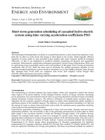
The CMVA65 Microlog Data Collector
The CMVA65 Microlog data collector is a lightweight,
portable, data acquisition and storage terminal (Figure I-2).
It collects machinery vibration, temperature, and other
condition monitoring measurements. Together with visual
observations, the CMVA65 Microlog allows for detailed
CMSS50080 or
CMSS50080-CE and
CMSS250 25 PIN to 9 Pin
host computer Microlog
data collector
CMSS50077
support module
Introduction
What is the CMVA65 Microlog System?
Intro - 4 CMVA65 Microlog
User Manual
machine condition analyses in a harsh industrial
environment.
Figure I - 2.
Model CMVA65.
The Microlog performs all the tasks required for machinery
predictive (condition) maintenance. It automatically
collects both dynamic (vibration) and static (process)
measurements from almost any source, it provides easy to
use set up screens for quickly capturing data related to
specific applications like balancing, tracking filter, cyclic
analysis, and current analysis, and it allows the user to
configure up to 12 measurements for automatic data
collection at one measurement point. Using the same
sensor, the user need press only one button to sequentially
collect all pre-configured measurements.
A variety of input devices may be used with your Microlog.
Vibration measurements are collected with a handheld
probe, magnetically mounted probe, permanently mounted
sensors, or from an installed monitoring system.
Introduction
What is the CMVA65 Microlog System?
CMVA65 Microlog Intro - 5
User Manual
Temperature measurements are collected with a non-contact
infrared sensor or with a contact probe.
Values read from other indicators may be entered into the
Microlog by pressing the appropriate numeric keys on the
Microlog keyboard. You can also enter your observations
by typing them in languages or as coded notes.
In addition to its function as a data collector, the Microlog
has all the functions and performances of a powerful
analyzer to capture and display high resolution spectra for
detailed analysis. A Fast Fourier Transform (FFT)
frequency spectrum and a time domain waveform are
available for display on the LCD (Liquid Crystal Display)
screen.
The Microlog automatically turns itself off after 5 minutes
of inactivity to preserve battery life (in all functions except
Analyzer, Transfer, Battery/Temperature, and Reports).
Machine Analyst Host Software
Machine Analyst is an optional support software package
that works with the Microlog to help machinery
maintenance personnel manage machine condition data.
The Machine Analyst host software automatically performs
the tedious clerical work required in sorting and saving
data. Through detailed printed reports, it alerts
maintenance personnel to alarm conditions (exceptions
from normal).
Introduction
What is the CMVA65 Microlog System?
Intro - 6 CMVA65 Microlog
User Manual
Machine Analyst software helps machinery maintenance
personnel to understand the true condition of their rotating
machinery and to base maintenance decisions on the actual
condition of machines.
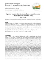
Machine Analyst software excels in presenting collected
machinery data in statistical and graphic plot format to
obtain useful analysis data (Figure I - 3).
Figure I - 3.
A Machine Analyst Spectrum Display.
Refer to the Machine Analyst software's User Manual for
operational details.
The host computer has varying minimum
configurations depending on which
Machine Analyst software is used. See
your Machine Analyst software's User
Manual for detailed minimum
configuration information.
The Support Module
The CMVA6112 Support Module (Figure I - 4) is capable
of fast charging the NiMH (CMVA50230-1) battery pack.
Introduction
What is the CMVA65 Microlog System?
CMVA65 Microlog Intro - 7
User Manual
Figure I - 4.
The CMVA6112 Support Module.
There are 2 LEDs and a Deep Discharge button on the
CMVA6112 Support Module. The Deep Discharge button
is used for deep discharging the battery pack in the support
module's pocket. Once deep discharging is complete, the
support module automatically fast charges the battery pack.
The “Battery in Charger” LED indicates the charging
status of the battery pack on the support module, the
“Battery in Microlog” LED displays the charging status of
the battery pack in the Microlog.
The LEDs indicate the battery pack's 3 different charging
modes:
Deep Discharging (Support Module battery only) -
LED flashes slowly.
Fast Charge - LED is ON continuously.
Trickle Charge - LED flashes quickly.
Reference Appendix A for a detailed
description of battery capacity, care, and
testing.
The CMVA6112 is powered by an
universal AC/DC adapter. Use of a
Introduction
Microlog System Connections
Intro - 8 CMVA65 Microlog
User Manual
different adapter to power the Support
Module should be consulted with the
manufacturer, or the Support Module may
be damaged.
Microlog System Connections
The support module (Figure I - 4) supplied with each
Microlog system provides a convenient, compatible
interface between the Microlog and its host computer
through RS-232 connectors. The support module also
contains the battery charger for the Microlog's batteries.
To connect your Microlog system:
• Using the supplied CMSS50080, CMSS50080-CE
cable, or CMSS250 (25 PIN to 9 PIN adapter
supporting 9 PIN serial ports), connect your host
computer to the support module between the
connection marked COMPUTER on the support
module and one of the serial ports (COM1 or COM2)
on the back of your computer (Figure I - 1).
• Using the supplied CMSS50077 cable, connect the
support module to the Microlog between the connector
marked MICROLOG on the support module and the
25-pin D connector on the top surface of the Microlog
Collector.
• Plug the support module into an AC power supply
through the external transformer adapter supplied with
the support module.
Before using your Microlog, check to
make sure that the transformer adapter
supplied with your support module is
correct for your electric line supply. The
Microlog uses the same 25-pin D
connector for connection to its various
sensors and to its support module. Keep
Introduction
What You Will Find on the Main Screen
CMVA65 Microlog Intro - 9
User Manual
the connector attached to insure it remains
clean while in an industrial environment.
What You Will Find on the Main Screen
The Microlog collector has a large, supertwist graphic color
liquid crystal display (LCD). Everything needed to identify
and assess a measurement (identification, description,
engineering units, warning alarms, last value recorded, and
current value) appears on the color LCD screen.
When you first turn on the Microlog collector, the main
menu and title block are displayed (Figure I - 5).
Figure I - 5.
The CMVA65 Microlog Power Up Screen.
Version Number
The title block, displayed to the right of the main menu on
power up, includes the firmware version number. Use this
number if you call customer support.
If you call customer support, you will also
be asked for the Microlog's serial number.
Introduction
What You Will Find on the Main Screen
Intro - 10 CMVA65 Microlog
User Manual
It is located on back of the Microlog
case
The Microlog screen contains three main areas: status line,
working area, and prompt area.
The Status Line
The one-line strip at the top of your Microlog screen is
called the status line (Figure I - 6).
Figure I - 6.
The Status Line.
The status line displays the current date and time (if you
previously set them correctly). The status line also
constantly reports on the percent of free memory available.
Other items of information appear from time to time in the
status line. They are:
• Signal Overload Warning (OV)
• Low Battery Warning (BT)
• Out of Limit Collector Temperature Warning
(TP)
• Shift Lock On up arrow indicator
When the BT (low battery charge) indicator appears, you
have approximately 20 minutes to complete immediate
measurements before the Microlog shuts down to preserve
your data. At this point you can replace the main Error!
Reference source not found.battery or connect the
Microlog to its support module charger. All data and
instructions in the Microlog are fully preserved for up to 3
minutes by an internal power source while you change the
main battery.
The Error! Reference source not found.Signal Overload
Warning (OV) displays to warn of probable inaccuracies
status line
Introduction
What You Will Find on the Main Screen
CMVA65 Microlog Intro - 11
User Manual
when an incoming signal overloads the internal signal
conditioning. Do not record data with the OV indicator
continuously on. Instead, range up by pressing the up
arrow key until the OV warning disappears.
The Working Area
The Microlog's working area includes all screen lines
except the top line (the status line), and the bottom line (the
prompt line).
Figure I - 7.
The Main Menu.
The working area displays various menus (Figures 1 - 7 and
1 - 8), Error! Reference source not found.vibration
spectra (Figure 1 - 9), and machinery condition displays
(Figure 1 - 10).