MICROLOGIC® 3.0A, 5.0A and 6.0AElectronic Trip Units
Bạn đang xem bản rút gọn của tài liệu. Xem và tải ngay bản đầy đủ của tài liệu tại đây (943.62 KB, 33 trang )
48049-136-02
4/01
Cedar Rapids, IA, USA
Instruction Bulletin
Retain for future use.
English
K849
MICROLOGIC
®
3.0A, 5.0A and 6.0A
Electronic Trip Units
The addition of either symbol to a “Danger” or “Warning” safety label indicates that an electrical hazard
exists which will result in personal injury if the instructions are not followed.
This is the safety alert symbol. It is used to alert you to potential personal injury hazards. Obey all safety
messages that follow this symbol to avoid possible injury or death.
NOTE: Provides additional information to clarify or simplify a procedure.
Electrical equipment should be installed, operated, serviced and maintained by qualified electrical
personnel. This document is not intended as an instruction manual for untrained persons.
This equipment has been tested and found to comply with the limits for a Class A digital device, pursuant
to part 15 of the FCC Rules. These limits are designed to provide reasonable protection against harmful
interference when the equipment is operated in a commercial environment. This equipment generates,
uses, and can radiate radio frequency energy and, if not installed and used in accordance with the
instruction manual, may cause harmful interference to radio communications. Operation of this
equipment in a residential area is likely to cause harmful interference in which case the user will be
required to correct the interference at his own expense.
DANGER
!
DANGER indicates an imminently hazardous situation which, if not
avoided, will result in death or serious injury.
WARNING
!
WARNING indicates a potentially hazardous situation which, if not
avoided, can result in death or serious injury.
CAUTION
!
CAUTION indicates a potentially hazardous situation which, if not
avoided, can result in minor or moderate injury.
hazardous situation which, if not avoided, can result in property damage.
CAUTION, used without the safety alert symbol, indicates a potentially
CAUTION
NOTICE
Read these instructions carefully and look at the equipment to become familiar with the device before trying to install, operate,
service or maintain it. The following special messages may appear throughout this bulletin or on the equipment to warn of potential
hazards or to call attention to information that clarifies or simplifies a procedure.
!
English
PLEASE NOTE:
FCC NOTICE:
5
© 1999–2001 Schneider Electric All Rights Reserved
Bulletin No. 48049-136-02 MICROLOGIC
®
3.0A, 5.0A and 6.0A Electronic Trip Units
4/01 Table of Contents
English
Section 1—General Information 7
Introduction 7
Communications 7
Trip Unit Settings 7
MICROLOGIC 3.0A Trip Unit 8
MICROLOGIC 5.0A Trip Unit 8
MICROLOGIC 6.0A Trip Unit 9
Zone-selective Interlocking 9
Trip Unit Switches 10
Long-time Protection 10
Short-time Protection 11
Instantaneous Protection 12
Ground-fault Protection for Equipment 12
Indicator Lights 13
Overload Indicator Light 13
Trip Indicator Lights 13
Self-protection Indicator Light 13
Ammeter 13
Trip Unit Testing 14
External Power Supply 14
Section 2—Ammeter 15
Display 15
Access Information 15
Current Menu 16
Peak Menu 17
Switch Settings Menu 18
Communication Module Screens 19
Section 3—Operation 20
Adjust Switch Settings 20
Examples 20
MICROLOGIC 3.0A Trip Unit 20
MICROLOGIC 5.0A Trip Unit 21
MICROLOGIC 6.0A Trip Unit 22
Zone-selective Interlocking (ZSI) 23
Set Communication Module values 24
Check Trip Unit Settings 26
Verify Trip Unit Operation 26
Test Equipment Ground-fault Trip Functions 27
Reset Trip Unit After Trip 27
Check Trip Unit Status 27
Section 4—Trip Unit Replacement 28
Disconnect Circuit Breaker 28
Remove Circuit Breaker Accessory Cover 28
Install Battery 28
Replace Trip Unit 28
Replace Circuit Breaker Accessory Cover 28
Test Trip Unit Installation 29
Reconnect Circuit Breaker 29
Section 5—Adjustable Rating Plug Replacement 30
Section 6—Battery Replacement 31
Disconnect Circuit Breaker 31
Remove Circuit Breaker Accessory Cover 31
Shift Circuit Breaker Withstand Module (R-frame and
NS1600b–NS3200 Circuit Breakers Only) 31
Replace Battery 31
Replace Circuit Breaker Withstand Module (R-frame and
NS1600b–NS3200 Circuit Breakers Only) 32
Table of Contents
© 1999–2001 Schneider Electric All Rights Reserved
6
MICROLOGIC
®
3.0A, 5.0A and 6.0A Electronic Trip Units Bulletin No. 48049-136-02
Table of Contents 4/01
English
Replace Circuit Breaker Accessory Cover 32
Reconnect Circuit Breaker 32
Appendix A—Register List 33
7
© 1999–2001 Schneider Electric All Rights Reserved
Bulletin No. 48049-136-02 MICROLOGIC
®
3.0A, 5.0A and 6.0A Electronic Trip Units
4/01 Section 1—General Information
English
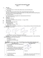
Figure 1: MICROLOGIC Trip Unit
r
e
s
e
t
A
p
I
g
I
Ð
n
I
s
d
I
i
I
r
M
i
c
r
o
l
o
g
i
c
7
0
Re
s
et
.4
.5
.6
.7
.8
.9
.95
.98
1
.5
1
2
4
8
12
16
20
24
l
o
n
g
t
i
m
e
a
l
a
r
m
Ir tr
(
s
)
x In
@
6
I
r
Micrologic 7.0 A
40
100
%
%
m
e
n
u
06134858
A
06133224
B
E
C
A—MICROLOGIC Trip Unit
B—Product Name
C—Battery Housing
D—Switch Cover
E—Switch Cover Opening Slot
F—Adjustable Rating Plug
D
F
G
H
G—Reset Button for Battery
Status Check and Trip Indicators
H—External Terminal Block Connection
06133249
Section 1—General
Information
INTRODUCTION
MICROLOGIC
®
trip units (A) provide adjustable
tripping functions on electronic trip circuit
breakers. The product name (B) specifies the
level of protection provided by the trip unit.
MICROLOGIC trip units are field replaceable to
allow for upgrading of the trip unit in the field. For
complete information on available circuit breaker
models, frame sizes, interrupting ratings, sensor
plugs, rating plugs and trip units, see the product
catalog.
COMMUNICATIONS
MICROLOGIC trip units can communicate with
other devices if the optional Breaker
Communication Module (BCM) is installed. For
information on the communication module, see
the product catalog.
TRIP UNIT SETTINGS
On the face of the trip unit are adjustable switches
to allow changing of the trip characteristics of the
trip unit. Trip units are shipped with the long-time
pickup switch set at 1.0 and all other trip unit
adjustments set at their lowest settings.
MICROLOGIC 3.0A
Type of protection
3—Basic protection (LI)
5—Selective protection (LSI)
6—Selective protection plus ground fault
Trip unit series
0—Indicates the first version
Type of measurement
None—Provides protection only
A—Provides protection plus ammeter measurements
protection for equipment (LSIG)
© 1999–2001 Schneider Electric All Rights Reserved
8
MICROLOGIC
®
3.0A, 5.0A and 6.0A Electronic Trip Unit Bulletin No. 48049-136-02
Section 1—General Information 4/01
English
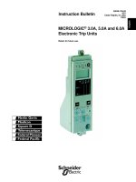
Figure 2: Settings and Trip Curve for 3.0A Trip Unit
Figure 3: Settings and Trip Curve for 5.0A Trip Unit
Micrologic 3.0 A
menu
delay
short time
tsd
instantaneous
long time
alarm
test
800
earth leakage
1
2
3
5
7
10
20
30
ÐI
60
.5
140
230
350
IÐn
setting
2.5
3
4
5
6
1.5
2.5
3
4
5
6
1.5
.5
1
2
4
8
12
16
20
tr
(s)
@ 6 Ir
24
.4
.5
.6
.7
.8
.9
.95
.98
1
Ir
x In
instantaneous
long time
alarm
.4
.5
.6
.7
.8
.9
.95
.98
1
Ir
x In
.5
1
2
4
8
12
16
20
tr
(s)
@ 6 Ir
24
x In
2
3
4
5
6
8
10
121.5
setting
Ii
0 Ir Ii I
t
06133243
A
H
I
G
E
J
06133201
G
H
I
M
N
B
C
D
L
F
K
Micrologic 5.0 A
menu
delay
short time
tsd
instantaneous
long time
alarm
test
800
earth leakage
1
2
3
5
7
10
20
30
ÐI
60
.5
140
230
350
IÐn
setting
2.5
3
4
5
6
1.5
2.5
3
4
5
6
1.5
.5
1
2
4
8
12
16
20
tr
(s)
@ 6 Ir
24
.4
.5
.6
.7
.8
.9
.95
.98
1
Ir
x In
.95
.98
setting delay
short time
I itsd
instantaneous
long time
alarm
.4
.5
.6
.7
.8
.9
1
Ir
x In
.5
1
2
4
8
12
16
20
tr
(s)
@ 6 Ir
24
x Ir
2
2.5
3
4
5
6
8
10
Isd
1.5
on
I
2
t
.
2
.
3
.
4
.
4
.
1
.
2
.
3
.
1
0
x In
3
4
6
8
10
12
15
off
2
1
2
3
4
5
0
Ir Isd I
t
Ii
06133244
A
H
I
G
E
L
06133202
O
P
B
C
D
N
F
M
J
K
G
H
I
J
K
MICROLOGIC 3.0A Trip Unit
The MICROLOGIC 3.0A trip unit provides basic
(LI) protection and a built-in ammeter.
A—Trip unit name
B—Reset button for battery status check and trip indicator LED
C—Alphanumeric display
D—Ammeter and three-phase bar graph
Navigation
E—Scroll button
F—Menu button
Switches
G—Long-time pickup (Ir) switch
H—Long-time delay (tr) switch
I—Instantaneous pickup (Ii) switch
Te s t
J—Test plug
Indicator Lights
K—Overload indicator light
L—Self-protection indicator light
M—Short-time delay or instantaneous trip indicator light
N—Long-time delay trip indicator light
MICROLOGIC 5.0A Trip Unit
The MICROLOGIC 5.0A trip unit provides
selective (LSI) protection and a built-in ammeter.
A—Trip unit name
B—Reset button for battery status check and trip indicator LED
C—Alphanumeric display
D—Ammeter and three-phase bar graph
Navigation
E—Scroll button
F—Menu button
Switches
G—Long-time pickup (Ir) switch
H—Long-time delay (tr) switch
I—Short-time pickup (Isd) switch
J—Short-time delay (tsd) switch
K—Instantaneous pickup (Ii) switch
Te s t
L—Test plu g
Indicator Lights
M—Overload indicator light
N—Self-protection indicator light
O—Short-time or instantaneous trip indicator light
P—Long-time trip indicator light
9
© 1999–2001 Schneider Electric All Rights Reserved
Bulletin No. 48049-136-02 MICROLOGIC
®
3.0A, 5.0A and 6.0A Electronic Trip Units
4/01 Section 1—General Information
English
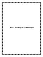
MICROLOGIC 6.0A Trip Unit
The MICROLOGIC 6.0A trip unit provides selec-
tive and ground-fault protection for equipment
(≤ 1200 A) (LSIG) and a built-in ammeter.
A—Trip unit name
B—Reset button for battery status check and trip indicator LED
C—Alphanumeric display
D—Ammeter and three-phase bar graph
Navigation
E—Scroll button
F—Menu button
Switches
G—Long-time pickup (Ir) switch
H—Long-time delay (tr) switch
I—Short-time pickup (Isd) switch
J—Short-time delay (tsd) switch
K—Instantaneous pickup (Ii) switch
L—Ground-fault pickup (Ig) switch
M—Ground-fault delay (tg) switch
Te s t
N—Te st plug
O—Ground fault push-to-trip button
Indicator Lights
P—Overload indicator light
Q—Self-protection indicator light
R—Ground-fault trip indicator light
S—Short-time or instantaneous trip indicator light
T—Long-time trip indicator light
ZONE-SELECTIVE INTERLOCKING
Short-time and ground-fault protection can be
interlocked to provide zone-selective interlocking.
Control wiring links several trip units in the
distribution network and in the event of a fault, a
trip unit will obey the set delay time only if
receiving a signal from a downstream trip unit.
If the trip unit does not receive a signal, tripping
will be instantaneous (with no intentional delay).
The fault is cleared instantaneously by the
nearest upstream circuit breaker.
Thermal stresses (I
2
t) in the network are
minimized without any affect on the correct time
delay coordination of the installation.
NOTE: Using the I
2
t on functionality in a ZSI
protection scheme is not recommended. It is
possible, due to the delay in the upstream device
receiving a restraint signal, that the trip unit could
trip in a time shorter than the published trip curve.
The I
2
t off functionality will coordinate properly in
a ZSI system.
Figure 4: Settings and Trip Curves for 6.0A Trip Unit
Micrologic 6.0 A
menu
delay
short time
tsd
instantaneous
long time
alarm
test
800
earth leakage
1
2
3
5
7
10
20
30
ÐI
60
.5
140
230
350
IÐn
setting
2.5
3
4
5
6
1.5
2.5
3
4
5
6
1.5
.5
1
2
4
8
12
16
20
tr
(s)
@ 6 Ir
24
.4
.5
.6
.7
.8
.9
.95
.98
1
Ir
x In
.4
.5
.6
.7
.8
.9
.95
.98
1
delay
short time
I itsd
(s)
on
I
2
t
.
2
.
3
.
4
.
4
.
1
.
2
.
3
.
1
0
off
instantaneous
long time
alarm
Ir
x In
ground fault
B
C
D
E
F
G
H
J
Ig
tg
(s)
on
I
2
t
.
2
.
3
.
4
.
4
.
1
.
2
.
3
.
1
0
off
A
.5
1
2
4
8
12
16
20
tr
(s)
@ 6 Ir
24
setting
x Ir
2
2.5
3
4
5
6
8
10
Isd
1.5
x In
3
4
6
8
10
12
15
off
2
test
1
2
3
4
5
0
Ir Isd I
t
Ii
06133245
A
H
I
G
N
06133202
Q
RS
T
B
C
D
P
E
O
L
K
J
F
M
G
H
I
J
K
0 I
t
1
2
I
2
t off
I
2
t on
Ig
L
M
06133247
© 1999–2001 Schneider Electric All Rights Reserved
10
MICROLOGIC
®
3.0A, 5.0A and 6.0A Electronic Trip Unit Bulletin No. 48049-136-02
Section 1—General Information 4/01
English
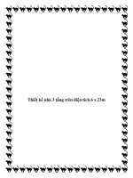
Figure 5 shows circuit breakers 1 and 2 zone-
selective interlocked.
A fault at A is seen by circuit breakers 1 and 2.
Circuit breaker 2 trips instantaneously and also
informs circuit breaker 1 to obey set delay
times. Thus, circuit breaker 2 trips and clears
the fault. Circuit breaker 1 does not trip.
A fault at B is seen by circuit breaker 1. Circuit
breaker 1 trips instantaneously since it did not
receive a signal from the downstream circuit
breaker 2. Circuit breaker 1 trips and clears the
fault. Circuit breaker 2 does not trip.
NOTE: Setting short-time delay (tsd) or ground-
fault delay (tg) to the 0 setting will eliminate
selectivity for that circuit breaker.
TRIP UNIT SWITCHES
Long-time Protection
Long-time protection protects equipment against
overloads.
Long-time protection is standard on all trip
units.
The long-time pickup (Ir) (A) sets maximum
current level (based on sensor plug rating In)
which circuit breaker will carry continuously. If
current exceeds this value, circuit breaker will
trip after the preset time delay. The long-time
pickup (Ir) is adjustable from 0.4–1.0 times the
sensor plug rating (In).
The long-time delay (tr) (B) sets the length of
time that the circuit breaker will carry an
overcurrent below the short-time or
instantaneous pickup current level before
tripping. See Table 1 for long-time delay
settings.
Both long-time pickup and long-time delay are
on the field-replaceable adjustable rating plug.
To change settings to more precisely match the
application, various rating plugs are available.
For instructions on replacing the rating plug,
see Section 4—Adjustable Rating Plug
Replacement.
For MASTERPACT
®
NT and NW circuit
breakers, the In value can be changed by
replacing the sensor plug below the trip unit.
For further information, see the instructions
packed with the sensor plug replacement kit.
The overload indicator light (C) indicates that
the Ir long-time pickup threshold has been
exceeded.
Long-time protection uses true RMS
measurement.
Thermal imaging provides continuous
temperature rise status of the wiring, both before
Figure 5: Zone-selective Interlocking
Figure 6: Long-time Protection Switches
Table 1: MICROLOGIC Trip Unit Long-time Delay Values
Setting Long-time Delay in Seconds
tr at 1.5 x Ir
12.5 25 50 100 200 300 400 500 600
tr at 6 xIr 0.5124812162024
tr at 7.2 xIr 0.34 0.69 1.38 2.7 5.5 8.3 11 13.8 16.6
In = sensor rating.
Ir = In x long-time pickup.
Trip threshold between 1.05 and 1.20 Ir.
Time-delay accuracy +0/-20%.
06133376
1
B
2
A
.4
.5
.6
.7
.8
.9
.95
.98
1
delay
short time
I itsd
(s)
on I
2
t
.2
.3
.4
.4
.1
.2
.3
.1
0
off
instantaneous
long time
alarm
Ir
x In
.5
1
2
4
8
12
16
20
tr
(s)
@ 6 Ir
24
setting
x Ir
2
2.5
3
4
5
6
8
10
Isd
1.5
x In
3
4
6
8
10
12
15
off
2
x In
2
3
4
5
6
8
10
12
1.5
setting
Ii
instantaneous
long time
alarm
tr
(s)
.4
.5
.6
.7
.8
.9
.95
.98
1
Ir
x In
.5
1
2
4
8
12
16
20
@ 6 Ir
24
.4
.5
.6
.7
.8
.9
.95
.98
1
delay
short time
I itsd
(s)
on
I
2
t
.
2
.
3
.
4
.
4
.
1
.
2
.
3
.
1
0
off
instantaneous
long time
alarm
Ir
x In
ground fault
B
C
D
E
F
G
H
J
Ig
tg
(s)
on
I
2
t
.
2
.
3
.
4
.
4
.
1
.
2
.
3
.
1
0
off
A
.5
1
2
4
8
12
16
20
tr
(s)
@ 6 Ir
24
setting
x Ir
2
2.5
3
4
5
6
8
10
Isd
1.5
x In
3
4
6
8
10
12
15
off
2
test
06133203
06133204
MICROLOGIC 3.0A Trip Unit MICROLOGIC 5.0A Trip Unit MICROLOGIC 6.0A Trip Unit
06133351
C
A
B
C
A
B
C
A B
11
© 1999–2001 Schneider Electric All Rights Reserved
Bulletin No. 48049-136-02 MICROLOGIC
®
3.0A, 5.0A and 6.0A Electronic Trip Units
4/01 Section 1—General Information
English
and after the device trips. This allows the circuit
breaker to respond to a series of overload
conditions which could cause conductor
overheating, but would go undetected if the long-
time circuit was cleared every time the load
dropped below the pickup setting or after every
tripping event.
NOTE: If checking trip times, wait a minimum of
15 minutes after circuit breaker trips before
resetting to allow the thermal imaging to reset
completely to zero or use a test kit to defeat the
thermal imaging.
Short-time Protection
Short-time protection protects equipment against
short circuits.
Short-time protection is standard on 5.0A and
6.0A trip units. It is not available on 3.0A trip
units.
The short-time pickup (Isd) (A) sets current level
(below instantaneous trip level) at which circuit
breaker will trip after the preset time delay.
The short-time delay (tsd) (B) sets the length of
time that the circuit breaker will carry an
overcurrent above the short-time pickup current
level before tripping.
The I
2
t on/I
2
t off option provides improved
selectivity with downstream protective devices:
– With I
2
t off selected, fixed time delay is
provided.
– With I
2
t on selected, inverse time I
2
t
protection is provided up to 10 x Ir. Above 10
x Ir, fixed time delay is provided.
Intermittent currents in the short-time tripping
range which do not last sufficiently long to
trigger a trip are accumulated and shorten the
trip delay appropriately.
Short-time protection can be zone-selective
interlocked (ZSI) with upstream or downstream
circuit breakers.
Setting tsd to the 0 setting turns off zone-
selective interlocking.
Short-time protection uses true RMS
measurement.
Short-time pickup and delay can be adjusted to
provide selectivity with upstream or
downstream circuit breakers.
NOTE: Using the I
2
t on functionality in a zone
selective interlocking (ZSI) scheme is not
recommended. It is possible, due to the delay in
the upstream device receiving a restraint signal,
that the trip unit could trip in a time shorter than
the published trip curve. The I
2
t off functionality
will coordinate properly in a ZSI system.
Figure 7: Short-time Protection Switches
Table 2: MICROLOGIC Trip Unit Short-time Delay Values
Setting Short-time Delay
I
2
t off (ms at 10 Ir) (seconds) 0 0.1 0.2 0.3 0.4
I
2
t on (ms at 10 Ir) (seconds) 0.1 0.2 0.3 0.4
tsd (min. trip) (milliseconds) 20 80 140 230 350
tsd (max. trip) (milliseconds) 80 140 200 320 500
.4
.5
.6
.7
.8
.9
.95
.98
1
delay
short time
I itsd
(s)
on I
2
t
.2
.3
.4
.4
.1
.2
.3
.1
0
off
instantaneous
long time
alarm
Ir
x In
.5
1
2
4
8
12
16
20
tr
(s)
@ 6 Ir
24
setting
x Ir
2
2.5
3
4
5
6
8
10
Isd
1.5
x In
3
4
6
8
10
12
15
off
2
.4
.5
.6
.7
.8
.9
.95
.98
1
delay
short time
I itsd
(s)
on
I
2
t
.2
.3
.4
.4
.1
.2
.3
.1
0
off
instantaneous
long time
alarm
Ir
x In
ground fault
B
C
D
E
F
G
H
J
Ig
tg
(s)
on
I
2
t
.2
.3
.4
.4
.1
.2
.3
.1
0
off
A
.5
1
2
4
8
12
16
20
tr
(s)
@ 6 Ir
24
setting
x Ir
2
2.5
3
4
5
6
8
10
Isd
1.5
x In
3
4
6
8
10
12
15
off
2
test
06133204
A
B
MICROLOGIC 5.0A MICROLOGIC 6.0A
06133351
A
B
Trip Unit
Trip Unit
© 1999–2001 Schneider Electric All Rights Reserved
12
MICROLOGIC
®
3.0A, 5.0A and 6.0A Electronic Trip Unit Bulletin No. 48049-136-02
Section 1—General Information 4/01
English
Instantaneous Protection
Instantaneous protection protects equipment
against short circuits with no intentional time
delay.
Instantaneous protection (Ii) (A) is standard on
all trip units.
Instantaneous protection is based on the circuit
breaker sensor rating (In).
Circuit breaker open command is issued as
soon as threshold current is exceeded.
Instantaneous protection uses peak current
measurement.
When instantaneous protection switch is set to
off, the instantaneous protection is disabled.
Ground-fault Protection for Equipment
Equipment ground-fault protection protects
conductors against overheating and faults from
ground-fault currents (≤ 1200 A).
Equipment ground-fault protection is standard
on 6.0A trip units.
Ground-fault pickup (Ig) (A) sets ground current
level where circuit breaker will trip after the
preset time delay.
Ground-fault delay (tg) (B) sets the length of
time that the circuit breaker will carry a ground-
fault current above the ground-fault pickup
current level before tripping.
Equipment ground-fault protection can be zone-
selective interlocked (ZSI) with upstream or
downstream circuit breakers.
Setting the ground-fault delay (tg) to the 0
setting turns off zone-selective interlocking.
Neutral protection and equipment ground-fault
protection are independent and can operate
concurrently.
NOTE: Using the I
2
t on functionality in a zone
selective interlocking (ZSI) scheme is not
recommended. It is possible, due to the delay in
the upstream device receiving a restraint signal,
that the trip unit could trip in a time shorter than
the published trip curve. The I
2
t off functionality
will coordinate properly in a ZSI system.
Figure 8: Instantaneous Protection Switches
Table 3: MICROLOGIC Trip Unit Instantaneous Values
Setting Trip Unit Type Interruption Current
Ii (= In x ) 3.0A
1.52345681012
Ii (= In x ) 5.0A and 6.0A 23468101215OFF
Ii = instantaneous pickup.
In = sensor rating.
Ir = long-time delay pickup.
Figure 9: Ground-fault Protection Switches
Table 4: MICROLOGIC Trip Unit Ground-fault Pickup Values
Ig (= In x ) A B C D E F G H J
In
≤ 400 A 0.3 0.3 0.4 0.5 0.6 0.7 0.8 0.9 1
400 A < In ≤ 1200 A 0.2 0.3 0.4 0.5 0.6 0.7 0.8 0.9 1
In > 1200 A 500 A 640 A 720 A 800 A 880 A 960 A 1040 A 1120 A 1200 A
In = sensor rating.
Ig = ground-fault pickup.
Table 5: MICROLOGIC Trip Unit Ground-fault Delay Values
Setting Ground-fault Delay
I
2
t off time delay at 10 Ir (seconds) 0 0.1 0.2 0.3 0.4
I
2
t on time delay at 10 Ir (seconds) 0.1 0.2 0.3 0.4
tg (min. trip) (milliseconds) 20 80 140 230 350
tg (max. trip) (milliseconds) 80 140 200 320 500
.4
.5
.6
.7
.8
.9
.95
.98
1
delay
short time
I itsd
(s)
on I
2
t
.2
.3
.4
.4
.1
.2
.3
.1
0
off
instantaneous
long time
alarm
Ir
x In
.5
1
2
4
8
12
16
20
tr
(s)
@ 6 Ir
24
setting
x Ir
2
2.5
3
4
5
6
8
10
Isd
1.5
x In
3
4
6
8
10
12
15
off
2
x In
2
3
4
5
6
8
10
12
1.5
setting
Ii
instantaneous
long time
alarm
tr
(s)
.4
.5
.6
.7
.8
.9
.95
.98
1
Ir
x In
.5
1
2
4
8
12
16
20
@ 6 Ir
24
.4
.5
.6
.7
.8
.9
.95
.98
1
delay
short time
I itsd
(s)
on
I
2
t
.2
.3
.4
.4
.1
.2
.3
.1
0
off
instantaneous
long time
alarm
Ir
x In
ground fault
B
C
D
E
F
G
H
J
Ig
tg
(s)
on
I
2
t
.2
.3
.4
.4
.1
.2
.3
.1
0
off
A
.5
1
2
4
8
12
16
20
tr
(s)
@ 6 Ir
24
setting
x Ir
2
2.5
3
4
5
6
8
10
Isd
1.5
x In
3
4
6
8
10
12
15
off
2
test
06133203
06133204
A A
MICROLOGIC 3.0A
MICROLOGIC 5.0A MICROLOGIC 6.0A
06133351
A
Trip Unit Trip Unit
Trip Unit
.4
.5
.6
.7
.8
.9
.95
.98
1
delay
short time
I itsd
(s)
on
I
2
t
.
2
.
3
.
4
.
4
.
1
.
2
.
3
.
1
0
off
instantaneous
long time
alarm
Ir
x In
ground fault
B
C
D
E
F
G
H
J
Ig
tg
(s)
on
I
2
t
.
2
.
3
.
4
.
4
.
1
.
2
.
3
.
1
0
off
A
.5
1
2
4
8
12
16
20
tr
(s)
@ 6 Ir
24
setting
x Ir
2
2.5
3
4
5
6
8
10
Isd
1.5
x In
3
4
6
8
10
12
15
off
2
test
MICROLOGIC 6.0A Trip Unit
06133351
A
B
13
© 1999–2001 Schneider Electric All Rights Reserved
Bulletin No. 48049-136-02 MICROLOGIC
®
3.0A, 5.0A and 6.0A Electronic Trip Units
4/01 Section 1—General Information
English
INDICATOR LIGHTS
Overload Indicator Light
The overload indicator light (A) lights when the Ir
long-time pickup level has been exceeded.
Trip Indicator Lights
The Ir trip indicator light (A) lights when a trip
occurs because the Ir long-time pickup level was
exceeded.
The Isd/Ii trip indicator light (B) lights when a trip
occurs because the Isd short-time pickup or the Ii
instantaneous pickup was exceeded.
The Ig trip indicator light (C) lights when a trip
occurs because the Ig ground fault pickup was
exceeded.
Self-protection Indicator Light
The Ap self-protection indicator light (A) lights
when the trip unit overheats, the ultimate
instantaneous (DIN) is exceeded, or a trip unit
power supply failure occurs.
AMMETER
The ammeter monitors and displays the circuit
breaker currents. An alphanumeric screen (A)
continuously displays the phase at the highest
load. Navigation buttons (B) can be pressed to
display the various monitored currents.
The process of checking the ammeter values can
be stopped at any time. After several seconds,
MICROLOGIC trip units automatically return to
displaying the phase at the highest load.
See the following section for addition information
concerning the ammeter.
Figure 10: Overload Indictor Light
Figure 11: Trip Indicator Lights
Figure 12: Self-protection Indicator Light
Figure 13: Ammeter
.4
.5
.6
.7
.8
.9
.95
.98
1
delay
short time
I itsd
(s)
on I
2
t
.2
.3
.4
.4
.1
.2
.3
.1
0
off
instantaneous
long time
alarm
Ir
x In
ground fault
B
C
D
E
F
G
H
J
Ig
tg
(s)
on I
2
t
.2
.3
.4
.4
.1
.2
.3
.1
0
off
A
.5
1
2
4
8
12
16
20
tr
(s)
@ 6 Ir
24
setting
x Ir
2
2.5
3
4
5
6
8
10
Isd
1.5
x In
3
4
6
8
10
12
15
off
2
test
40
%
%
100
06133351
A
06133204
Micrologic 6.0 A
CBA
06133246
Micrologic 6.0 A
A
06133246
40
100
%
%
menu
long time
06133246
A
B
© 1999–2001 Schneider Electric All Rights Reserved
14
MICROLOGIC
®
3.0A, 5.0A and 6.0A Electronic Trip Unit Bulletin No. 48049-136-02
Section 1—General Information 4/01
English
TRIP UNIT TESTING
Trip unit functions can be tested using primary
injection testing or secondary injection testing.
EXTERNAL POWER SUPPLY
To provide power to the ammeter when the circuit
breaker is not carrying load current, a 24 Vdc
external power supply can be used.
Connections UC3
F1 (-)
F2 (+)
24 Vdc
HAZARD OF SHOCK, BURN OR EQUIPMENT DAMAGE
Trip unit and communication module must use separate power supplies.
Failure to observe this instruction can result in personal injury or
equipment damage.
CAUTION
!
15
© 1999–2001 Schneider Electric All Rights Reserved
Bulletin No. 48049-136-02 MICROLOGIC
®
3.0A, 5.0A and 6.0A Electronic Trip Units
4/01 Section 2—Ammeter
English
Figure 14: Ammeter
Figure 15: Menus
Figure 16: Navigation Buttons
menu
06133246
B
C
A
D
40
100
%
%
A
Ir=
40
100
%
%
A
Max
40
100
%
%
A
06133354
1.125 x Ir
1 x Ir
0.8 x Ir
0.6 x Ir
0.4 x Ir
06133355
A—Currents
B—Peak Currents
C—Switch Settings
06133353
menu
BA
06133356
Section 2—Ammeter
DISPLAY
NOTE: The ammeter display will function only if
the trip unit is powered. The trip unit is powered by
the circuit breaker carrying more than 0.20 x In of
load current or by being connected to a 24 Vdc
external power supply.
A—Alphanumeric screen: Displays ammeter
information
B—Bar graph: Displays currents using an LED
bar graph
C—Menu button: Used to navigate between the
various menus
D—Scroll button: Used to scroll to the next screen
in the menus
The default display is the current value of the
phase at the highest load.
If no information is displayed, contact the local
field office.
ACCESS INFORMATION
Three different menus can be accessed:
A—Current measurements
B—Stored peak current measurements
C—Switch settings
In addition, the ammeter can be used to address
the breaker communication module (BCM) in
circuit breakers which have the optional breaker
communication module installed.
To access the next menu, press the “menu”
button (A). To access the next screen in a menu,
press the scroll button (B).
© 1999–2001 Schneider Electric All Rights Reserved
16
MICROLOGIC
®
3.0A, 5.0A and 6.0A Electronic Trip Units Bulletin No. 48049-136-02
Section 2—Ammeter 4/01
English
Current Menu
The current (default) menu displays:
A—Phase current (IA) in A phase
B—Phase current (IB) in B phase
C—Phase current (IC) in C phase
D—Ground-fault current (Ig) (MICROLOGIC 6.0A
trip units only)
E—Neutral current (In)
To display next current, press scroll button.
NOTE: Neutral current is only monitored on a
four-pole circuit breaker with neutral protection
set to 1/N or 1xN.
Figure 17: Current Measurements
40
100
%
%
A
menu
40
100
%
%
A
menu
40
100
%
%
A
menu
40
100
%
%
A
menu
40
100
%
%
A
menu
40
100
%
%
A
06133354
06133356
06133343
06133356
06133345
A—A Phase Current (IA)
E—Neutral Current (In)
B—B Phase Current (IB)
C—C Phase Current (IC) D—Ground-fault Current (Ig)
0613334206133344
Return to A-phase Current
0613335506133354
17
© 1999–2001 Schneider Electric All Rights Reserved
Bulletin No. 48049-136-02 MICROLOGIC
®
3.0A, 5.0A and 6.0A Electronic Trip Units
4/01 Section 2—Ammeter
English
Peak Menu
To access the peak menu:
1. Current menu (A) is displayed.
2. Press “menu” button (B).
3. Peak menu (C) appears.
4. To access menu screens, press scroll button
(D).
The peak menu displays:
A—Peak current (IpA) in A phase
B—Peak current (IpB) in B phase
C—Peak current (IpC) in C phase
D—Peak ground-fault current (Ipg)
(MICROLOGIC 6.0A trip unit only)
E—Peak neutral current (Ipn)
To display next peak current, press scroll button.
To reset max values, scroll to the max value
screen and hold the menu button for three
seconds.
Figure 18: Access the Peak Menu
Figure 19: Peak Currents
menu
menu
40
100
%
%
A
Max
40
100
%
%
A
061333550613335606133354
C
B
A
D
menu
40
100
%
%
A
Max
menu
40
100
%
%
A
Max
menu
40
100
%
%
A
Max
menu
40
100
%
%
A
Max
40
100
%
%
A
Max
menu
40
100
%
%
A
Max
06133355
06133355
06133347
06133356
06133349
A—Peak A-phase Current (IpA)
E—Peak Neutral Current (Ipn)
B—Peak B-phase Current (IpB)
C—Peak C-phase Current (IpC)
D—Peak Ground-fault Current (Ipg)
06133346
06133348
Return to Peak A-phase Current
06133356
06133355
© 1999–2001 Schneider Electric All Rights Reserved
18
MICROLOGIC
®
3.0A, 5.0A and 6.0A Electronic Trip Units Bulletin No. 48049-136-02
Section 2—Ammeter 4/01
English
Switch Settings Menu
The switch settings menu displays the values at
which the switches are set.
To access the switch settings menu:
1. Peak menu (A) is displayed.
2. Press “menu” button (B).
3. Switch settings menu (C) will appear.
4. To access menu screens, press scroll button
(D).
The switch settings menu displays:
A—Long-time pickup (Ir) setting
B—Long-time delay (tr) setting
C—Short-time pickup (Isd) setting
D—Short-time delay (tsd) setting
E—Instantaneous delay (Ii) setting
F—Ground-fault pickup (Ig) setting (6.0A trip
units)
G—Ground-fault delay (tg) setting (6.0A trip units)
To display next switch setting, press scroll button.
To return to the current menu:
1. Switch settings menu (A) is displayed.
2. Press “menu” button (B).
3. Current menu (C) will appear.
Or wait several seconds and ammeter will
automatically return to the current (i.e., default)
menu.
Figure 20: Access the Switch Settings Menu
Figure 21: Trip Unit Settings
Figure 22: Return to the Current Menu
menu
menu
40
100
%
%
A
Ir=
40
100
%
%
A
Max
0613335306133355
A
06133356
C
B
D
menu
A
Ir=
menu
s
tg=
menu
A
Ig=
menu
A
Ii=
menu
tsd=
s
menu
A
Isd=
menu
s
tr=
menu
A
Ir=
06133382
06133356
A—Ir Setting
B—tr Setting
0613338306133384
C—Isd Setting
D—tsd Setting
06133385
06133387
G—Ig Setting
Return to Ir Switch Setting
06133388
0613338906133382
F—Ii Setting
H—tg Setting
menu
40
100
%
%
A
40
100
%
%
A
Ir=
06133353061333545
06133355
C
B
A
19
© 1999–2001 Schneider Electric All Rights Reserved
Bulletin No. 48049-136-02 MICROLOGIC
®
3.0A, 5.0A and 6.0A Electronic Trip Units
4/01 Section 2—Ammeter
English
COMMUNICATION MODULE SCREENS
The circuit breaker communication module
addressing menu is used to set the circuit breaker
communication module addresses. This section
applies only to those units which have the optional
communication module installed.
NOTE: Communications module addressing is
done only when setting up the system. Altering
settings on an operating system can cause
communications failure.
To access the communciation module menu:
1. Current menu is displayed.
2. Simultaneously press both “menu” button and
scroll button for three seconds.
3. Communication module addressing menu will
appear.
The communication module menu displays:
A—Communication module address
B—Baud rate
C—Parity screen
D—Language screen
To enter screen value into memory, press scroll
button and hold until display stops flashing.
Ammeter display will return to the default screen.
Figure 23: Communication Module Addressing
Figure 24: Communication Module Addressing Screens
menu
40
100
%
%
40
100
%
%
A
menu
0613335406133703
Current Menu
Communications Address
06133356
40
100
%
%
40
100
%
%
40
100
%
%
40
100
%
%
40
100
%
%
40
100
%
%
06133703
06134889
A—Communication Module Address
B—Baud Rate
06133704
C—Parity
06133356
06133705
06134888
D—Language
06134889
© 1999–2001 Schneider Electric All Rights Reserved
20
MICROLOGIC
®
3.0A, 5.0A and 6.0A Electronic Trip Unit Bulletin No. 48049-136-02
Section 3—Operation 4/01
English
Figure 25: Adjust Switch Settings
Figure 26: Circuit Breaker Rating
Figure 27: Set Pickup Levels
Micrologic 2.0
M
i
c
r
o
l
o
g
i
c
2
.
0
M
i
c
r
o
l
o
g
i
c
2
.
0
061332050613320606133207
A
B
C
I
n
=
2
0
0
0
A
In = 2000 A
M
ic
ro
lo
g
ic
2
.0
06133206
In = 2000 A
Ir = 0.7 x In = 1400 A
Ii = 3 x In = 6000 A
alarm
x In
2
3
4
5
6
8
10
12
1.5
setting
Ii
instantaneous
.4
.5
.6
.7
.8
.9
.95
.98
1
long time
Ir
x In
0 I
t
Ir
Ii
1400 A
6000 A
0613321006133209
Section 3—Operation
ADJUST SWITCH SETTINGS
1. Open switch cover (A).
2. Adjust the appropriate switches (B) to desired
values.
3. Replace switch cover. Use a lead seal (C), if
necessary, to provide tamper evidence.
EXAMPLES
Circuit breaker is rated 2000 A.
MICROLOGIC 3.0A Trip Unit
1. Set pickup levels.
21
© 1999–2001 Schneider Electric All Rights Reserved
Bulletin No. 48049-136-02 MICROLOGIC
®
3.0A, 5.0A and 6.0A Electronic Trip Units
4/01 Section 3—Operation
English
2. Set time delay.
MICROLOGIC 5.0A Trip Unit
1. Set pickup levels.
2. Set time delays.
Figure 28: Set Time Delay
Figure 29: Set Pickup Levels
Figure 30: Set Time Delays
long time
alarm
.5
1
2
4
8
12
16
20
tr
(s)
@ 6 Ir
24
tr = 1 s (at 6 x Ir)
0613321106133212
0 I
t
tr
6 x Ir
1 s
In = 2000 A
Ir = 0.7 x In = 1400 A
Ii = 3 x In = 6000 A
Isd = 2 x Ir = 2800 A
.4
.5
.6
.7
.8
.9
.95
.98
1
setting
short time
I i
x Ir
2
2.5
3
4
5
6
8
10
Isd
1.5
off
instantaneous
long time
alarm
Ir
x In
x In
3
4
6
8
10
12
15
off
2
0613321306133214
Ir
Isd
Ii
0
I
t
1400 A
2800 A
6000 A
tr = 1 s (at 6 x Ir)
tsd = 0.2 s I
2
t on
short time
long time
alarm
.5
1
2
4
8
12
16
20
tr
(s)
@ 6 Ir
24
delay
tsd
on
I
2
t
.2
.3
.4
.4
.1
.2
.3
.1
0
I
2
t on
I
2
t off
off
tr
tsd
0
I
t
6 x Ir
10 x Ir
1 sec
0.2 sec
06133215
06133217
© 1999–2001 Schneider Electric All Rights Reserved
22
MICROLOGIC
®
3.0A, 5.0A and 6.0A Electronic Trip Unit Bulletin No. 48049-136-02
Section 3—Operation 4/01
English
MICROLOGIC 6.0A Trip Unit
1. Set pickup levels.
2. Set time delays.
Figure 31: Set Pickup Levels
Figure 32: Set Time Delays
short time
instantaneous
long time
alarm
ground fault
setting
.
.5
.6
.7
.8
.9
.95
.98
1
Ir
x In
x Ir
2
2.5
3
4
5
6
8
10
Isd
1.5
B
C
D
E
F
G
H
J
Ig
A
Ii
x In
3
4
6
8
10
12
15
off
2
In = 2000 A
Ir = 0.7 x In = 1400 A
Ii = 3 x In = 6000 A
Isd = 2 x Ir = 2800 A
B Ig = 640 A
Ir
Isd
Ii
0
I
t
1400 A
2800 A
6000 A
06133214
06133357
06133360
0 I
t
Ig
640 A
short time
instantaneous
long time
alarm
ground fault
.5
1
2
4
8
12
16
20
tr
(s)
@ 6 Ir
24
delay
tsd
(s)
on I
2
t
.2
.3
.4
.4
.1
.2
.3
.1
0
off
tg
(s)
on I
2
t
.2
.3
.4
.4
.1
.2
.3
.1
0
off
tr = 1 s (at 6 x Ir)
tsd = 0.2 s I
2
t on
tg = 0.2 s I
2
t on
I
2
t on I
2
t off
tr
tsd
0
I
t
6 x Ir
10 x Ir
1 sec
0.2 sec
0 I
t
tg
0.2 sec
06133358
06133217
06133362
23
© 1999–2001 Schneider Electric All Rights Reserved
Bulletin No. 48049-136-02 MICROLOGIC
®
3.0A, 5.0A and 6.0A Electronic Trip Units
4/01 Section 3—Operation
English
ZONE-SELECTIVE INTERLOCKING (ZSI)
The number of devices which can be interlocked
are shown in Table 6.
1. Circuit breaker terminals are shipped with
terminals Z3, Z4 and Z5 jumpered to self-
restrain the short-time and ground-fault
functions. Remove the jumpers when
activating zone-selective interlocking.
Table 6: ZSI Combinations
MICROLOGIC #.0x Trip Units
Square D MICROLOGIC Series B Trip Units
Square D GC-100 Ground-fault Relay
for Equipment Protection
Square D GC-200 Ground-fault Relay for
Equipment Protection
Merlin Gerin STR58 Trip Units
Federal Pioneer USRC and USRCM Trip Units
MICROLOGIC #.0x Trip Units 15 R R 15 15 R
Square D MICROLOGIC Series B Trip
Units
R26RRR15
Square D GC-100 Ground-fault Relay for
Equipment Protection
RR7 R RR
Square D GC-200 Ground-fault Relay for
Equipment Protection
15 R R 15 15 R
Merlin Gerin STR58 Trip Units 15 R R 15 15 R
Merlin Gerin STR53 Trip Units 15 R R 15 15 R
Federal Pioneer USRC and USRCM Trip
Units
R15RRR15
Square D Add-on Ground Fault Module
for Equipment Protection
R5RRRR
R—RIM module is required to restrain any devices.
Figure 33: Jumpered Terminals
Upstream Device
Downstream Device
(sends output to RIM)
(receives input from RIM)
Auxiliary Connections
Z5
M1
Z3
Z4
Z1 Z2
UC1
© 1999–2001 Schneider Electric All Rights Reserved
24
MICROLOGIC
®
3.0A, 5.0A and 6.0A Electronic Trip Unit Bulletin No. 48049-136-02
Section 3—Operation 4/01
English
2. Wire circuit breakers for zone-selective
interlocking.
SET COMMUNICATION MODULE
VALUES
If the optional circuit breaker communication
module (BCM) is installed, use the ammeter to set
communication module values.
To access the communciation module menu:
1. Current menu (A) is displayed.
2. Simultaneously press both “menu” button (B)
and scroll button (C) down for three seconds.
3. Communication module addressing menu (D)
will appear.
Figure 34: ZSI Wiring Example
Figure 35: Access Communication Module Menu
Auxiliary
Z5
M1
Z3
Z4
Z1
Z2
UC1
Z5
M1
Z3
Z4
Z1 Z2
UC1
Z5
M1
Z3
Z4
Z1 Z2
UC1
Auxiliary
Secondary
Connector
Position
Description
Z1
Z2
Z4
Z5
ZSI out signal
ZSI in short time
ZSI out
ZSI in ground fault
Z3
ZSI in signal
Connections 1
Auxiliary
Connections 2
Connections 3
40
100
%
%
40
100
%
%
40
100
%
%
A
menu
0613335406133703
Current Menu
Communications Address
06133356
B
C
A
E
D
25
© 1999–2001 Schneider Electric All Rights Reserved
Bulletin No. 48049-136-02 MICROLOGIC
®
3.0A, 5.0A and 6.0A Electronic Trip Units
4/01 Section 3—Operation
English
Set communication module values:
1. Press and release scroll button (A) to
sequence addresses (1 through 47). When
the correct address number is reached, enter
the value by pressing and holding scroll button
(B) until the display stops flashing.
Baud rate screen (C) will appear after address
has been entered.
2. Press and release scroll button (D) to
sequence baud rates (4.8k, 9.6k or 19.2k).
When the desired baud rate appears, enter
the value by pressing and holding scroll button
(E) until the display stops flashing.
Parity screen (F) will appear after baud rate
has been entered.
3. Press and release scroll button (G) to
sequence parities (E [even] or n [none]).
When the desired parity appears, enter the
value by pressing and holding scroll button (H)
until the display stops flashing.
Languages screen (I) will appear after parity
has been entered.
4. Press and release scroll button (J) to scroll
through languages (French [Fr], US English
[En US], UK English [En], German [d],
Spanish [SP] or Italian [It]). When the desired
language appears, enter the value by pressing
and holding scroll button (J) until the display
stops flashing.
Ammeter display will return to the default
screen after language is entered.
After the communication module values have
been set, ammeter will automatically return to the
current (i.e., default) menu.
After setting communication module values,
drawout circuit breakers must have the cradle
communication module, if available, activated. For
drawout circuit breakers, refer to the cradle
communication module instructions to complete
setup.
Figure 36: Setting Communication Module Addresses
40
100
%
%
40
100
%
%
40
100
%
%
40
100
%
%
40
100
%
%
40
100
%
%
40
100
%
%
40
100
%
%
40
100
%
%
06133703
06134489
06133704
Communciations Address
Baud Rate
06133704
Parity
0613335606133705
Baud Rate
Parity
0613335406133705
06134488
C
B
E
F
D
H
A
Language
I
G
0613335406133705
06134488
K
40
100
%
%
Language
J
© 1999–2001 Schneider Electric All Rights Reserved
26
MICROLOGIC
®
3.0A, 5.0A and 6.0A Electronic Trip Unit Bulletin No. 48049-136-02
Section 3—Operation 4/01
English
CHECK TRIP UNIT SETTINGS
Use the ammeter switch setting menu to check
the trip unit settings.
1. Press “menu” button twice.
2. Switch settings menu will appear.
3. Press scroll button to advance to next screen.
4. After checking trip unit settings, press “menu”
button once to return to main menu.
VERIFY TRIP UNIT OPERATION
Use a test kit connected to the trip unit test plug
(A) to verify trip unit is functioning as desired. See
instructions shipped with test kit to perform
verification tests.
Table 7: Trip Unit Settings
Setting Window 3.0A 5.0A 6.0A
Ir Long-time pickup X X X
tr Long-time delay X X X
Isd Short-time pickup X X
tsd Short-time delay X X
Ii Instantaneous pickup X X X
Ig Ground-fault pickup X
tg Ground-fault delay X
Figure 37: Verify Trip Unit Operation
A
Ir=
s
tr=
A
Isd=
tsd=
s
A
Ii=
A
Ig=
s
tg=
M
i
c
r
o
l
o
g
i
c
2
.
0
06133218
06133205
M
i
c
r
o
l
o
g
i
c
2
.
0
A
27
© 1999–2001 Schneider Electric All Rights Reserved
Bulletin No. 48049-136-02 MICROLOGIC
®
3.0A, 5.0A and 6.0A Electronic Trip Units
4/01 Section 3—Operation
English
TEST EQUIPMENT GROUND-FAULT TRIP
FUNCTIONS
With the circuit breaker closed, test the ground-
fault (MICROLOGIC 6.0A trip unit) trip functions.
For instructions on how to close circuit breaker,
refer to the circuit breaker installation instructions
shipped with the circuit breaker.
1. Open the switch cover (A).
2. Press the ground-fault test button (B). Circuit
breaker should trip.
3. Close the switch cover.
If circuit breaker does not trip, contact the local
field office.
RESET TRIP UNIT AFTER TRIP
When the circuit breaker trips, the fault indicator
will remain lit until the trip unit is reset.
Press and hold the reset/test button (A) for three
seconds to reset the trip unit after trip.
Do not return circuit breaker to service until cause
of trip is determined. For more information, refer to
the circuit breaker installation instructions shipped
with the circuit breaker.
CHECK TRIP UNIT STATUS
NOTE: Trip unit must be powered to test battery.
The trip unit is powered if the circuit breaker is
carrying more than 0.20 x In of load current or if
the 24 Vdc external power supply is connected.
To check trip unit battery and trip indicators, press
the test/reset button (A).
All trip indicators (B) will light up
Battery status will be displayed
If no battery status is displayed, there is no battery
installed.
For instructions on replacing battery, see Section
6—Battery Replacement.
Figure 38: Test Equipment Ground-fault Trip Function
Figure 39: Reset Trip Unit After Trip
Figure 40: Check Trip Unit Status
M
i
c
r
o
l
o
g
i
c
2
.
0
06133218
06133205
M
i
c
r
o
l
o
g
i
c
7
.
0
A
4
0
1
0
0
%
%
m
e
n
u
B
A
Micrologic 6.0 A
06133378
A
Micrologic 6.0 A
06133379
A
B
06133380
Charged
Half-charged
Change battery