Tài liệu Designing with FPGAs and CPLDs- P7 docx
Bạn đang xem bản rút gọn của tài liệu. Xem và tải ngay bản đầy đủ của tài liệu tại đây (138.68 KB, 30 trang )
164 Chapter 7: Electronic Design Automation Tools
6. Static timing analysis tools
(a) Simulate a design using real timing numbers.
(b) Analyze a design for all worst-case timing and determine whether the design
meets your timing requirements.
(c) Analyze your schedule for designing a chip and determine whether it is realistic
and which tasks will take longer than expected.
(d) Determine the precise timing your design will have when it is placed and routed.
7. Place and route tools
(a) Create the bits that are used to program the device to implement your design.
(b) Place the logic for your design in the programmable device and connect that
logic together.
(c) Find you a nice home and a good way to get to work.
(d) Both a and b.
8. Select TRUE or FALSE for the following statements:
(a) TRUE or FALSE: Static timing analysis has replaced timing simulation for deter-
mining the timing numbers for FPGA designs.
(b) TRUE or FALSE: Dynamic timing analysis is a technique that will soon replace
static timing analysis.
(c) TRUE or FALSE: Scan insertion software is used to insert boundary scan chains
into an FPGA.
(d) TRUE or FALSE: Formal verification is a mathematic method of assuring that a
design meets its timing requirements.
(e) TRUE or FALSE: Floorplanning software allows you to place large chunks of
your design in specific locations on the chip.
(f) TRUE or FALSE: SRAM-based FPGAs are programmed in the system.
(g) TRUE or FALSE: Serial PROMs are often used to load a design into an
SRAM-based FPGA.
Please purchase PDF Split-Merge on www.verypdf.com to remove this watermark.
165
Chapter 8
Today and the Future
In this final chapter, I discuss some of the newer architectures and technologies
that are becoming available or are on the horizon. I give my opinions on which
ones are interesting and which aren’t, which are overhyped and which are unde-
rhyped, and which will succeed and which won’t.
Objectives
• Understand the newer devices that are becoming available or will be avail-
able in the future.
• Learn how these new technologies and design concepts relate to current
designs
8.1 Cores
By a “core” I mean the basic functionality, excluding any extraneous circuits
such as I/O buffers, that is found on a processor chip. There are two types of
cores: soft cores and hard cores. The soft core, known as an IP core, is described
by its logic function rather than by any physical implementation. Soft cores usu-
ally delivered to the customer as HDL code, which is then synthesized as part of
the customer’s design. Hard cores, on the other hand, consist of physical imple-
mentations of a function. With respect to CPLDs and FPGAs, these hard cores
In this chapter
• Cores
• Special I/O drivers
• New architectures
• ASICs with FPGA cells
Please purchase PDF Split-Merge on www.verypdf.com to remove this watermark.
166 Chapter 8: Today and the Future
are known as embedded cores because they are physically embedded onto the
die and surrounded by programmable logic.
Many of the FPGA and CPLD vendors have begun offering cores. As the den-
sity of programmable devices increases, these cores allow engineers to create
what is called a system on a programmable chip (SOPC) using a programmable
device. In other words, whereas programmable devices were initially developed
to replace glue logic, engineers can now place entire systems on a single pro-
grammable device. Systems consist of all kinds of complicated devices like pro-
cessors. In order to place these complex functions within a programmable
device, there are three options: Design the function yourself, purchase the HDL
code for the function and incorporate it into your HDL code, or get the vendor
to include the function as a cell in the programmable device. The second option
is the IP core; the third option is the embedded core.
8.1.1 IP Cores
IP cores are often sold by third-party vendors that specialize in creating these
functions. Recently, CPLD and FPGA vendors have begun offering their own
soft cores. IP cores reduce the time and manpower requirements for the FPGA
designer. IP cores have already been designed, characterized, and verified. Also,
IP cores are often modifiable, meaning that you can add or subtract functional-
ity to suit your needs.
But IP cores may also be expensive in terms of chip resources. IP cores can be
optimized to a certain degree, but the complete optimization depends on its use
in a particular device and also depends on the logic to which it is connected. IP
purchased from a third party may not be optimized for a particular CPLD or
FPGA vendor. Because of that, you may not be able to meet your speed or power
requirements, especially after you have placed and routed it.
8.1.2 Embedded Cores
The embedded core is in many ways ideal for users, which is one reason why
programmable device vendors are now offering embedded cores in their devices.
The embedded core is optimized for the vendor’s process, so that it achieves
good timing and power consumption numbers. The embedded function is
placed as a single cell on the silicon die, so its performance does not depend on
the rest of your design because it will not need to be placed and routed.
Some embedded cores are analog devices that cannot be designed into an
ordinary CPLD or FPGA. By integrating these functions into the device, you can
avoid the difficult process of designing analog devices, and save the chips and
components that would otherwise be required outside the programmable device.
Please purchase PDF Split-Merge on www.verypdf.com to remove this watermark.
Cores 167
Of course, there is a drawback to embedded cores. By using an embedded
core in your programmable device, you tie the design to a single vendor. Unless
another vendor offers the same embedded core, which is unlikely, switching to
another vendor will require a large effort and will not be pleasant.
Another reason for offering embedded cores is a business reason. There are
essentially two major players in the CPLD and FPGA markets: Xilinx and
Altera. The smaller players have tried for years to compete with the result, gen-
erally, that their market share has remained flat or shrunk. In order for the
smaller vendors to differentiate themselves from the big two, they need to find a
niche market that they can dominate. These niche markets support those designs
that need a very specific function. I should say that these niche markets may turn
out to be very big. However, it is a bet-the-house risk, especially for the smaller
companies. If a small company puts a lot of resources into developing and mar-
keting a programmable device which includes a specific processor that ends up
being designed into every personal computer, then it was a good bet. But if the
vendor bets on the wrong processor, they could lose a huge amount of R&D
money and get little revenue in return. This isn’t as big a risk for the large ven-
dors because they have more resources, more sales channels, and more cash to
quickly change directions and develop new families of devices.
8.1.3 Processor Cores
Processor cores are commonly available as IP cores or embedded cores. These
processors tend to be those that are designed for embedded systems because,
almost by definition, programmable devices are embedded systems.
If the processor core is embedded, you will be using a processor that has been
optimized and has predictable timing and power consumption numbers. For
both types of core, software development tools are readily available.
Off-the-shelf cross compilers and simulators can be used to debug code before
the design has been completed and the programmable device is available.
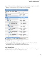
An example of an FPGA with an embedded processor, along with other
embedded cores, is shown in Figure 8.1.
8.1.4 DSP Cores
Digital signal processors (DSPs) are also commonly available as an IP core or an
embedded core. DSPs are specialized processors used for manipulating sampled
analog signals. DSPs are commonly used for audio and video filtering and com-
pression. Many engineers have argued that as general processors become faster,
DSPs will be less useful because the same functions can be accomplished on the
generic processors. However, video and audio digitization, compression, and fil-
tering requirements have increased in recent years as millions of users connect to
Please purchase PDF Split-Merge on www.verypdf.com to remove this watermark.
168 Chapter 8: Today and the Future
the Internet and regularly upload and download all kinds of information over
relatively limited bandwidth connections. So far, DSP demand for use in net-
working and graphics devices has been increasing, not decreasing.
8.1.5 Embedded PHY Cores
PHY cores are the analog circuitry that drives networks. Many companies are
now integrating this functionality onto their devices. Because these devices
include specialized analog circuitry, they are available only as embedded cores.
In the late nineties, during the heyday of the Internet, networking companies
were springing up all over. In order to save design time, these companies could
use FPGAs with PHY cores built in. Unfortunately, this boom didn’t last, and
some networking technologies did not find the mass acceptance that was pre-
dicted. For engineers designing an interface to a specific type of network, an
FPGA with the appropriate PHY core can be a very good resource. For pro-
Four 32 bit
Timers/Coutners
Two 16550
UART
36 RAM Blocks (Configurations 128x12; 256x9; 512x4; or 1024x2)
18 ECU Blocks (8x8 Multiply, 16 bit carry add)
3 APB
Slave I/F
AHB
Master/Slave
16K Bytes
SRAM
PCI-32 bit
66/33MHz
10/100
Ethernet
MAC
10/100
Ethernet
MAC
Memory
Controller
Interrupt
Controller
ECT to AHB
AHB to APB
4Kc MIPS
w/Caches
32 bit Advanced High Performance Bus
32 bit Advanced Peripheral Bus
JTAG
Configurable
Logic Analyzer
Monitor
(CLAM) - RTL Code
Via-Link Programmable Fabric
(2016 Logic Cells or
536k System Gates or
75k ASIC Gates)
Figure 8.1 FPGA with embedded processor core (courtesy of Quicklogic Corporation)
Please purchase PDF Split-Merge on www.verypdf.com to remove this watermark.
Special I/O Drivers 169
grammable device vendors, it can be something of a risk to support a particular
PHY core that may not end up being the standard that they expect or have the
mass market acceptance that they are counting on.
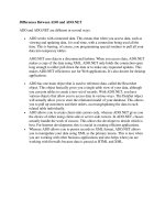
Figure 8.2 shows an example of an FPGA with an embedded PHY core that
can be programmed to interface to a variety of different networks.
8.2 Special I/O Drivers
Special I/O drivers are now being embedded into programmable devices. The
newer buses inside personal computers need special high-drive, impedance
matched drive circuits and input circuits with very specific voltage threshold val-
ues. Many vendors now offer programmable devices with I/O that meet these
special requirements. Many times, these devices are the only way to design a
programmable device that can interface with these buses.
8.3 New Architectures
Vendors are developing new architectures for CPLDs and FPGAs. Some vendors
still make occasional attempts to create a fine-grained architecture where the
logic blocks consist of small logic functions. Most of these attempts, I believe,
FPGA Logic
(up to 400K gates)
Ideal for implementing
comm. interfaces:
- XGM8
- POS-PHY4
- 153 MHz PECL
- User-Defined
Reference Clock
Transmit
PLLs
Receive
PLLs
16:64 deMUX
or
16:128 deMUX
16:64 deMUX
or
16:128 deMUX
Transmit Clock
Four 2.5Gbps Rx Clocks
64- or 128-bit
10Gb RX CLX
(161MHz-78MHz)
Receive Data:
- 16x622 or
- 16x645 or
- 16x667 Mbps
Transmit Data:
- 16x622 or
- 16x645 or
- 16x667 Mbps
10Gb Tx CLK
(161MHz-78MHz)
Figure 8.2 FPGA with embedded
PHY core (copyright 2002
by Lattice Semiconductor
Corporation)
Please purchase PDF Split-Merge on www.verypdf.com to remove this watermark.
170 Chapter 8: Today and the Future
are doomed to failure because routing is still the main constraint in any FPGA.
Fine-grained architectures require more routing than large-grained architectures.
One type of architecture being developed has a logic block based on a DSP, as
seen in Figure 8.3. This type of FPGA will be better for use in chips that need a
significant amount of signal processing. I have certain doubts about this future
path, though. First, the majority of programmable devices do not perform any
DSP, so this architecture targets a relatively small market. Second, special tools
will be needed to convert digital signaling algorithms for use in such a special-
ized FPGA. These tools will need to optimize the algorithm very well so that the
FPGA realization can actually perform better than a standard DSP, or a generic
processor, running code that has been optimized using tools and compilers that
have been available for years.
8.4 ASICs with Embedded FPGA Cells
A relatively new concept is to embed FPGAs into ASICs. Vendors are approach-
ing this embedded logic two different ways. One way is to create small pro-
grammable cells of logic that can be used in an ASIC. These cells are similar to
the configurable logic blocks of an FPGA, and vendors could place them, along
with hard logic cells, anywhere on an ASIC. The other way is to embed an
FPGA core into an ASIC and allow logic to be placed around this core.
The technology of providing FPGA cells for ASIC designs is an interesting
one. I don’t have a good feel for the size of this market, though I feel that a mar-
ket definitely exists. I see potential in several specific areas:
• Cost reduction. For engineers who are already designing systems that include
both ASICs and FPGAs, putting FPGA cells inside the ASIC combines multi-
ple chips into one hybrid chip. This will result in a significant cost savings by
Optional Output
Registers
Optional Pipeline
Registers
Optional Input
Registers
Multiplier
Adder/
Subtractor/
Accumulator
Summation
Unit
Memory & DSP Blocks Placed
for Optimum Data Transfer
M4K
RAM Blocks
M512
RAM Blocks
Figure 8.3 DSP core cell in an
FPGA (courtesy of Altera
Corporation)
Please purchase PDF Split-Merge on www.verypdf.com to remove this watermark.
ASICs with Embedded FPGA Cells 171
eliminating chips. For engineers who are considering a design that includes
ASIC technology and FPGA technology, this solution saves PC board space,
and the resulting hybrid chip will generally require fewer external pins
because the ASIC/FPGA interface is now inside the chip. Smaller PC boards
results in lower cost. More importantly, lower pin count on a chip results in
significantly lower costs because package size is a large percentage of the
overall per-piece cost of an ASIC.
• Changing communication protocols. We've already seen manufacturers use
flash memory technology extensively in modem designs so that they could
release modems before a communication protocol was finalized. This gave
modem manufacturers that used this technology a head start in the market.
When the protocol was finalized, the user simply needed to update the
modem firmware. Manufacturers can use this technology in switches and
routers and other complicated communication devices in the same way. Net-
work device manufacturers can ship devices before a protocol is fully defined.
Of course, they can do that now using discrete FPGAs in their design, but this
technology offers cost advantages by placing all logic, both fixed and flexible,
onto a single chip.
• Bus interfaces and memory interfaces. These are other areas that are good
candidates for this technology. The FPGA functionality allows the engineer
to fine tune the logic while it is in the field. I believe that the opportunity for
this kind of market exists for very new interfaces that may not be well
defined or for which accurate simulation models don't yet exist. However, I
also believe that accurate simulation models exist for older, well-defined
interfaces, so the technology will not be applied as much for supporting these
legacy interfaces.
• Architecture enhancements. One interesting idea that this technology further
enables is the ability to make architectural changes after a product has been
manufactured and shipped. In my experience, manufacturers perform very
little analysis of complex equipment to locate performance bottlenecks. This
technology enables manufacturers to test changes to a system's architecture
in the field. They can then incorporate those changes that resulted in better
operation into the design. Also, different uses of a device may require differ-
ent designs. Manufacturers can customize a device for particular customers
based on the customer’s environment and requirements.
• Reconfigurable computing. The concept of using FPGA devices to perform
some of the algorithmic work of a general-purpose computer has excited
researchers for several years. Currently, the work is mostly confined to uni-
versities and R&D labs because of the complexity and challenges from the
Please purchase PDF Split-Merge on www.verypdf.com to remove this watermark.
172 Chapter 8: Today and the Future
design of the software and the hardware. In particular, it has been difficult to
develop compilers or interpreters that can take general algorithms, written in
general programming languages like C, and map the functionality onto
reconfigurable hardware. If researchers can resolve these issues, and reconfig-
urable computing becomes successful, this technology could be an ideal plat-
form for it because it enables the tight integration of high-speed logic and
reconfigurable logic on the same chip.
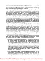
The example in Figure 8.4 shows a block diagram of an implementation of a
32-tap FIR filter. The shaded blocks are implemented in FPGA cells; the
unshaded blocks are implemented in ASIC cells. The RAM is much easier to
implement, and more efficient to implement, as a RAM cell than in an FPGA. By
implementing the address generator and ROM in FPGA cells, the algorithm can
easily be reprogrammed.
8.5 Summary
The latest programmable devices and future programmable devices hold great
promise for smaller chip designs, cost reductions, and increased flexibility. I’ve
given you my opinions about these devices. I may turn out to be wrong. Things
may change and by the time you read this, you may be seeing devices I haven’t
even predicted yet. “Core” technology, special I/O drivers, new architectures,
and ASICs embedded with FPGA cells all offer potential improvements in FPGA
and CPLD design. I can only leave you with the immortal words of the amazing
and mysterious Criswell from that unforgettable film, Plan Nine From Outer
Space, “We are all interested in the future, for that is where you and I are going
to spend the rest of our lives.”
Key
FPGA
ASIC
REG REG
REG
X
ADDRESS
GENERATOR
32x16
COEFFICIENT
ROM
ADDR ADDR
2Kx16
DUAL-PORT
RAM
DATA DATA
40-BIT
ACCUM.
REG
Figure 8.4 Mixed ASIC/FPGA design (copyright 2002, by Leopard Logic Corporation)
Please purchase PDF Split-Merge on www.verypdf.com to remove this watermark.
173
Appendix A
Answer Key
Chapter 1, “Prehistory: Programmable Logic to ASICs”
1. What does the term ASIC mean?
(c) Application Specific Integrated Circuit
2. Each programmable device is matched with its description in the following table.
a. PROM (A) A memory device that can be programmed once and read many
times.
b. PLA (D) A logic device with a large AND plane and a large OR plane for
implementing different combinations of Boolean logic.
c. PAL (E) A logic device with a large AND plane and a small, fixed number of
OR gates for implementing Boolean logic and state machines.
d. CPLD (C) A logic device that is made up of many PAL devices.
e. FPGA (B) A logic device that can be used to design large functions like an
ASIC except that it can be programmed quickly and inexpensively.
Please purchase PDF Split-Merge on www.verypdf.com to remove this watermark.
174 Appendix A: Answer Key
3. Listed is the correct device for each statement — PALs or ASICs.
(a) PALs have a short lead-time.
(b) ASICs are high-density devices.
(c) ASICs can implement very complex functions.
(d) PALs do not have NRE charges.
(e) PALs are programmable.
Chapter 2, “Complex Programmable Logic Devices (CPLDs)”
1. What does the term CPLD mean?
(a) Complex Programmable Logic Device
2. These are all of the parts of a typical CPLD.
(a) I/O Block
(d) Function Block
(e) Interconnect Matrix
3. Which technology is not used for CPLD programmable elements?
(d) DRAM
4. Which is not a characteristic of clock drivers
(c) Low power
5. The layout of traces that connects a clock driver to the flip-flops in a CPLD is called
(a) A clock tree
6. One advantage of the CPLD switch matrix routing scheme is that delays through the
chip are
(b) Deterministic
7. Embedded devices are (select one)
(b) Devices that are embedded inside a CPLD
Please purchase PDF Split-Merge on www.verypdf.com to remove this watermark.
Chapter 3, “Field Programmable Gate Arrays (FPGAs)” 175
Chapter 3, “Field Programmable Gate Arrays (FPGAs)”
1. What does the term FPGA mean?
(b) Field Programmable Gate Array
2. Here are all of the parts of a typical FPGA architecture.
(a) Configurable Logic Blocks
(c) Programmable Interconnect
(d) Configurable I/O Blocks
3. TRUE or FALSE is selected for the following statements.
(a) TRUE: Configurable I/O Blocks contain flip-flops on the inputs to enable a
designer to reduce the hold-time requirement for the inputs.
(b) TRUE: Configurable I/O Blocks contain flip-flops on the outputs to enable the
designer to decrease the clock-to-output times of the outputs.
(c) FALSE: FPGA programmable interconnect consists of lines that start at one end
of the chip and continue to the other end to enable all CLBs to be connected.
(d) TRUE: Programmable switches inside the chip allow the connection of CLBs to
interconnect lines
(e) TRUE: Programmable switches inside the chip allow the connection of intercon-
nect lines to each other and to the switch matrix.
(f) FALSE: Each flip-flop in an FPGA has its own unique clock line and clock buffer
to reduce skew.
(g) FALSE: Any input to an FPGA can be used for the clock input.
(h) FALSE: Antifuse FPGAs use an industry standard process.
(i) TRUE: Antifuse technology is faster than SRAM technology, in theory.
(j) TRUE: SRAM FPGAs are more common than antifuse FPGAs.
4. These are all potential advantages of embedded devices
(a) Reduced board area
(b) Reduced power consumption
(c) Reduced cost
(d) Increased system speed
(e) You don’t need to design and test the embedded device
Please purchase PDF Split-Merge on www.verypdf.com to remove this watermark.
176 Appendix A: Answer Key
5. TRUE or FALSE is selected for each of the following statements about SRAM-based
FPGAs and antifuse FPGAs.
(a) TRUE: SRAM-based FPGAs are based on an industry standard technology
(b) TRUE: In theory, SRAM-based FPGAs are much slower than antifuse FPGAs.
(c) TRUE: Antifuse FPGAs retain their programming after being powered off and
then on again.
(d) FALSE: Antifuse FPGAs can be erased and reprogrammed.
(e) TRUE: SRAM-based FPGAs can be erased and reprogrammed.
(f) FALSE: In practice, SRAM-based FPGAs are much slower than antifuse FPGAs.
(g) FALSE: SRAM-based FPGAs are programmed using high voltages.
(h) TRUE: Antifuse FPGAs are programmed using high voltages.
6. Clock trees are designed for (select one)
(c) Small delay and low skew
7. The following table shows the correct attributes of CPLDs and FPGAs.
Chapter 4, “Universal Design Methodology for Programmable
Devices”
1. The three major goals of UDM-PD are
(a) Design the device efficiently
(d) Design a device that works reliably over the lifetime of the device
(f) Plan the design efficiently
2. UDM is a methodology to design a device that
(a) Is free from manufacturing defects
(c) Functions correctly in your system
(d) Works reliably over the lifetime of the device
CPLD FPGA
Architecture
PAL-like Gate Array-like
Density
Low to medium Medium to high
Speed
Fast and predictable Application dependent
Interconnect
Crossbar Routing
Power consumption
High per gate Low per gate
Please purchase PDF Split-Merge on www.verypdf.com to remove this watermark.
Chapter 4, “Universal Design Methodology for Programmable Devices” 177
3. UDM is a methodology to design a device efficiently, meaning
(a) In the least amount of time
(b) Using the least number of people
(c) Using the least amount of resources
4. UDM is a methodology to plan a design efficiently, meaning
(b) Knowing all necessary resources up front and allocating them as early in the
process as possible
(c) Creating a reasonable schedule as early in the process as possible
5. Here is the design flow with each phase in the correct order.
(c) Write a specification
(e) Specification review
(g) Choose device and tools
(k) Design
(h) Simulate
(j) Design review
(l) Synthesis
(i) Place and route
(f) Resimulation
(d) Final review
(b System integration and test
(a) Ship product!
6. A design specification should include the following:
(b) A description of the I/O pins including output drive capabilities and input
threshold levels
(c) The estimated gate count
(d) The target power consumption
(e) Test procedures, including in-system test requirements
(f) An external block diagram showing how the FPGA fits into the system
(h) An internal block diagram showing each major functional section
(i) Timing estimates, including setup and hold times for input pins, propagation
times for output pins, and the clock cycle time
(j) The target price
(k) The package type
Please purchase PDF Split-Merge on www.verypdf.com to remove this watermark.
178 Appendix A: Answer Key
Chapter 5, “Design Techniques, Rules, and Guidelines”
1. The term HDL stands for
(a) Hardware description language
2. The model levels on the left are matched with the correct description on the right.
3. The following HDL levels are considered behavioral levels:
(b) Algorithmic level
(d) Architectural level
4. The following HDL levels are considered structural levels.
(a) Switch level
(c) Gate level
(e) Register transfer level
5. These are all of the statements that are true about top-down design.
(a) Allows better allocation of resources
(b) Allows each small function to be simulated independently
(c) Speeds up simulations
(d) Facilitates behavioral modeling of the device
(f) Allows a design to be split efficiently among the various team members
(a) Algorithmic A Describes a design in terms of mathematical func-
tionality.
(b) Architectural D Describes a design in terms of functional blocks.
(c) Register transfer level E Describes a design in terms of Boolean logic and
storage devices.
(d) Gate level B Describes a design in terms of basic logic such as
NANDs and NORs.
(e) Switch level C Describes a design in terms of transistors and basic
electronic components.
Please purchase PDF Split-Merge on www.verypdf.com to remove this watermark.
Chapter 5, “Design Techniques, Rules, and Guidelines” 179
6. The five rules of synchronous design are
(a) Data signals must go only to combinatorial logic or data inputs of flip-flops.
(b) All data is passed through combinatorial logic and flip-flops that are synchro-
nized to a single clock.
(c) Clocks cannot be gated — in other words, clocks must go directly to the clock
inputs of the flip-flops without going through any combinatorial logic.
(h) No signal that is generated by combinatorial logic can be fed back to the same
combinatorial logic without first going through a synchronizing flip-flop.
(i) Delay is always controlled by flip-flops, not combinatorial logic.
7. The asynchronous circuits on the left have been matched with the equivalent synchro-
nous circuits on the right.
8. TRUE or FALSE is selected for the following statements.
(a) FALSE: Synchronizing flip-flops are used to eliminate metastability.
(b) TRUE: In theory, a device can remain metastable forever.
(c) TRUE: The chances of a device going metastable increases with higher clock fre-
quencies.
(d) FALSE: The chances of a device going metastable decreases with higher input
voltage thresholds.
(e) FALSE: Schmidt trigger inputs with hysteresis can eliminate metastability.
(f) FALSE: Metastability is caused by faulty circuits.
(g) TRUE: Metastability is caused by asynchronous signals coming into synchro-
nous circuits.
9. These are all allowable uses of asynchronous logic.
(a) To latch inputs from and outputs to an asynchronous bus as long as the signals
are synchronized for use inside the design.
(c) Asynchronous reset if it is done according to specific rules.
(a) C
(b) D
(c) A
(d) B
Please purchase PDF Split-Merge on www.verypdf.com to remove this watermark.
180 Appendix A: Answer Key
10. TRUE or FALSE is selected for the following statements.
(a) TRUE: Floating buses can create signal noise.
(b) TRUE: Floating buses can cause extra power consumption.
(c) TRUE: Floating buses should be avoided in your design.
11. The following circuits avoid floating buses.
Circuits a, b, and c all avoid floating buses.
12. TRUE or FALSE is selected for the following statements.
(a) TRUE: Bus contention can reduce the reliability of your design over its lifetime.
(b) TRUE: Bus contention should be minimized if it can't be eliminated entirely.
13. Circuit b has the greatest potential for bus contention because nothing prevents both
drivers from being turned on at the same time.
14. Testability should be considered
(a) At the beginning of the design effort.
15. How many internal nodes in a design should be observable?
(d) As many as possible
16. Which one of these statements is true?
(c) Scan chain insertion effectively turns a sequential design into a combinatorial
design for testing purposes.
17. Which of the following structures is not required for BIST?
(c) Linear feedback shift register (LFSR)
18. The 10/10 rule of testing is:
(c) Testing circuitry should not up take more than 10 percent of the total circuitry
and should not require more than 10 percent of the design and debug time.
Chapter 6, “Verification”
1. What is meant by the term "functional simulation?"
(a) Simulating how a design functions, without regard to timing
Please purchase PDF Split-Merge on www.verypdf.com to remove this watermark.
Chapter 7, “Electronic Design Automation Tools” 181
2. What is meant by the term "toggle coverage?"
(b) The number of nodes in a design that change state from 0 to 1 and from 1 to 0
during simulation as a percentage of the total number of possible state transi-
tions.
3. What is meant by the term "code coverage?"
(c) The percentage of code statements in a design that have been executed during
simulation in every possible manner.
4. What is meant by the term "timing simulation?"
(b) A simulation that includes timing delays.
5. Why is timing simulation typically no longer done for a design?
(c) Static timing analysis is a faster, more exhaustive analysis of whether a design
meets its timing requirements.
6. What is meant by the term "static timing analysis?"
(a) A process that looks at a synchronous design and determines the highest operat-
ing frequency that does not violate any setup and hold-times.
7. What are the two types of formal verification?
(a) Functional verification and equivalency checking.
Chapter 7, “Electronic Design Automation Tools”
1. A testbench generator
(c) Generates simulation tests for your design from your high level description of
the test.
2. An in situ tool
(c) Allows a simulated, emulated, or prototype device to connect to a system and
communicate in real time.
3. Synthesis software
(d) Creates a low level design description from a functionally equivalent high level
design description.
4. ATPG stands for
(a) Automatic test pattern generation
Please purchase PDF Split-Merge on www.verypdf.com to remove this watermark.
182 Appendix A: Answer Key
5. BIST stands for
(d) Built-in self-test
6. Static timing analysis tools
(b) Analyze a design for all worst-case timing and determine whether the design
meets your timing requirements.
7. Place and route tools
(d) Both a and b (Create the bits that are used to program the device to implement
your design; and place the logic for your design in the programmable device and
connect that logic together)
8. TRUE or FALSE is given for the following statements:
(a) TRUE: Static timing analysis has replaced timing simulation for determining the
timing numbers for FPGA designs.
(b) FALSE: Dynamic timing analysis is a technique that will soon replace static tim-
ing analysis.
(c) FALSE: Scan insertion software is used to insert boundary scan chains into an
FPGA.
(d) FALSE: Formal verification is a mathematic method of assuring that a design
meets its timing requirements.
(e) TRUE: Floorplanning software allows you to place large chunks of your design
in specific locations on the chip.
(f) TRUE: SRAM-based FPGAs are programmed in the system.
(g) TRUE: Serial PROMs are often used to load a design into an SRAM-based
FPGA.
Please purchase PDF Split-Merge on www.verypdf.com to remove this watermark.
183
Appendix B
Verilog Code for
Schematics in Chapter 5
Listing B.1 Figure 5.2
/*********************************************************/
// MODULE: asynchronous race condition
//
// FILE NAME: arace.v
// VERSION: 1.0
// DATE: June 1, 2002
// AUTHOR: Bob Zeidman, Zeidman Consulting
//
// CODE TYPE: RTL
//
// DESCRIPTION: This module defines a circuit with an
// asynchronous race condition. Note that this circuit
// will simulate fine, but a synthesis program won't know
Please purchase PDF Split-Merge on www.verypdf.com to remove this watermark.
184 Appendix B: Verilog Code for Schematics in Chapter 5
// how to synthesize it into a synchronous circuit.
//
/*********************************************************/
// DEFINES
// TOP MODULE
module arace(
sig1,
sig2,
out);
// PARAMETERS
// INPUTS
input sig1; // data input
input sig2; // clock and clear input
// OUTPUTS
output out; // output
// INOUTS
// SIGNAL DECLARATIONS
wire sig1;
wire sig2;
reg out;
// ASSIGN STATEMENTS
// MAIN CODE
// Reset condition
always @(negedge sig2) out <= 0;
Listing B.1 Figure 5.2 (Continued)
Please purchase PDF Split-Merge on www.verypdf.com to remove this watermark.
Listing B.2: Figure 5.4 185
// Clocked condition
always @(posedge sig2) out <= sig1;
endmodule // arace
Listing B.1 Figure 5.2 (Continued)
Listing B.2 Figure 5.4
/*********************************************************/
// MODULE: no race condition
//
// FILE NAME: norace.v
// VERSION: 1.0
// DATE: June 1, 2002
// AUTHOR: Bob Zeidman, Zeidman Consulting
//
// CODE TYPE: RTL
//
// DESCRIPTION: This module defines a circuit without an
// asynchronous race condition.
//
/*********************************************************/
// DEFINES
// TOP MODULE
module norace(
clk,
sig1,
sig2,
out);
// PARAMETERS
// INPUTS
input clk; // system clock
input sig1; // data input
input sig2; // clock and clear input
Please purchase PDF Split-Merge on www.verypdf.com to remove this watermark.
186 Appendix B: Verilog Code for Schematics in Chapter 5
// OUTPUTS
output out; // output
// INOUTS
// SIGNAL DECLARATIONS
wire sig1;
wire sig2;
reg out;
reg state; // state variable
// ASSIGN STATEMENTS
// MAIN CODE
// Clocked condition
always @(posedge clk) begin
state <= sig2;
out <= (~state & sig1 & sig2) | (state & sig2 & out);
end
endmodule // norace
Listing B.2 Figure 5.4 (Continued)
Listing B.3 Figure 5.5
/*********************************************************/
// MODULE: delay dependent logic
//
// FILE NAME: ddl.v
// VERSION: 1.0
// DATE: June 1, 2002
// AUTHOR: Bob Zeidman, Zeidman Consulting
//
// CODE TYPE: RTL
//
Please purchase PDF Split-Merge on www.verypdf.com to remove this watermark.
Listing B.3: Figure 5.5 187
// DESCRIPTION: This module defines a circuit that creates
// a pulse whose width depends on circuit delay.
//
/*********************************************************/
// DEFINES
// TOP MODULE
module ddl(
a,
z);
// PARAMETERS
// INPUTS
input a; // input
// OUTPUTS
output z; // output
// INOUTS
// SIGNAL DECLARATIONS
wire a;
wire a1; // intermediate signal
wire a2; // intermediate signal
wire a3; // intermediate signal
wire z;
// ASSIGN STATEMENTS
assign a1 = ~a;
assign a2 = ~a1;
assign a3 = ~a2;
assign z = a3 & a;
Listing B.3 Figure 5.5 (Continued)
Please purchase PDF Split-Merge on www.verypdf.com to remove this watermark.
188 Appendix B: Verilog Code for Schematics in Chapter 5
// MAIN CODE
endmodule // ddl
Listing B.3 Figure 5.5 (Continued)
Listing B.4 Figure 5.6
/*********************************************************/
// MODULE: synchronous delay logic
//
// FILE NAME: sdl.v
// VERSION: 1.0
// DATE: June 1, 2002
// AUTHOR: Bob Zeidman, Zeidman Consulting
//
// CODE TYPE: RTL
//
// DESCRIPTION: This module defines a circuit that creates
// a pulse whose width depends on a clock signal.
//
/*********************************************************/
// DEFINES
// TOP MODULE
module sdl(
clk,
a,
z);
// PARAMETERS
// INPUTS
input clk; // system clock
input a; // input
Please purchase PDF Split-Merge on www.verypdf.com to remove this watermark.