Tài liệu Sổ tay RFID (P13) pptx
Bạn đang xem bản rút gọn của tài liệu. Xem và tải ngay bản đầy đủ của tài liệu tại đây (1.6 MB, 53 trang )
13
Example Applications
13.1 Contactless Smart Cards
The first plastic cards appeared in the USA as early as the beginning of the 1950s, when
cheap PVC replaced cardboard. In the years that followed, plastic credit cards became
widespread. Incidentally, the first credit card was issued by Diners Club in 1950.
The rapid development of semiconductor technology made it possible to integrate
data memory and protective logic onto a single silicon chip in the 1970s. The idea of
incorporating such an integrated memory chip into an identification card was patented
in 1968 by J
¨
urgen Dethloff and Helmut Gr
¨
otrupp in Germany. However, it was not until
almost 15 years later that the great breakthrough was achieved with the introduction
of the telephone smart card by the French company PTT. Several million telephone
smart cards were in circulation in France by 1986 (Rankl and Effing, 1996). These first
generation smart cards were memory cards with contacts. A significant improvement
was achieved when entire microprocessors were successfully integrated into a silicon
chip, a nd these chips incorporated into an identification card. This made it possible to
run software in a smart card, thus opening up the possibility of realising high-security
applications. Thus, smart cards for mobile telephones and the new bank cards (EC with
chip) were realised exclusively using microprocessor cards.
Since the mid-1980s, repeated attempts have been made to launch contactless smart
cards onto the market. The operating frequency of 135 kHz that was normal at the
time and the high power consumption of the silicon chips on the market necessitated
transponder coils with several hundred windings. The resulting large coil cross-section,
and the additional capacitors that were often required, impeded manufacture in the form
of ID-1 format plastic cards, and transponders were usually cast into inconvenient
plastic shells. Due to this limitation, contactless smart cards played a minor role in the
smart card market for a long time.
In the first half of the 1990s, transponder systems were developed with an operating
frequency of 13.56 MHz. The transponders required for these systems required just
five windings. For the first time it was possible to produce transponder systems in the
0.76 mm thick ID-1 format. The great breakthrough in Germany occurred in 1995, with
the introduction of the ‘Frequent Traveller’ contactless customer loyalty card in ID-1
format by the German company Lufthansa AG. It was noteworthy that these cards,
manufactured by the Munich company Giesecke & Devrient, still had a magnetic strip,
RFID Handbook: Fundamentals and Applications in Contactless Smart Cards and Identification,
Second Edition
Klaus Finkenzeller
Copyright
2003 John Wiley & Sons, Ltd.
ISBN: 0-470-84402-7
342 13 EXAMPLE APPLICATIONS
Memory
card
Chip card
ISO 7816
Processor
card
ID-1 Card
ISO 7810
Close cpl.
ISO 10536
Processor
card
Dual interface card
‘Combi Card’ I
Dual interface card
‘Combi Card’ II
Memory
card
Contactless
chip cards
Proximity
ISO 14443
Processor
card
Vicinity cpl.
ISO 15636
Memory
card
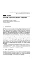
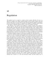
Figure 13.1 The large ‘family’ of smart cards, including the relevant ISO standard
a hologram and were embossed with the customer number and name. A more in-depth
description of this project is included in Section 13.3.
Today, contactless smart cards are divided into three groups based upon the applica-
ble standards (Figure 13.1): close coupling, remote coupling (inductively coupled) and
vicinity coupled (inductively coupled) smart cards. While vicinity coupling cards are
only available in the form of memory cards, microprocessor cards have been available
in the form of inductively coupled cards in small pilot projects since 1997.
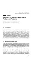
Currently, the main fields of application for contactless smart cards are payment
systems (public transport, ticketing) or passes (ID cards, company pass) (Figure 13.2).
In the long term we can e xpect that contactless smart cards will largely replace cards
with contacts in their classical fields of application (telephone cards, EC cards). In
addition, contactless technology will allow smart cards to be used in completely new
fields — fields we may not yet have even thought of.
13.2 Public Transport
Public transport is one of the applications where the greatest potential exists for the
use of RFID systems, particularly contactless smart cards. I n Europe and the USA
13.2 PUBLIC TRANSPORT 343
Philips semiconductors
M F, ##, //, ED, Rev. 0,
Market drivers
Banking
contact
(contactless)
Health care
Electronic
purse
Road toll
Park&ride
Public
Transport
contactless
Telecom
contact
(contactless)
EFTPOS
terminal
Credit card
Loyalty schemes
http://www.
xx.yy.at
GSM
Pay-TV
Geldkarte
Internet banking
Arline
ticketing
(AH)
ID-Card
University
Company
card
Pay-phone
Figure 13.2 The main fields of application for contactless smart cards are public transport and
change systems for telephone boxes or consumer goods (groceries, cigarettes) (reproduced by
permission of Philips Electronics N.V.)
traffic associations are still operating at a huge loss, sometimes as much as 40% of
turnover (Czako, 1997), which must be made up by subsidies from the community and
country in question. Due to the increasing shortage of resources, long-term solutions
must be sought that will cut these losses by reducing costs and increasing income.
The use of contactless smart cards as electronic travel passes could make an important
contribution to improving the situation (AFC = automatic fare collection). In the field
of fare management in particular there is a great deal of room for improvement.
13.2.1 The starting point
The unhealthy financial situation of transport companies naturally has many differ-
ent causes. However, the following factors are worth mentioning in connection with
electronic travel passes:
• Transport companies incur high costs through the sale of travel passes by automatic
dispensers. For example, the sale of a travel pass through an automatic dispenser
in Z
¨
urich costs Sfr 0.45, where the average sales price is Sfr. 2.80 (Czako, 1997).
Thus, 16% of the sales price is lost from the outset by the provision of the dis-
penser, maintenance and repairs alone (filling with notes and c oins, r epairs, damage
by vandalism).
• In vehicles, too, expensive electronic ticket printers or mobile devices are required.
Sometimes the tickets are even sold by the driver, which causes long waiting times
344 13 EXAMPLE APPLICATIONS
while passengers board, plus the additional security risk presented by the continuous
distraction of the driver.
• Paper tickets are thrown away after use, although the manufacture of fraud-proof
tickets for transport companies is becoming more and more expensive.
• In German cities in particular, losses of up to 25% must be taken into account due
to fare-dodgers (Czako, 1997). This is because German transport companies have
very liberal travelling conditions and permit entry to the underground system and
buses without travel passes first being checked.
• Association discounts can only be calculated on the basis of costly random counts,
which leads to imprecision in the calculation.
13.2.2 Requirements
Electronic fare management systems have to fulfil very high expectations and require-
ments, particularly with regard to resistance to degradation a nd wear, write and read
speed and ease of use. These expectations can only be satisfactorily fulfilled by RFID
systems. The most common format for contactless smart cards is the ID-1 format and,
recently, wrist watches.
13.2.2.1 Transaction time
The time taken for the purchase or verification of a travel pass is particularly critical
in transport systems in which the pass can only be checked inside the vehicle. This
is a particular problem in buses and trams. In the underground railway, passes can be
checked at a turnstile, or by conductors. A comparison of different methods shows the
clear superiority of RFID systems in terms of transaction times (Table 13.1).
13.2.2.2 Resistance to degradation, lifetime, convenience
Contactless smart cards are designed for a lifetime of 10 years. Rain, cold, dirt and
dust are a problem for neither the smart card nor the reader.
Table 13.1 Passenger processing times for different tech-
nologies. Source: transport companies in Helsinki, taken from
Czako (1997)
Technology Passenger processing time
(s)
RFID I (remote coupling) 1.7
Visual verification by driver 2.0
RFID II (close coupling) 2.5
Smart card with contacts 3.5
Cash >6
13.2 PUBLIC TRANSPORT 345
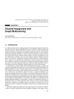
Figure 13.3 Contactless reader in a public transport system (photo: Frydek-Mistek project,
Czechoslovakia, source: reproduced by permission of EM Test)
Contactless smart cards can be kept in a briefcase or handbag and are therefore
extremely convenient to use (Figure 13.3). Transponders can also be fitted into wrist-
watches.
13.2.3 Benefits of RFID systems
The replacement of conventional paper tickets by a modern electronic fare management
system based on contactless smart cards provides a multitude of benefits to all those
involved. Although the purchase costs of a contactless smart card system are still
higher than those of a conventional system, the investment should repay itself within a
short period. The superiority of contactless systems is demonstrated by the following
benefits for users and operators of public transport companies.
Benefits for passengers
• Cash is no longer necessary, contactless smart cards can be loaded with large
amounts of money, passengers no longer need to carry the correct change.
• Prepaid contactless smart cards remain valid even if fares are changed.
• The passenger no longer needs to know the precise fare; the system automatically
deducts the correct fare from the card.
346 13 EXAMPLE APPLICATIONS
• Monthly tickets can begin on any day of the month. The period of validity begins
after the first deduction from the contactless card.
Benefits for the driver
• Passes are no longer sold, resulting in less distraction of driving staff.
• No cash in vehicle.
• Elimination of the daily income calculation.
Benefits for the transport company
• Reduction in operating and maintenance costs of sales dispensers and ticket
devaluers.
• Very secure against vandalism (chewing gum effect).
• It is easy to change fares; no new tickets need to be printed.
• The introduction of a closed (electronic) system, in which all passengers must
produce a valid travel pass, can significantly reduce the number of f are dodgers.
Benefits for the transport association
• It is possible to calculate the performance of individual partners in the associa-
tion. Because precise data is obtained automatically in electronic fare management
systems, the discount for the association can be calculated using precise figures.
• Expressive statistical data is obtained.
Benefits for the treasury
• Reduction of the need for subsidies due to cost reductions.
• Better use of public transport due to the improved service has a positive effect on
takings and on the environment.
13.2.4 Fare systems using electronic payment
Transport association regions are often divided into different fare zones and pay-
ment zones. There are also different types of travel pass, time zones and numerous
possible combinations. The calculation of the fare can therefore be extremely compli-
cated in conventional payment systems and can even be a source of bewilderment to
local customers.
Electronic fare management systems, on the other hand, facilitate the use of com-
pletely new procedures for the calculation and payment of fares. There are four basic
models for electronic fare calculation, as shown in Table 13.2.
13.2.5 Market potential
It is estimated that around 50% of all contactless cards sold are used in the public
transport sector (Hamann, 1997). The biggest areas of use are the large population
13.2 PUBLIC TRANSPORT 347
Table 13.2 Different fare systems for p ayment with contactless smart card
Fare system 1 Payment takes place at the beginning of the journey. A fixed amount is
deducted from the contactless smart card, regardless of the distance
travelled.
Fare system 2 At the beginning of the journey the entry point (check-in) is recorded on the
contactless card. Upon disembarking at the final station (check-out), the
fare for the distance travelled is automatically calculated and deducted
from the card. In addition, the card can be checked at each change-over
point for the existence of a valid ‘check-in’ entry. To foil attempts at
manipulation, the lack of a ‘check-out’ record can be penalised by the
deduction of the maximum fare at the beginning of the next journey.
Fare system 3 This model is best suited for interlinked networks, in which t he same route
can be travelled using different transport systems at different fares. Every
time the passenger changes vehicles a predetermined amount is deducted
from the card, bonus fares for long distance travellers and people who
change several times can be automatically taken into account (see
Figure 13.4).
Best price
calculation
In this system all journeys made are recorded on the contactless card for a
month. If a certain number of journeys was exceeded on one day o r in
the month as a whole, then the contactless card can automatically be
converted into a cheaper 24 hour or monthly card. This gives the
customer maximum flexibility and the best possible fares. Best price
calculation improves customer relations and makes a big contribution to
customer satisfaction.
centres in Asia (Seoul, Hong Kong, Singapore, Shanghai), and European cities (Paris,
London, Berlin).
In 1994 and 1995 around 1 million contactless smart cards were produced per year
worldwide for public transport applications. In the period 1996 to 1997 the volume
rose to over 40 million cards per year (Droschl, 1997). The expected volume for 1998
alone is around 100 million contactless smart cards worldwide for public transport
applications (Hamann, 1997). Given annual growth rates of 60% or more, we can
expect the annual demand for contactless smart cards to have risen to 250 million by
the turn of the century.
The highest growth rates for contactless smart cards in public transport applications
will be in the Asiatic-Pacific area, because of the new infrastructures being created
here using the latest technologies (Droschl, 1997).
13.2.6 Example projects
13.2.6.1 Korea – Seoul
The largest electronic travel pass system (AFC) yet to use contactless cards was
commissioned at the start of 1996 in the metropolis of Seoul, South Korea (see
Figures 13.5–13.7). The Korean ‘Bus Card’ is a prepaid c ard, issued with a basic
value of 20 000 W− (∼17 euro). Fares are calculated according to fare system 1. A bus
journey costs an average of 400 W− (∼0.35 euro), but every time the passenger changes
vehicles they must pay again.
348 13 EXAMPLE APPLICATIONS
Bus 1
Fare system 1
Fare system 2
Fare system 3
Entrance, change of vehicle, final station
Read/write to contactless cards
Under-
ground
Bus 2
Figure 13.4 Use of the different tariff systems in a journey by public transport. The journey
shown involves two changes between the underground and bus network. The number of times
the smart card is read depends upon the fare system used
Figure 13.5 Use of a contactless smart card in Seoul. A contactless terminal is shown in com-
munication with a contactless smart card in the centre o f the picture (reproduced by permission
of Intec)
The card can be used on all 453 lines and recharged at identified kiosks as required.
The transport association, Seoul Bus Union, is made up of 89 individual operator
companies with a total of over 8700 buses, which were all equipped with contactless
terminals by the middle of 1996. When the Kyung-Ki province that surrounds the cap-
ital city was included in the scheme, a further 4000 buses and a total of 3500 charging
points were fi tted with terminals by 1997 (Droschl, 1997). The RFID technology used
in this project is the MIFARE
system (inductively coupled, 10 cm, 13.56 MHz), which
is very popular in public transport applications.
It is predicted that four million Bus Cards will be in circulation by the end of 1997.
The huge success of this system has convinced the government of Seoul to introduce
a compatible system for the underground railway system.
13.2 PUBLIC TRANSPORT 349
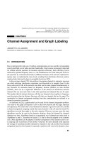
Figure 13.6 Contactless smart card for paying for journeys in a scheduled bus in Seoul (repro-
duced by permission of Klaus Finkenzeller, Munich)
Figure 13.7 Reader for contactless smart cards at the entrance of a scheduled bus in Seoul
(reproduced by permission of Klaus Finkenzeller, Munich)
13.2.6.2 Germany – L
¨
uneburg, Oldenburg
One of the first smart card projects in Germany’s public transport system is the Fahrs-
mart project in the KVG L
¨
uneburg — VWG Oldenburg transport association. The
subsidised Fahrsmart pilot project was launched by the Ministry for Education and
Research in this area as early as 1990/91. Around 20 000 smart cards with contacts
350 13 EXAMPLE APPLICATIONS
were issued to customers for this project. However, significant flaws in the installed
systems became evident during this pilot project; the biggest problem was that the
registration time of over three seconds per passenger was considered to be excessive.
At the beginning of 1996 a new field test was launched, the Fahrsmart II system
based upon contactless smart cards. The RFID technology used was the MIFARE
system by Philips/Mikron. System integration, i.e. the commissioning of the entire
system, was performed by Siemens VT (Berlin).
The Fahrsmart system automatically calculates the c heapest price for the customer
(best price guarantee). The passenger must check in at the start of the journey using
their personal smart card and check out at the end of the journey. The journey data
obtained are collected in the on-board computer and stored on the smart card for
verification.
When the vehicle returns to the depot at the end of the day the current day’s
data is sent from the vehicle computer to the station server via an infrared interface
(Figure 13.8). The processed data is then transferred to the central Fahrsmart server via
an internal network. To calculate the monthly invoice, the Fahrsmart server analyses
the usage profile of each individual passenger and calculates the cheapest ticket for
the distance travelled (individual journey, weekly pass, monthly pass etc.). Figure 13.9
shows a Fahrsmart II smart card.
13.2.6.3 EU Projects – ICARE and CALYPSO
Some of the above-mentioned local transport projects using contactless smart cards,
like almost all projects realised to date, are so-called closed exchange systems. In
practice this means that the smart cards are ‘charged up’ with money, but can only be
used within the public transport system in question as a ticket or means of payment
for small amounts — for example in the operating company’s drinks machines. They
cannot be used in other shops or even as an electronic travel pass in other towns.
IR moduleIR module
On-board
computer
Contactless
card reader
Vehicle equipment
Depot
server
Fahrsmart
server
Depot signal
Depot/headquarters
Customer service
reader
Figure 13.8 System components of the Fahrsmart system. The vehicle equipment consists of
a reader for contactless smart cards, which is linked to the on-board computer. Upon entry into
the station, the record data is transferred from the on-board computer to a depot server via an
infrared link
13.2 PUBLIC TRANSPORT 351
Figure 13.9 Fahrsmart II contactless smart card, partially cut away. The transponder coil is
clearly visible at the lower right-hand edge of the picture (reproduced by permission of Giesecke
& Devrient, Munich)
This means that the card holder has to store money for a specific application in the
electronic purse of each closed system and no longer has direct access to this for a
different application (e.g. telephone smart card, contactless travel pass, prepaid card
for the company r estaurant) (Lorenz, 1998b).
This is the result of the card technology used, since the cards that have predominated
up until now have only a memory chip and thus do not satisfy the strict security
requirements of the credit institutes for open automated financial exchange systems.
Open financial exchange systems based upon a microprocessor chip have already
been successfully introduced in the field of contact smart cards. In Germany these
systems a re the Paycard from Telekom, the VISA-Cash-Karte, and the ‘ec-Karte mit
Chip’, the latter having the greatest c ustomer base with approximately 50–55 million
cards in use. These c ards were designed for payments of small sums and can be used
everywhere that suitable readers are available. From the point of view of the user, it
would be ideal if the cash card could be used as a ticket for local public transport. Due
to the high transaction times of contact smart cards (see Section 13.2.2.1) electronic
cash cards have also not yet been able to establish themselves as an electronic travel
pass in local public transport applications.
Various solutions have been proposed that aim to combine the user-friendliness of
contactless tickets with the security of contact exchange systems, and thus improve the
acceptance of such systems by customers (Lorenz, 1998b).
The hybrid card is the combination of a contactless smart card with an additional
contact chip on one card. There is, however, no electrical connection between the two
chips. This means that it must be possible to transfer sums of money from one chip to
the other — for example in special machines. Due to this limitation, the hybrid card
too can only be considered as a provisional solution.
The dual interface card (or Combicard, see Section 10.2.1) resulted from the combi-
nation of a contact and a contactless interface on a single card chip. This is actually the
352 13 EXAMPLE APPLICATIONS
ideal solution for the combination of an electronic travel pass with an open financial
exchange system. However, the question of when the electronic purse of the German
ZKA (ec-card) will be available as a dual interface card, and what quantities will exist,
must remain unanswered for the present. However, VISA has already announced that
it will integrate its VISA cash chip, previously based upon contact technology, into a
combichipinMadrid.
The envelope solution, in which a contactless ‘adapter’ turns the contact smart card
into a contactless pass, offers the advantage over the above-mentioned variants that the
microprocessor smart cards already in circulation can be made usable as contactless
cards without changing the cards themselves (Figure 13.10).
The envelope solution is central to ICARE (‘Integration of contactless technologies
into public transport environment’). This EU-supported project is oriented towards
the use of open electronic exchange systems in local public transport systems
(Lorenz, 1998a). The field trials for this project, which was started as early as 1996,
will be performed in various European regions.
In Paris, the largest European conurbation, 40 000 RATP staff and 4000 passengers
have already been equipped with an envelope. As an additional feature, an emer-
gency call feature has been developed that is currently being tested in the metro.
This feature can be triggered by means of the envelope. In addition to the enve-
lope concept, the development of a disposable ticket was also given some priority
in Paris.
In Venice, a town with a high proportion of day trippers, several landing stages
have been fitted with contactless readers. In addition to the contactless ticket function,
a central feature in Venice is the multifunctionality of the concept. The card can be
used in museums, hotels, or as a car park ticket. In the district of Constance on Lake
Constance, after an initial field trial in Autumn 1996, a second field trial was initiated
Figure 13.10 The contactless FlexPass of the district of Constance showing the GeldKarte and
envelope (reproduced by permission of TCAC GmbH, Dresden)
13.2 PUBLIC TRANSPORT 353
in January 1998. In this second trial the cashcard of the local savings bank is used in
conjunction with an envelope to form the ‘FlexPass’ (Lorenz, 1998b), which can be
used in local transport (Figure 13.11).
A hands-free antenna with a range of 1 m allows statistical data on card use to be
recorded without the customer having to hold the envelope near to the reader.
In Lisbon, a medium-sized European capital city with a complex local public trans-
port system and numerous public and private operating companies, the development
of a handsfree a ntenna was also central to the project.
Since 1998, research activities have been continued under the EU CALYPSO project
(‘Contact And contactLess environments Yielding a citizen Pass integrating urban Ser-
vices a nd financial Operations’). Transport companies have increased their efforts to
build up a partnership with the operators of automated exchange systems. Among other
companies from the German credit industry, the Deutsche Sparkassen- und Giroverband
(DSGV) has been recruited as a partner (Amp
´
elas, 1998; Lorenz, 1998c).
The objective of the CALYPSO project is the ‘FlexPass’. The intention is that this
will replace both the paper ticket and the cash used by the customer for payment. A
new aspect of the project is the introduction of further services on the envelope, for
example a dynamic passenger information service, i.e. departure times and connections
Figure 13.11 Contactless transaction using the FlexPass at a reader (reproduced by permission
of TCAC GmbH, Dresden)
354 13 EXAMPLE APPLICATIONS
are shown on the display. Use in car parks or the integration of (emergency) call
services is also being considered.
In the long term, the inclusion of further applications in the fields of parking, tourism,
public administration, or even car-sharing on the FlexPass is planned (Lorenz, 1998c).
13.3 Ticketing
13.3.1 Lufthansa miles & more card
The Lufthansa ‘Ticketless flying’ project is the German showcase project f or contactless
smart card systems. The pilot test involving 600 regular fliers from May to December
1995 ran so smoothly that by March 1996 the ‘Miles & More’ programme was extended
to all Lufthansa cards (‘HON Club’, ‘SENATOR’ and ‘Frequent Traveller’), and the
Lufthansa owned service company AirPlus was established. Since Autumn 1996, all
of the approximately 250 000 regular fliers possess the new contactless ‘ChipCard’.
This new contactless smart card — in conjunction with the Lufthansa central com-
puter in Munich-Erding — replaces both the old paper ticket and the conventional
boarding pass.
The RFID system selected for this project was the MIFARE
system by Philips/
Mikron. The terminals were developed by Siemens-Nixdorf, while the contactless smart
cards were manufactured by the Munich company Giesecke & Devrient. In addition
to a contactless transponder module, the cards also incorporate a magnetic strip, raised
lettering, signature strip, hologram and an optional (contact based) telephone chip
(Figure 13.12).
From the point of view of the passenger, the system operates as follows: the card
holder books a flight by telephone via a travel agent, quoting his individual card
Figure 13.12 Miles & More — Senator ChipCard, partially cut away. The transponder module
and antenna are clearly visible at the right-hand edge of the picture underneath the hologram
(reproduced by permission of Giesecke & Devrient, Munich)
13.3 TICKETING 355
Figure 13.13 Passenger checking in using the contactless Miles & More Frequent Flyer Card
(reproduced by permission of Lufthansa)
number. With the new cards, the booking may be performed up to one hour before
departure. An electronic ticket is created that combines personal data a nd the flight
data, and this is saved in the Lufthansa computer. To check in at the airport (at the last
minute) the smart card owner only has to present his contactless smart card briefly at
the Chip-In-Terminal (Figure 13.13). Normally, he can do this without even removing
the card from his briefcase. The system verifies the booking, and the flight data appear
on the screen. At this point the passenger is given the option of either confirming the
suggested flight including seat reservation or selecting an alternative flight on the touch
screen monitor. The passenger receives a printed receipt specifying his seat number
and boarding gate, plus other details. This procedure allows the passenger to check in
with his hand luggage in less than 10 seconds, which helps to prevent queues at the
terminal. When he arrives at the boarding gate he merely presents his ChipCard once
again and can then board.
The new ChipCard solution benefits both passengers and Lufthansa and AirPlus.
The passengers are overjoyed about the time saving on the ground, the ability to
book at short notice and the convenient and simple operation. Clear rationalisation
356 13 EXAMPLE APPLICATIONS
successes can be seen at Lufthansa and AirPlus, above all due to the self service
of customers, which significantly reduces labour intensive handling and verification
tasks. Furthermore, the ability to accept short notice bookings is increased by the
time saving on the ground, thus increasing competitiveness compared to alternative
travelling options (according to Giesecke & Devrient, 1997).
13.3.2 Ski tickets
Anyone entering a ski lift has to be in possession of a valid daily or weekly pass. These
tickets were originally made of cardboard and validated by a date stamp. Checking
paper tickets is very labour intensive because each ticket must be checked visually for
validity. Furthermore, it is inconvenient for individual skiers to have to fish around in
their anoraks for a sodden paper ticket with cold fingers before every journey on the lift.
RFID technology offers an ideal alternative by replacing paper tickets with contact-
less smart cards or disk transponders (Figure 13.14). When the transponder is sold a
deposit of 5–10 euros is usually retained. After use, the transponder can be returned
and the deposit refunded. The lift operator c an revalue the transponder using special
readers a nd it can thus be reused.
The read range of the system is designed to be great enough that the transponder
tickets no longer need to be held in the hand, but can remain in an anorak pocket.
All ski lift entrances are protected by a turnstile, which is released by the read elec-
tronics upon detection of a valid transponder. In order to read the skier’s transponder,
however it is carried, e very entrance is monitored by two antenna opposite each other.
The size of the magnetic antenna is a problem, because it must be very large
due to the desired read range. The resulting magnetic coupling between the two reader
antennas is so great at a distance of several metres that the resulting mutual interference
makes it impossible to read a transponder. To circumvent this problem, ski ticket
Figure 13.14 Contactless reader as access control and till device at a ski lift (reproduced by
permission of Legic Identsystems, CH-Wetzikon)
13.4 ACCESS CONTROL 357
Release signal
Control unit
HF-enable
Turnstile
Reader 1
Entrance
Entrance
MUX
Busy signal
Reader 2
Reader 3
Reader 4
Figure 13.15 To achieve mutual decoupling the readers are switched alternately in time-
division multiplex operation
systems activate only one reader at a time, while the HF field of all other readers is
switched off altogether. To achieve this, a multiplexer sends a start signal to one reader
after the other in a cyclical sequence, which causes the addressed reader to switch on
its HF field and check for the presence of a transponder (Figure 13.15). If the reader
discovers a transponder, then it activates a busy signal. The busy signal tells the control
unit to suppress the cyclical start signal for the duration of the busy signal. The active
reader is now free to perform the data exchange it has begun with the transponder.
After the end of this transaction, the active reader stops transmitting the busy signal,
whereupon the multiplexer can continue its cyclical interrogation.
13.4 Access Control
Electronic access control systems using data carriers are used to automatically check
the access authorisation of individuals to buildings, (commercial or event) premises,
or individual rooms. When designing such systems we must first differentiate between
two fundamentally different systems with corresponding properties: online and offline
systems.
13.4.1 Online systems
Online systems tend to be used where the access authorization of a large number
of people has to be checked at just a few entrances. This is the case, for example,
at the main entrances to office buildings and commercial premises. In this type of
system, all terminals are connected to a central computer by means of a network.
358 13 EXAMPLE APPLICATIONS
The central computer runs a database in which each terminal is assigned all the data
carriers authorised for access to that terminal. The authorisation data generated from
the database is loaded into the terminals (or into an intermediate door control unit) via
the network and saved there in a table.
Changes to an individual’s access authorisation can be made by a single entry on
the central computer of the access control system. The data carrier itself does not need
to be present, since only an entry in the central database has to be edited. This is
advantageous, because it means that sensitive security areas can be protected against
unauthorised access even in the event of a data carrier being lost.
The data carriers of an online system only have to be able to store a small amount
of data, f or example a unique pass number. The use of read-only transponders is also
possible. See Figure 13.16.
13.4.2 Offline systems
Offline systems have become prevalent primarily in situations where many individual
rooms, to which only a few people have access, are to be equipped with an electronic
access control system. Each terminal saves a list of key identifiers (e.g. general-key-3,
floor-waiter-7, guest-room-517), for which access to this terminal is to be authorised.
There is no network to other terminals or a central computer.
Information regarding the rooms to which the data carrier can provide access is
stored on the data carrier itself in the form of a table of key identifiers (e.g. ‘guest-
room-517’, ‘sauna’, ‘fitness-room’). The terminal compares all the key identifiers stored
on a data carrier with those stored in its own list and permits access as soon as a
match is found. The transponder is programmed at a central programming station,
for example at the reception of a hotel upon the arrival of the guest. In addition to
the authorised rooms, the transponder can also be programmed with the duration of
validity, so that hotel keys, for example, are automatically invalidated on the departure
date of the guest.
Figure 13.16 Access control and time keeping are combined in a single terminal. The watch
with an integral transponder performs the function of a contactless data carrier (reproduced by
permission of Legic
-Installation, Kaba Security Locking Systems AG, CH-Wetzikon)
13.4 ACCESS CONTROL 359
Figure 13.17 Offline terminal integrated into a doorplate. The lock is released by holding the
authorized transponder in front of it. The door can then be opened by operating the handle. The
door terminal can be operated for a year with four 1.5 V Mignon batteries and even has a real
time clock that allows it to check the period of validity of the programmed data carrier. The
terminals themselves are programmed by an infrared d ata transmission using a portable infrared
reader (reproduced by permission of H
¨
afele GmbH, D-Nagold)
Only in the event of a data carrier being lost do key identifiers need to be deleted
from the terminal in question using a suitable programming device.
Offline systems offer the f ollowing advantages over conventional lock systems with
key and cylinder (Koch and Gaur, 1998) (see Figures 13.17 and 13.18):
• Early specification on a lock plan in the normal sense is not necessary. The system
is initially coded for use as a building-site. When the site is handed over, the
door terminals are recoded for commercial use by means of an infrared interface.
Subsequent changes and expansions do not pose any problems.
• The option of programming time windows opens up further options: Temporary
employees can receive a ‘three-month key’, the data carriers of cleaning staff can
be given precise time specifications (for example Mondays and Fridays from 17.30
to 20.00).
• The loss of a key causes no problems. The data of the lost key is deleted from
the read stations, a new key is programmed, and this key’s data is entered on the
terminals in question.
360 13 EXAMPLE APPLICATIONS
Figure 13.18 The hotel safe with integral offline terminal can only be opened by an authorised
data carrier (reproduced by permission of (hotel-save is shown by t he picture) H
¨
afele GmbH,
D-Nagold)
13.4.3 Transponders
Access control using PVC cards has been around for a long time. Hole punched cards
were used initially, which were superseded by infrared passes (IR barcode), mag-
netic strip passes, Wiegand passes (magnetic metal strips), and finally smart cards
incorporating a microchip (Schmidh
¨
ausler, 1995; Virnich and Posten, 1992). The main
disadvantage of these procedures is the inconvenience of the operating procedure due
to the fact that the cards must always be inserted into a reader the right way round.
Access control using contactless systems permits much greater flexibility because the
transponder only needs to pass a short distance from the reader antenna. Passes can be
made in the form of contactless smart cards, key rings, and even wristwatches.
A great advantage of contactless access control systems is that the reader is mainte-
nance-free and is not influenced by dust, dirt or moisture. The antenna can be mounted
‘under plaster’, where it is completely invisible and protected against vandalism. Hands-
free readers are also available for mounting in turnstiles or to increase convenience.
In these designs, the transponders do not even need to be removed from the pocket or
jacket clip.
Cat flaps operated by a transponder in the cat’s collar represent another application
in the field of access control, as does the use of read-only transponders as anti-theft
sensors for opening or closing doors and windows (Miehling, 1996).
13.5 TRANSPORT SYSTEMS 361
13.5 Transport Systems
13.5.1 Eurobalise S21
Although Europe is moving closer together cross-border transport still presents an
obstacle to Europe’s railways. Different signals and train security systems force trains to
incur the cost of carrying multiple sets of equipment on locomotives and tractive units.
It is often necessary to expend precious time changing tractive vehicles at the border,
burdening trains with a competitive disadvantage compared to flying or travelling by
road (Lehmann, 1996).
For this reason, the European Union is backing the purchase of a unified European
train security and control system, the ETCS (European Train Control System). The
ETCS will facilitate interoperable cross-border traffic and improve the competitiveness
of railways by implementing the latest train control technology.
The ETCS comprises four main systems:
• EURO-Cab A vehicle device, in which all connected elements are linked to
the secure vehicle computer EVC (European Vital Computer) by a special ETCS
bus system.
• EURO-Radio A GSM radio link between the vehicles a nd a radio centre by the
track, the RBC (Radio Block Center).
• EURO-Loop A system for linear data transfer over distances up to several hundred
metres. The system is based upon so-calle d leakage cable, i.e. coaxial cables for
which the sheathing is designed to be partially permeable to the electromagnetic
field. The frequency ranges of this application lie between around 80 MHz a nd
1 GHz (Ernst, 1996). EURO-Loop is primarily used to transfer information for the
evaluation of discretely transmitted data.
• EURO-Balise A system for the discrete transmission of data. Depending upon
design, local data (location marking, gradient profiles, speed limits) or signal-related
data for the route are transmitted to the vehicle (Lehmann, 1996).
The Eurobalise subsystem is particularly important, because it is a crucial prerequi-
site for the full introduction of the ETCS. In January 1995, after lengthy experiments,
the technical framework data for the EURO-Balise were determined. It is an inductively
coupled RFID system with anharmonic feedback frequency.
The power supply to the system is taken from a passing tractive unit by inductive
coupling a t the ISM frequency 27.115 MHz. Data is transferred to the tractive unit a t
4.24 MHz, and the system is designed to reliably read the data telegram at train speeds
of up to 500 km/h. See Figures 13.19 and 13.20, and Table 13.3.
Four different balise types have been developed by Siemens:
• Type 1 transmits a permanently programmed telegram.
• Type 2 transmits a telegram that can be programmed by the user via the contactless
interface. For example, this may be line data such as gradient and speed profiles.
362 13 EXAMPLE APPLICATIONS
Figure 13.19 Euro balise in practical operation (reproduced by permission of Siemens Verke-
hrstechnik, Braunschweig)
Figure 13.20 Fitting a read antenna for the Euro balise onto a tractive unit (reproduced by
permission of Siemens Verkehrstechnik, Braunschweig)
13.5 TRANSPORT SYSTEMS 363
Table 13.3 Basic data for the Eurobalise
Coupling Inductive
Power transmission frequency, vehicle → balise 27.115 MHz
Data transmission frequency, balise → vehicle 4.24 MHz
Modulation type FSK
Modulation index 1
Data rate 565 Kbit/s
Telegram length 1023 or 341-bit
Useful data size 863 or 216-bit
Read distance 230 to 450 mm
Maximum sideways offset 180 mm
Coverage with snow, water, ore Non-critical
• Type 3 transmits a telegram generated by a line device (transparent balise). Type 3
is primarily used in connection with signals.
• Type 4 makes it possible to download data as vehicles drive past.
13.5.2 International container transport
International freight transport containers have been identified using the alphanumeric
identification procedure specified in the international standard ISO 6346 since the end
of the 1960s. This identification mark consists of four letters, the owner’s code, a
six-digit numeric serial number and a test digit, and is painted onto the outside of the
container at a specified position (Figure 13.21).
Almost all of the 7 million containers in use worldwide employ the identification
procedures specified in this standard and thus have their own, unmistakable identifi-
cation number. The process of manually recording the container identification number
and entering it into the computer of a transhipment plant is extremely susceptible to
errors. Up to 30% of identifications have been falsely recorded at some point. Auto-
matic data transmission can help to solve this problem by the reading of a transponder
attached to the container. In 1991 the international standard ISO 10374 was drawn up
to provide a basis for the worldwide use of this technology.
The bands 888 to 889 MHz and 902 to 928 MHz (North America) and 2.4 to 2.5 GHz
(Europe) are used as the operating frequencies for the transponders. The transponders
must respond on all three of the frequency ranges used. Backscatter modulation (mod-
ulated reflection c ross-section) with an FSK modulated subcarrier is the procedure used
for the data transfer from the container to the reader. The subcarrier frequencies a re
20 kHz and 40 kHz. A total of 128 bits (16 bytes) are transmitted within just 2 ms.
Figure 13.21 Container identification mark, consisting of owner’s code, serial number and a
test digit
364 13 EXAMPLE APPLICATIONS
The reader’s signal is not modulated (read-only transponder). The specified maxi-
mum reader distance is 13 m.
ISO 10374 specifies the following information that can be stored in the transponder:
• owner’s code, serial number and test digit;
• container length, height and width;
• container type, i.e. suitcase container, tank container, open top container and others;
• laden and tare weight.
A battery provides the power supply to the electronic data carrier in the transponder
(active transponder). The lifetime of the battery corresponds with the lifetime of the
container itself, i.e. around 10 to 15 years.
The same technology is used in the identification of goods wagons in North Amer-
ican and European railway transport. A European standard is in preparation for the
automatic identification of European interchangeable containers (Siedelmann, 1997).
13.6 Animal Identification
13.6.1 Stock keeping
Electronic identification systems have been used in stock keeping for almost 20 years
(Kern and Wendl, 1997) and are now state of the art in Europe. In a ddition to inter-
nal applications for automatic feeding and calculating productivity, these systems can
also be used in inter-company identification, for the control of epidemics and quality
assurance and for tracing the origin of animals. The required unified data transmission
and coding procedures are provided by the 1996 ISO standards 11784 and 11785 (see
Section 9.1). The specified frequency is 134.2 kHz, and FDX a nd SEQ transponders can
both be used. A size comparison of the various transponders is given in Figure 13.22.
There are four basic procedures for a ttaching the transponder to the animal:
collar transponders, ear tag transponders, injectible transponders and the so-called
bolus (Figure 13.23). Cross-sections of different types of transponders are shown in
Figure 13.24.
Collar transponders can be easily transferred from one animal to another. This
permits the use of this system within a company. Possible applications are automatic
feeding in a feeding stall and measuring milk output.
Ear tags incorporating an RFID transponder compete with the much cheaper bar-
code ear tags. However, the latter are not suitable for total automation, because barcode
ear tags must be passed a few centimetres from a hand reader to identify the animal.
RFID ear tags, on the other hand, can be read at a distance of up to 1 m.
Injectible transponders were first used around 10 years ago. In this system, the
transponder is placed under the animal’s skin using a special tool. A fixed connection
is thereby made between the animal’s body and the transponder, which can only be
removed by an operation. This allows the use of implants in inter-company applications,
such as the verification of origin and the control of epidemics.
13.6 ANIMAL IDENTIFICATION 365
Figure 13.22 Size comparison of different variants of electronic animal identification transpon-
ders: collar transponder, rumen bolus, ear tags with transponder, injectible transponder (repro-
duced by permission of Dr Michael Klindtworth, Bayrische Landesanstalt f
¨
ur Landtechnik,
Freising)
Ear tag
Bolus
Collar transponder
Injectible
transponder
Figure 13.23 The options for attaching the transponder to a cow
The implant is in the form of a glass transponder of 10, 20 or 30 mm in length
(Figure 13.25). The transponder is supplied in a sterile package or with a dose of
disinfectant. The dimensions of the glass transponder are amazingly small, considering
that they contain the chip and a coil wound around a ferrite rod. A typical format is
23.1mm× 3.85 mm (Texas Instruments, 1996).