Thiết kế hệ thống :Control narrative (pumping station)
Bạn đang xem bản rút gọn của tài liệu. Xem và tải ngay bản đầy đủ của tài liệu tại đây (556.08 KB, 68 trang )
Work ID
Work No.
Document No.
Rev.
S150101300
S-000-1227-002-0
0D
Customer's Order No.
CUSTOMER
Size:A4
: HUE CITY WATER ENVIRONMENT IMPROVEMENT
PROJECT MANAGEMENT UNIT
END USER
:
PROJECT
: HUE CITY WATER ENVIRONMENT IMPROVEMENT PROJECT
CONTRACT NO. H/ICB/1A-WASTEWATER TREATMENT PLANT, PUMP STATIONS AND
TRANSMISSION MAINS TO TREATMENT PLANT WITH OPERATION AND MAINTENANCE
Control Narrative / Control System Concept
D
REVISED
12-Feb-2019
T.V.Loi
B.V.Cuong
N.V.Dong
C
REVISED
11-Dec-2018
T.V.Loi
B.V.Cuong
N.V.Dong
B
REVISED
02-Nov-2018
T.V.Loi
B.V.Cuong
N.V.Dong
A
REVISED
01-Nov-2018
T.V.Loi
B.V.Cuong
N.V.Dong
1
REVISED
09-Jul-2018
N.X.Tam
N.V.Dong
N.V.Dong
0
REVISED
02-Apr-2018
N.X.Tam
N.V.Dong
N.V.Dong
DATE
MADE
CHKD
APVD
REV.
DESCRIPTION
History :
DESCRIPTION
REV.
DATE
0
23 Jan 2017
First Issue
1
24 Mar 2017
Revised based on the results of the meeting with ENGINEER on 7-8 Feb. 2017
A
01 Nov 2018
Revised
B
02 Nov 2018
Revised
C
11 Dec 2018
Revised
D
12 Feb 2019
Revised
G
G
P
P
P
P
P
P
P
P
P
P
P
P
P
P
P
P
P
P
P
P
P
P
P
P
P
P
P
P
P
P
P
P
P
P
P
P
P
P
P
P
P
P
P
P
P
P
P
P
P
P
P
P
Sheet No.
Type
00 -001
GN
00 -002
GN
01 -001
TK
01 -002
PN
01 -003
PU
01 -005
LG
01 -006
LG
01 -101
SC
01 -201
OD
01 -301
CR
02 -001
TK
02 -002
PN
02 -003
PU
02 -005
LG
02 -006
LG
02 -101
CS
02 -102
CS
02 -103
LG
02 -201
OD
02 -301
CR
04 -001
TK
04 -002
PN
04 -003
PU
04 -005
LG
04 -006
LG
4 REVISED CS
3 REVISED CS
04 -103
LG
04 -201
OD
04 -301
CR
05 -001
TK
05 -002
PN
05 -003
PU
05 -005
LG
05 -101
SC
05 -201
OD
05 02 Nov 2018 CR
06 11 Dec 2018 TK
06 -002
PN
06 -003
PU
06 -005
LG
06 -101
SC
06 -201
OD
06 -301
CR
07 -001
TK
07 -002
PN
07 -003
PU
07 -005
LG
07 -101
SC
07 -201
OD
08 -001
TK
08 -002
PN
08 -003
PU
08 -004
LG
P
08
-005
LG
P
P
P
P
P
P
P
08
08
08
08
08
08
08
-006
-101
-102
-103
-201
-301
-302
LG
CS
CS
LG
OD
CR
CR
System
PS No.1 Pump System
PS No.1 Screen System
PS No.1 Odor Control System
Others
PS No.2 Pump System
PS No.2 Screen System
PS No.2 Odor Control System
Others
PS No.4 Pump System
PS No.4 Screen System
Title / Equipment
General (1/2)
General (2/2)
Overflow Chamber and Wet Well
Inlet Penstock-Pump Station Inlet
Lift Pump
PS No.1 Pump System Logic
PS No.1 Penstock System Logic
Basket Screen
Odor Control System
Electric Jib Hoist
Overflow Chamber and Wet Well
Inlet Penstock-Pump Station Inlet
Lift Pump
PS No.2 Pump System Logic
PS No.2 Penstock System Logic
Mechanical Bar Screen
Screen Conveyor
PS No.2 Screen System Logic
Odor Control System
Electric Jib Hoist
Overflow Chamber and Wet Well
Inlet Penstock-Pump Station Inlet
Lift Pump
PS No.4 Pump System Logic
PS No.2 Penstock System Logic
Mechanical Bar Screen
Screen Conveyor
PS No.4 Odor Control System
Others
PS No.5 Pump System
PS No.5 Screen System
Rev A
Rev B
Rev C
PS No.6 Screen System
PS No.6 Odor Control System
Others
PS No.7 Pump System
PS No.7 Screen System
PS No.7 Odor Control System
PS No.8 Pump System
PS No.8 Screen System
PS No.8 Odor Control System
Others
Others
PS No.4 Screen System Logic
Odor Control System
Electric Jib Hoist
Overflow Chamber and Wet Well
Inlet Penstock-Pump Station Inlet
Lift Pump
PS No.5 Pump System Logic
Basket Screen
Odor Control System
Electric Jib Hoist
Overflow Chamber and Wet Well
Inlet Penstock-Pump Station Inlet
Lift Pump
PS No.6 Pump System Logic
Basket Screen
Odor Control System
Electric Jib Hoist
Overflow Chamber and Wet Well
Inlet Penstock-Pump Station Inlet
Lift Pump
PS No.7 Pump System Logic
Basket Screen
Odor Control System
Overflow Chamber and Wet Well
Inlet Penstock-Pump Station Inlet
Lift Pump
PS No.8 Pump System Logic
PS No.8 Pump System Logic / Level Control& Flow
Control
PS No.8 Penstock System Logic
Mechanical Bar Screen
Screen Conveyor
PS No.8 Screen System Logic
Odor Control System
Electric Overhead Travelling Crane
Electric Monorail Crane
Panel Displayed Service
INLET PENSTOCK
LIFT PUMP 1
BASKET SCREEN 1
JIB HOIST
INLET PENSTOCK
LIFT PUMP 1
BAR SCREEN 1
SCREEN CNVR.
JIB HOIST
INLET PENSTOCK
LIFT PUMP 1
BAR SCREEN 1
SCREEN CNVR.
JIB HOIST
INLET PENSTOCK
LIFT PUMP 1
BASKET SCREEN 1
JIB HOIST
INLET PENSTOCK
LIFT PUMP 1
BASKET SCREEN 1
JIB HOIST
INLET PENSTOCK
LIFT PUMP 1
BASKET SCREEN 1
INLET PENSTOCK
LIFT PUMP 1
BAR SCREEN 1
SCREEN CNVR.
ODOR CONTROL FAN 1
TRAVELLING CRANE
MONORAIL CRANE
Project
Equipment
Item No.
HUS
General (1/2)
-
System / Facility
Quantity
Inst. No.
-
Sheet
Rev.
G00-001
D
1 Objectives
This Control Narrative is prepared to help understanding of control way for process equipment in this project based on Contract Documents with some complementary modifications.
2 Standard Control Mode
a) REMOTE-AUTO
The device is controlled by the control logic (or sequences) programmed into the PLC.
b) REMOTE-MANUAL
The device is controlled by an operator from SCADA or from the particular OIT which is configured to control the process area in which the device belongs.
c) LOCAL
The device is controlled by an operator using pushbuttons mounted on the MCC, LCP, LCS or using field-mounted local controls (where provided).
(Note) Only MCC controlled motors, motorized valves, and some miscellaneous equipment items will have a LOCAL mode.
Pneumatically actuated valves, and solenoid valves do not have a LOCAL mode.
Therefore, manual controls of those equipment items on OIT's will be provided for operator to perform local operation.
3 Mode Selection
The normal mode of operation will be REMOTE AUTO, with REMOTE MANUAL selected only when required for testing or special purposes.
When a PLC first boots-up, all devices will be in REMOTE MANUAL.
Devices will be toggled to REMOTE MANUAL by the PLC logic, whenever a Drive Trip occurs.
This creates the requirement for a conscious operator action (switching back to REMOTE AUTO, or manually START) in order to restart a tripped device.
The device will maintain its status (running/stop or open/close) when switching from REMOTE AUTO to REMOTE MANUAL mode basically.
LOCAL mode selection will be made from the switch rooms (for motors) or from the field (motorized valves and other equipment) by changing the selector switch from REMOTE to LOCAL position.
Switching a device from REMOTE to LOCAL control will maintain motors behaviour. The behaviour of packaged equipment may vary. to LOCAL
For motorized valves, switching from REMOTE will have no effect -on valve position unless a specific action has been specified in the control description.
4 Protection, Interlock and Automatic Conditions
a) Hardwired Interlock
A hardwired interlock is a condition that stops the device in LOCAL, REMOTE AUTO and REMOTE MANUAL modes because it operates in the electrical control circuit of the device e.g. E/Stop, TRT, etc.
The interlock condition in REMOTE AUTO mode does not require the operator to reset the device. If the interlock condition was a device specific condition (i.e. E/Stop, TRT, over-temp or other hardwired interlock)
then the operator must use the device RESET button on SCADA or OIT to reset the device before it can be operated in REMOTE AUTO or REMOTE MANUAL modes again.
Use of the device reset button on SCADA or OIT will also actuate the remote reset function within the motor starter (where fitted).
Operation in LOCAL will be possible as soon as the interlock condition has cleared.
b) Drive Trip (Software Interlock)
A drive trip (D.T.) is a condition that stops the device in both REMOTE AUTO and REMOTE MANUAL modes via PLC control logic e.g. a pump high pressure switch. The control system will also toggle the device mode to REMOTE MANUAL.
The D.T. condition must itself have cleared, and the operator must switch the device mode back to REMOTE AUTO (or use the START button to restart in REMOTE MANUAL), in order to restart.
c) Start Permissive (Software Interlock)
A start permissive (S.P.) is an interlock condition that prevents a device from starting in REMOTE AUTO mode but does not stop the device once the device is already running.
The S.P. condition does not require the operator to reset the device. The S.P. condition has no impact upon the selected mode (i.e. It does not toggle the mode).
d) Automatic Condition (Process Interlocks and Run Permissive)
An automatic condition (A.C.) determines when device is required to operate and applies in REMOTE AUTO mode only.
The automatic condition may be the combined result of a large amount of logic or sequences programmed into the PLC.
e) Display of Interlock status on SCADA
For a given device, the status of the following will be visible by an operator from the SCADA:
• Drive Trips • Start Permissive
• Automatic Conditions (dependant on software function block standards)
Sheet type: GN
Project
Equipment
Item No.
HUS
General (2/2)
-
System / Facility
Quantity
Inst. No.
-
Sheet
Rev.
G00-002
D
5 Control Sequences
A control sequence is a series of programmed steps governing the control a cluster of devices.
Unless specified differently in specific instances, sequences in subsequent sheets are deemed to operate as described below.
All devices (or at least a sufficient number in the event of multiple duty-standby trains) in the cluster must be in their REMOTE AUTO mode in order for the sequence to be started.
Once the sequence is running, if any device in the cluster is switched to REMOTE MANUAL mode, it will be considered unavailable by the sequencer and the sequence will terminate immediately
(unless there is still a sufficient number of those devices available, in the event of multiple duty-standby trains).
Control sequences shall have a chattering protection function to prevent frequently repetitive behaviour for equipment and indication.
6 Abbreviations
Abbreviations
BS
BTT
COS
CP
CPS
CS
GTH
HMI
LCS
MTU
MPS
OIT
OOS
PST
RTU
SHT
SS
SST
TRT
WWTP
Description
Pushbutton Switch
Biological Treatment Tank
Change Over Switch
Control Panel
Catchment Pump Station
Control Switch
Gravity Thickener
Human Machine Interface
Local Control Station
Master Terminal Unit
Main Pump Station
Operator Interface Terminal
Out of Service
Primary Sedimentation Tank
Remote Terminal Unit
Sludge Holding Tank
Selector Switch
Secondary Sedimentation Tank
Thermal Overload Relay Trip
Wastewater Treatment Plant
Sheet type: GN
Project
Equipment
Item No.
HUS
Overflow Chamber and Wet Well
System / Facility
Quantity
Inst. No.
Pump System / Pump Station No.1
1
=
1 Duty +
P
01
FIT
001
P
01
LSH
001
P
01
LIT
001
P
01
LIT
002
0 Standby
Sheet
Rev.
P01-001
D
( for main control)
(for buck-up control)
1 Outline
a) Objectives
To receive sewage from catchment system, then send to Main Pump Station.
b) Control Configuration
(None)
2 Operation Mode
a) REMOTE-AUTO
(None)
b) REMOTE-MANUAL
(None)
c) LOCAL
(None)
3 RTU, MTU and SCADA display
a) Inlet Flow (xx.xx m3/h)
b) Wet Well Level (xx.xx m , %)
4 Alarm and Status
a) Flow instrument Failed alarm
b) Level instrument Failed alarm
c) Overflow Chamber Level H
d) Wet Well Level HH
e) Wet Well Level LL
f) Building services and fire alarm (if required)
5 Interlock
(None)
6 Special Conditions
(None)
Sheet type: TK
Project
Equipment
Item No.
HUS
Inlet Penstock
P
01
PN
System / Facility
Quantity
Inst. No.
002
Pump System / Pump Station No.1
1
=
1 Duty +
0 Standby
Sheet
Rev.
P01-002
D
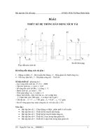
1 Outline
a) Objectives
To shut off influent sewage to wet well in emergency case.
b) Control Configuration
MTU
RTU
COS
MANUAL
AUTO
OPEN
CS
STOP
CLOSE
OPEN
OPEN
BS
STOP
x1
COS
MANUAL
AUTO
COS
LOCAL
LOCAL
OFF
LOCAL = the penstock actuator
MTU
REMOTE
CS
STOP
CLOSE
CLOSE
x1
x1
2 Operation Mode
a) MTU-AUTO
COS position: "AUTO" at MTU, "MTU" at RTU and "REMOTE" at LOCAL
The equipment is controlled by the control logic programmed into the PLC as P01-006.
b) MTU-MANUAL
COS position: "MANUAL" at MTU, "MTU" at RTU and "REMOTE" at LOCAL
The equipment is controlled by an operator on screen at MTU.
3 RTU, MTU and SCADA display
a) Mode: MTU-AUTO / MTU-MANUAL / RTU-AUTO / RTU-MANUAL / LOCAL / OOS
b) Status: OPENED / CLOSED / OPEN / CLOSE / STOP / FAIL
4 Alarm and Status
a) Failed alarm
5 Interlock
c) RTU-AUTO
(None)
COS position: "AUTO" at RTU and "REMOTE" at LOCAL
The equipment is controlled by the control logic programmed into the PLC as P01-006.
d) RTU-MANUAL
COS position: "MANUAL" at RTU and "REMOTE" at LOCAL
The equipment is controlled by an operator on screen at RTU.
6 Special Conditions
a) PLC power up:
To set to RTU-MANUAL mode
b) Power failure:
If power failure, it should be stopped.
If power restore, it should be resumed with the control mode established prior to the power failure.
e) LOCAL
COS position: "LOCAL" at LOCAL
The equipment is controlled by an operator on the actuator.
COS position: "OFF" at LOCAL
Out of service (OOS)
Sheet type: PN
Project
Equipment
Item No.
HUS
Lift Pump
P
01
PU
System / Facility
Quantity
Inst. No.
001-003
Pump System / Pump Station No.1
3
=
2 Duty +
P
01
PSH
001-003
1 Standby
Sheet
Rev.
P01-003
D
1 Outline
a) Objectives
To transfer influent sewage from Catchment Pump Station to Main Pump Station.
b) Control Configuration
MTU
RTU
MCC
COS
MANUAL
AUTO
CS
START
STOP
x3
COS
MANUAL
MANUAL
LOCAL
LOCAL
AUTO
COS
OFF
COS
OFF
CS
MTU
START
BS
RTU
START
STOP
BS
REMOTE
START
STOP
STOP
BS
RESET
BS
E-STOP
x3
1
1st DUTY
2
3
1
2nd DUTY
2
3
x1
x3
x3
LOCAL = LCS
2 Operation Mode
a) MTU-AUTO
COS position: "AUTO" at MTU, "MTU" at RTU, "RTU" at MCC and "REMOTE" at LOCAL
The equipment is controlled by the control logic programmed into the PLC as P01-005.
b) MTU-MANUAL
COS position: "MANUAL" at MTU, "MTU" at RTU, "RTU" at MCC and "REMOTE" at LOCAL
The equipment is controlled by an operator on screen at MTU.
RTU-AUTO
3 RTU, MTU and SCADA display
a) Mode: MTU-AUTO / MTU-MANUAL / RTU-AUTO / RTU-MANUAL / MCC / LOCAL / OOS
b) Status: RUN / STOP / FAIL
4 Alarm and Status
a) Failed alarm
b) Discharge high pressure alarm
5 Interlock
COS position: "AUTO" at RTU, "RTU" at MCC and "REMOTE" at LOCAL
The equipment is controlled by the control logic programmed into the PLC as P01-005.
RTU-MANUAL
COS position: "MANUAL" at RTU, "RTU" at MCC and "REMOTE" at LOCAL
The equipment is controlled by an operator on screen at RTU.
c) MCC
COS position: "MANUAL" at MCC and "REMOTE" at LOCAL
The equipment is controlled by an operator at MCC.
The equipment shall stop on high discharge pressure in any case.
6 Special Conditions
a) PLC power up:
To set to RTU-MANUAL mode
b) Power failure:
If power failure, it should be stopped.
If power restore, it should be resumed with the control mode established prior to the power failure.
COS position: "OFF" at MCC
Out of service (OOS)
A "RESET" push button will clear all equipment faults on MCC panel.
d) LOCAL
COS position: "LOCAL" at LOCAL
The equipment is controlled by an operator at LCS.
COS position: "OFF" at LOCAL
Out of service (OOS)
Sheet type: PU
Project
Equipment
Item No.
HUS
PS No.1 Pump System Logic
P
01
PN
P
01
PU
System / Facility
Quantity
Inst. No.
002
001-003
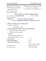
1 Control Configuration
CS
E-STOP
MTU
CS
RESET
RTU
x1
CS
E-STOP
CS
RESET
Instrument: 1) Wet Well Level Instruments (P01LIT001) if PLC is available : Not failed
2) Wet Well Level Instruments (P01LIT002) if PLC or P01LIT001 is not available : Not failed
3) Lift Pump Discharge Pressure Instruments (P01PSH001-003) : Not failed and Not detect H
< Main Control by LIT001 >
START
3)
RTU, MTU and SCADA display
a) Status: RUN / ESTABLISHED
b) Timer setting
4)
Alarm and Status
PLC failed alarm
5)
Interlock
x1
2 Automatic Conditions
Mode: 1) Inlet Penstock : AUTO
2) Lift Pump : AUTO
Pump System / Pump Station No.1
1 set
P
01
LIT
P
01
LIT
P
01
PSH
P01-005
D
Sheet
Rev.
001
002
001-003
a) The equipment shall stop on high discharge pressure
< Wet Well >
< Back-up Control by LIT002 >
: All Automatic Conditions have been established.
HH: Alarm
: All Automatic Conditions have been established.
START
H2: Odor Control STOP
Wet Well Level
Higher than
M2
Wet Well Level
Higher than
M1
T1
T3
Wet Well Level
Lower than
L
M1: 1st Duty Pump START and
2nd Duty Pump STOP
L: 1st Duty Pump STOP
T2
2nd Duty Pump
START
Wet Well Level
Lower than
M1
1st Duty Pump
START
Wet Well Level
At PS08
Higher than
H
Wet Well Level
Lower than
L
2nd Duty Pump
STOP
1st Duty Lift Pump
STOP
Wet Well Level
Higher than
M2
Wet Well Level
Higher than
M1
T1
1st Duty Pump
START
H: Inlet Penstock CLOSE
Odor Control RESTART
M2: 2nd Duty Pump START
T3
T2
LL: Alarm
P1
2nd Duty Pump
START
Wet Well Level
Lower than
M1
Wet Well Level
At PS08
Higher than
H
2nd Duty Pump
STOP
p3
p2
CONTROL BLOCK SELECT 2nd
DUTY PUMP BY TIMER
P1 DUTY
Timer list
No.
T1
T2
T3
Unit
sec
sec
sec
P2 DUTY
Set
15
15
60
Range
0-999
0-999
0-999
1st Duty Lift Pump
STOP
Note: If PLC or P01LIT001 is failed, back-up control should be enabled automatically.
If one duty pump is failed, standby pump should be operate automatically.
If all pump is failed, Inlet Penstock should be close automatically.
If any other failure is occurred during auto sequence running, process for corresponding pump should be stopped.
If wet well water level is higher than H and Inlet Penstock is closed,Inlet Penstock should be opened again by manual operation with appropriate judgement for influent situation.
The pump and associated equipment motors shall stop automatically if there is a power failure at CPS causing a shut-down of the pump works and alarm annunciates.
If wet well water level at PS8 higher than H1 all pump shall stop and restart on water level at Pumping Station 08 below M2
Back-up control logic shall be prepared by hard wiring, not PLC
Sheet type: LG
Project
Equipment
Item No.
HUS
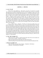
PS No.1 Inlet Penstock System Logic
P
01
PN
System / Facility
Quantity
Inst. No.
002
1 Control Configuration
MTU
CS
E-STOP
CS
RESET
RTU
x1
CS
E-STOP
CS
RESET
Instrument: 1) Wet Well Level Instruments (P01LIT001) if PLC is available : Not failed
2) Wet Well Level Instruments (P01LIT002) if PLC or P01LIT001 is not available : Not failed
< Main Control by LIT001 >
START
3)
RTU, MTU and SCADA display
a) Status: RUN / ESTABLISHED
b) Timer setting
4)
Alarm and Status
PLC failed alarm
5)
Interlock
x1
2 Automatic Conditions
Mode: 1) Inlet Penstock : AUTO
2) Lift Pump : AUTO
Pump System / Pump Station No.1
1 set
P
01
LIT
P
01
LIT
001
002
< Wet Well >
< Back-up Control by LIT002 >
: All Automatic Conditions have been established.
START
P01-006
D
Sheet
Rev.
HH: Alarm
: All Automatic Conditions have been established.
H2: Odor Control STOP
Wet Well Level
Higher than
H
All Lift Pump
Fault
Wet Well Level
Higher than
H
H: Inlet Penstock CLOSE
Odor Control RESTART
M2: 2nd Duty Pump START
All Lift Pump
Fault
M1: 1st Duty Pump START and
2nd Duty Pump STOP
L: 1st Duty Pump STOP
T1
T1
LL: Alarm
Penstock CLOSE
Penstock CLOSE
Penstock Open By Operator
Penstock Open By Operator
Timer list
No.
T1
Unit
sec
Set
15
Range
0-999
Penstock OPEN
Penstock OPEN
Note: If PLC or P01LIT001 is failed, back-up control should be enabled automatically.
If all pump is failed, Inlet Penstock should be close automatically.
If any other failure is occurred during auto sequence running, process for corresponding pump should be stopped.
If wet well water level is higher than H and Inlet Penstock is closed, Inlet Penstock should be opened again by manual operation with appropriate judgement for influent situation.
The pump and associated equipment motors shall stop automatically if there is a power failure at CPS causing a shut-down of the pump works and alarm annunciates.
Back-up control logic shall be prepared by hard wiring, not PLC
Sheet type: LG
Project
Equipment
Item No.
HUS
Basket Screen
P
01
SC
System / Facility
Quantity
Inst. No.
001-003
Pump System / Pump Station No.1
3
=
2 Duty +
P
01
LDIT
010 - 030
1 Standby
Sheet
Rev.
P01-101
D
1 Outline
a) Objectives
To remove solids from raw sewage to prevent fouling and blockage problems within the downstream process equipment.
b) Control Configuration
LOCAL
UP
BS
STOP
DOWN
x3
LOCAL = LCS
2 Operation Mode
a) REMOTE-AUTO
(None)
3 RTU, MTU and SCADA display
a) Mode: (None)
b) Status: Cleaning (or other by supplier)
b) REMOTE-MANUAL
(None)
4 Alarm and Status
a) Failed alarm
b) Differential Level H
c) LOCAL
5 Interlock
The equipment is controlled by an operator at LCS only.
(None)
6 Special Conditions
(None)
Note: The basket screen No.1 and 3 shall be duty and the basket screen No.2 shall be standby.
In case of duty screen failure, the standby basket screen shall be manually put in operation to replace the failed one by opening and closing the associated manual penstocks.
Cleaning process for basket screen shall be implemented manually.
The pump and associated equipment motors shall stop automatically if there is a power failure at CPS causing a shut-down of the pump works and alarm annunciates.
Sheet type: SC
Project
Equipment
Item No.
HUS
Odor Control System
P
01
FN
System / Facility
Quantity
Inst. No.
001
Pump System / Pump Station No.1
1
=
1 Duty +
0 Standby
Sheet
Rev.
P01-201
D
1 Outline
a) Objectives
To collect odor from Pump Station No.1 area and to treat by Granular Activated Carbon Filter (GAC).
b) Control Configuration
RTU
COS
MANUAL
COS
LOCAL
OFF
LOCAL = LCP (by Vendor)
AUTO
LOCAL
REMOTE
CS
START
STOP
BS
START
STOP
x2
2 Operation Mode
a) REMOTE-AUTO
COS position: "REMOTE" at LOCAL and "AUTO" at RTU
The equipment is controlled by the control logic programmed into the PLC as P01-005.
3 RTU, MTU and SCADA display
a) Mode: REMOTE AUTO / REMOTE MANUAL / LOCAL / OSS
b) Status for Fun: RUN / STOP / FAIL
c) (if any by Vendor)
b) REMOTE-MANUAL
COS position : "REMOTE at LOCAL and "MANUAL" at RTU
The equipment is controlled by an operator on screen at RTU.
c) LOCAL
COS position: "AUTO" at LOCAL
The equipment is controlled by own PLC. (by Vendor)
4 Alarm and Status
a) Fun Failed alarm
b) Carbon bed temperature High
c) (if any by Vendor)
COS position: "MANUAL" at LOCAL
The equipment is controlled by an operator at LCP.
5 Interlock
COS position: "OFF" at LOCAL
Out of service (OOS)
a) In the event of an excess temperature raise, power to the blower shall be cut-off.
b) If wet well water level is higher than H2, Odor Control Fan should be stopped.
After the water level down to below H1, the Fan is restarted automatically.
c) (if any by Vendor)
6 Special Conditions
(if any by Vendor)
Note: This system shall be of 24 hrs continuous operation.
This sheet should be reviewed with reference to vendor information.
The pump and associated equipment motors shall stop automatically if there is a power failure at CPS causing a shut-down of the pump works and alarm annunciates.
If wet well water level is raised more than odor intake level, odor control system should be stopped.
Sheet type: GW
Project
Equipment
Item No.
HUS
Electric Jib Hoist
P
01
CR
001
System / Facility
Quantity
Inst. No.
Pump System / Pump Station No.1
1 =
1 Duty +
0 Standby
Sheet
Rev.
P01-301
D
1 Outline
a) Objectives
To lift and transfer the Lift Pumps or others for maintenance.
b) Control Configuration
BS
UP
DOWN x 1
LOCAL = Control device as equipment accessories (by Vendor)
Only power feed
LOCAL
2 Operation Mode
a) REMOTE-AUTO
(None)
3 RTU, MTU and SCADA display
(None)
b) REMOTE-MANUAL
(None)
4 Alarm and Status
(None)
c) LOCAL
5 Interlock
The equipment is controlled by an operator at site.
(None)
6 Special Conditions
(None)
Sheet type: MC
Project
Equipment
Item No.
HUS
Overflow Chamber and Wet Well
System / Facility
Quantity
Inst. No.
Pump System / Pump Station No.2
1
=
1 Duty +
P
02
FIT
001
P
02
LSH
001
P
02
LIT
001
P
02
LIT
002
0 Standby
Sheet
Rev.
P02-001
D
( for main control)
(for buck-up control)
1 Outline
a) Objectives
To receive sewage from catchment system, then send to Main Pump Station.
b) Control Configuration
(None)
2 Operation Mode
a) REMOTE-AUTO
(None)
b) REMOTE-MANUAL
(None)
c) LOCAL
(None)
3 MTU and SCADA display
a) Inlet Flow (xx.xx m3/h)
b) Wet Well Level (xx.xx m , %)
4 Alarm and Status
a) Flow instrument Failed alarm
b) Level instrument Failed alarm
c) Overflow Chamber Level H
d) Wet Well Level HH
e) Wet Well Level LL
f) Building services and fire alarm (if required)
5 Interlock
(None)
6 Special Conditions
(None)
Sheet type: TK
Project
Equipment
Item No.
HUS
Inlet Penstock-Pump Station Inlet
P
02
PN
System / Facility
Quantity
Inst. No.
002
Pump System / Pump Station No.2
1
=
1 Duty +
0 Standby
Sheet
Rev.
P02-002
D
1 Outline
a) Objectives
To shut off influent sewage to wet well in emergency case.
b) Control Configuration
MTU
RTU
COS
MANUAL
AUTO
OPEN
CS
STOP
CLOSE
OPEN
OPEN
BS
STOP
x1
COS
MANUAL
AUTO
COS
LOCAL
LOCAL
OFF
LOCAL = the penstock actuator
MTU
REMOTE
CS
STOP
CLOSE
CLOSE
x1
x1
2 Operation Mode
a) MTU-AUTO
COS position: "AUTO" at MTU, "MTU" at RTU and "REMOTE" at LOCAL
The equipment is controlled by the control logic programmed into the PLC as P02-06.
b) MTU-MANUAL
COS position: "MANUAL" at MTU, "MTU" at RTU and "REMOTE" at LOCAL
The equipment is controlled by an operator on screen at MTU.
3 RTU, MTU and SCADA display
a) Mode: MTU-AUTO / MTU-MANUAL / RTU-AUTO / RTU-MANUAL / OOS
b) Status: OPENED / CLOSED / OPEN / CLOSE / STOP / FAIL
4 Alarm and Status
a) Failed alarm
5 Interlock
(None)
c) RTU-AUTO
COS position: "AUTO" at RTU and "REMOTE" at LOCAL
The equipment is controlled by the control logic programmed into the PLC as P02-005.
d) RTU-MANUAL
COS position: "MANUAL" at RTU and "REMOTE" at LOCAL
The equipment is controlled by an operator on screen at RTU.
6 Special Conditions
a) PLC power up:
To set to RTU-MANUAL mode
b) Power failure:
If power failure, it should be stopped.
If power restore, it should be resumed with the control mode established prior to the power failure.
e) LOCAL
COS position: "LOCAL" at LOCAL
The equipment is controlled by an operator on the actuator.
COS position: "OFF" at LOCAL
Out of service (OOS)
Sheet type: PN
Project
Equipment
Item No.
HUS
Lift Pump
P
02
PU
System / Facility
Quantity
Inst. No.
001-003
Pump System / Pump Station No.2
3
=
2 Duty +
P
02
PSH
001-003
1 Standby
Sheet
Rev.
P02-003
D
1 Outline
a) Objectives
To transfer influent sewage from Catchment Pump Station to Main Pump Station.
b) Control Configuration
MTU
RTU
MCC
COS
MANUAL
AUTO
CS
START
STOP
x3
COS
MANUAL
MANUAL
LOCAL
LOCAL
AUTO
COS
OFF
COS
OFF
CS
MTU
START
BS
RTU
START
STOP
BS
REMOTE
START
STOP
STOP
BS
RESET
BS
E-STOP
x3
1
1st DUTY
2
3
1
2nd DUTY
2
3
x1
x3
x3
LOCAL = LCS
2 Operation Mode
a) MTU-AUTO
COS position: "AUTO" at MTU, "MTU" at RTU, "RTU" at MCC and "REMOTE" at LOCAL
The equipment is controlled by the control logic programmed into the PLC as P02-005.
b) MTU-MANUAL
COS position: "MANUAL" at MTU, "MTU" at RTU, "RTU" at MCC and "REMOTE" at LOCAL
The equipment is controlled by an operator on screen at MTU.
RTU-AUTO
3 RTU, MTU and SCADA display
a) Mode: MTU-AUTO / MTU-MANUAL / RTU-AUTO / RTU-MANUAL / MCC / LOCAL / OOS
b) Status: RUN / STOP / FAIL
4 Alarm and Status
a) Failed alarm
b) Discharge high pressure alarm
5 Interlock
COS position: "AUTO" at RTU, "RTU" at MCC and "REMOTE" at LOCAL
The equipment is controlled by the control logic programmed into the PLC as P02-005.
RTU-MANUAL
COS position: "MANUAL" at RTU, "RTU" at MCC and "REMOTE" at LOCAL
The equipment is controlled by an operator on screen at RTU.
c) MCC
COS position: "MANUAL" at MCC and "REMOTE" at LOCAL
The equipment is controlled by an operator at MCC.
The equipment shall stop on high discharge pressure in any case.
6 Special Conditions
a) PLC power up:
To set to RTU-MANUAL mode
b) Power failure:
If power failure, it should be stopped.
If power restore, it should be resumed with the control mode established prior to the power failure.
COS position: "OFF" at MCC
Out of service (OOS)
A "RESET" push button will clear all equipment faults on MCC panel.
d) LOCAL
COS position: "LOCAL" at LOCAL
The equipment is controlled by an operator at LCS.
COS position: "OFF" at LOCAL
Out of service (OOS)
Sheet type: PU
Project
Equipment
Item No.
HUS
PS No.2 Pump System Logic
P
02
PN
P
02
PU
System / Facility
Quantity
Inst. No.
002
001-003
1 Control Configuration
MTU
CS
E-STOP
CS
RESET
RTU
x1
CS
E-STOP
CS
RESET
Pump System / Pump Station No.2
1 set
P
02
LIT
P
02
LIT
P
02
PSH
P02-005
D
Sheet
Rev.
001
002
001-003
3 RTU, MTU and SCADA display
a) Status: RUN / ESTABLISHED
b) Timer setting
x1
2 Automatic Conditions
Mode: 1) Inlet Penstock : AUTO
2) Lift Pump : AUTO
4 Alarm and Status
PLC failed alarm
Instrument: 1) Wet Well Level Instruments (P02LIT001) if PLC is available : Not failed
2) Wet Well Level Instruments (P02LIT002) if PLC or P02LIT001 is not available : Not failed
3) Lift Pump Discharge Pressure Instruments (P02PSH001-003) : Not failed and Not detect H
< Main Control by LIT001 >
5 Interlock
a) The equipment shall stop on high discharge pressure
< Back-up Control by LIT002 >
< Wet Well >
START
START
: All Automatic Conditions have been established.
HH: Alarm
: All Automatic Conditions have been established.
H2: Odor Control STOP
Wet Well Level
Higher than
M2
Wet Well Level
Higher than
M1
T1
T3
T2
T1
H1: Inlet Penstock CLOSE
Odor Control RESTART
M2: 2nd Duty Pump START
Wet Well Level
Higher than
M2
Wet Well Level
Higher than
M1
T3
M1: 1st Duty Pump START and
2nd Duty Pump STOP
L: 1st Duty Pump STOP
T2
LL: Alarm
1st Duty Pump
START
Wet Well Level
Lower than
L
2nd Duty Pump
START
Wet Well Level
Lower than
M1
1st Duty Pump
START
Wet Well Level
At PS08
Higher than
H
Wet Well Level
Lower than
L
2nd Duty Pump
STOP
1st Duty Lift Pump
STOP
Wet Well Level
Lower than
M1
p2
P1
2nd Duty Pump
START
Wet Well Level
At PS08
Higher than
H
2nd Duty Pump
STOP
1st Duty Lift Pump
STOP
p3
CONTROL BLOCK SELECT 2nd
DUTY PUMP BY TIMER
P1 DUTY
P2 DUTY
Timer list
No.
T1
T2
T3
Unit
sec
sec
sec
Set
15
15
60
Range
0-999
0-999
0-999
Note: If PLC or P02LIT001 is failed, back-up control should be enabled automatically.
If one duty pump is failed, standby pump should be operate automatically.
If all pump is failed, Inlet Penstock should be close automatically.
If any other failure is occurred during auto sequence running, process for corresponding pump should be stopped.
If wet well water level is higher than H and Inlet Penstock is closed,Inlet Penstock should be opened again by manual operation with appropriate judgement for influent situation.
The pump and associated equipment motors shall stop automatically if there is a power failure at CPS causing a shut-down of the pump works and alarm annunciates.
If wet well water level at PS8 higher than H1 all pump shall stop and restart on water level at Pumping Station 08 below M2
Back-up control logic shall be prepared by hard wiring, not PLC
Sheet type: LG
Project
Equipment
Item No.
HUS
PS No.1 Penstock System Logic
P
02
PN
System / Facility
Quantity
Inst. No.
002
1 Control Configuration
MTU
CS
E-STOP
CS
RESET
x1
RTU
CS
E-STOP
CS
RESET
Instrument: 1) Wet Well Level Instruments (P02LIT001) if PLC is available : Not failed
2) Wet Well Level Instruments (P02LIT002) if PLC or P01LIT001 is not available : Not failed
< Main Control by LIT001 >
START
3)
RTU, MTU and SCADA display
a) Status: RUN / ESTABLISHED
b) Timer setting
4)
Alarm and Status
PLC failed alarm
5)
Interlock
x1
2 Automatic Conditions
Mode: 1) Inlet Penstock : AUTO
2) Lift Pump : AUTO
Pump System / Pump Station No.2
1 set
P
02
LIT
P
2
LIT
001
002
< Wet Well >
< Back-up Control by LIT002 >
: All Automatic Conditions have been established.
START
P02-006
D
Sheet
Rev.
HH: Alarm
: All Automatic Conditions have been established.
H2: Odor Control STOP
Wet Well Level
Higher than
H
All Lift Pump
Fault
Wet Well Level
Higher than
H
H: Inlet Penstock CLOSE
Odor Control RESTART
M2: 2nd Duty Pump START
All Lift Pump
Fault
M1: 1st Duty Pump START and
2nd Duty Pump STOP
L: 1st Duty Pump STOP
T1
T1
LL: Alarm
Penstock CLOSE
Penstock CLOSE
Open By Operator
Open By Operator
Timer list
No.
T1
Unit
sec
Set
15
Range
0-999
Penstock OPEN
Penstock OPEN
Note: If PLC or P02LIT001 is failed, back-up control should be enabled automatically.
If all pump is failed, Inlet Penstock should be close automatically.
If any other failure is occurred during auto sequence running, process for corresponding pump should be stopped.
If wet well water level is higher than H and Inlet Penstock is closed, Inlet Penstock should be opened again by manual operation with appropriate judgement for influent situation.
The pump and associated equipment motors shall stop automatically if there is a power failure at CPS causing a shut-down of the pump works and alarm annunciates.
Back-up control logic shall be prepared by hard wiring, not PLC
Sheet type: LG
Project
Equipment
Item No.
HUS
Mechanical Bar Screen
P
02
SC
System / Facility
Quantity
Inst. No.
001-003
Pump System / Pump Station No.2
3
=
2 Duty + 1 Standby
P
02
LDIT
010 - 030
Sheet
Rev.
P02-101
D
1 Outline
a) Objectives
To remove solids from raw sewage to prevent fouling and blockage problems within the downstream process equipment.
b) Control Configuration
COS
MANUAL
AUTO
COS
RTU
MANUAL
AUTO
COS
LOCAL
LOCAL
OFF
LOCAL = LCP (by Vendor)
MTU
CS
STOP
REVERSE x 3
CS
FORWARD
MTU
STOP
REVERSE x 3
CS
BS
REMOTE FORWARD
STOP
REVERSE E-STOP
FORWARD
x3
2 Operation Mode
a) REMOTE-AUTO
COS position: "AUTO" at MTU and "REMOTE" at LOCAL
The equipment is controlled by the control logic programmed into the PLC as P02-103.
b) REMOTE-MANUAL
COS position: "MANUAL" at MTU and "REMOTE" at LOCAL
The equipment is controlled by an operator on SCADA screen.
3 MTU and SCADA display
a) Mode: REMOTE-AUTO / REMOTE-MANUAL / OOS
b) Status: FORWARD / STOP / REVERSE / FAIL
4 Alarm and Status
a) Failed alarm
b) Differential Level H
c) Mechanical over load
5 Interlock
c) LOCAL
a) Except for LOCAL mode, the equipment shall not operate if associated Inlet Penstock is closed.
COS position: "LOCAL" at LOCAL
The equipment is controlled by an operator at LCS.
COS position: "OFF" at LOCAL
Out of service (OOS)
6 Special Conditions
a) PLC power up:
To set to REMOTE-MANUAL mode
b) Power failure:
If power failure, it should be stopped.
If power restore, it should be resumed with the control mode established prior to the power failure.
Note: In case of duty screen failure, the standby bar screen shall be manually put in operation to replace the failed one by opening and closing the associated manual penstocks.
Sheet type: SC
Project
Equipment
Item No.
HUS
Screen Conveyor
P
02
CS
System / Facility
Quantity
Inst. No.
001
Pump System / Pump Station No.2
1
=
1 Duty +
0 Standby
Sheet
Rev.
P02-102
D
1 Outline
a) Objectives
To convey and dewater screenings for disposal.
b) Control Configuration
COS
MANUAL
AUTO
COS
RTU
MANUAL
AUTO
COS
LOCAL
LOCAL
OFF
LOCAL = LCP (by Vendor)
MTU
CS
STOP
REVERSE x 3
CS
FORWARD
MTU
STOP
REVERSE x 3
CS
BS
REMOTE FORWARD
STOP
REVERSE E-STOP
FORWARD
x3
REVERSE NOT HOLD
2 Operation Mode
a) REMOTE-AUTO
COS position: "AUTO" at MTU and "REMOTE" at LOCAL
The equipment is controlled by the control logic programmed into the PLC as P02-103.
b) REMOTE-MANUAL
COS position: "MANUAL" at MTU and "REMOTE" at LOCAL
The equipment is controlled by an operator on SCADA screen.
3 MTU and SCADA display
a) Mode: REMOTE-AUTO / REMOTE-MANUAL / LOCAL / OOS
b) Status: FORWARD / STOP / REVERSE / FAIL
4 Alarm and Status
a) Failed alarm
5 Interlock
(None)
c) LOCAL
COS position: "LOCAL" at LOCAL
The equipment is controlled by an operator at LCS.
COS position: "OFF" at LOCAL
Out of service (OOS)
6 Special Conditions
a) PLC power up:
To set to REMOTE-MANUAL mode
b) Power failure:
If power failure, it should be stopped.
If power restore, it should be resumed with the control mode established prior to the power failure.
Sheet type: SC
Project
Equipment
Item No.
HUS
PS No.2 Screen System Logic
P
02
SC
P
02
CS
System / Facility
Quantity
Inst. No.
001-003
001
1 Control Configuration
MTU
CS
E-STOP
CS
RESET
Pump System / Pump Station No.2
1 set
P
02
LDIT
Sheet
Rev.
010 - 030
2 Automatic Conditions
Mode: 1) Mechanical Bar Screen : Auto
2) Screen Conveyor : Auto
x1
P02-103
D
Instrument: 1) Level Ultrasonic System (P02LDIT010-030) for AUTO selected Mechanical Bar Screen : Not failed
3 SCADA display
a) Status: RUN / ESTABLISHED
b) Timer setting
c) Differential level setting (xx.xx m)
STOP
START
<<Interrupt sequence>>
(This sequence applies when Clock timer sequence is not run.)
: All Automatic Conditions have been established.
START
: All Automatic Conditions have been established.
Clock timer
On
Differential level "X"
H
Screen Conveyor
Start
Screen Conveyor
Start
Mechanical Bar Screen "2nd Duty"
Start
MBS1
T1
Mechanical Bar Screen "1st Duty"
Start
T2
MBS2
MBS3
CONTROL BLOCK SELECT DUTY
MECHANICAL BAR SCREEN
BY OPERATOR
T1
Mechanical Bar Screen "X"
Start
T2
Mechanical Bar Screen "2nd Duty"
Stop
1st Duty
2nd Duty
STOP
Differential level "X"
L
Mechanical Bar Screen "1st Duty"
Stop
T5
or
T4
Mechanical Bar Screen "X"
Stop
Alarm Diferential level "X"
T3
T4
Screenings Conveyor
Stop
Screen Conveyor
Stop
Note: "A" and "X" shows any available fine screen number.
If any failure is occurred during auto sequence running, the sequence should be stopped.
The pump motor shall stop automatically if there is a power failure at MPS causing a shut-down of the pumping works and alarm annunciates.
Timer list
No.
Unit
Clock timer xx hr/yy min
T1
sec
T2
min
T3
sec
T4
sec
T5
min
Set
Range
TBD
24 hrs
10
10
10
10
10
0-999
0-999
0-999
0-999
0-999
Sheet type: LG
Project
Equipment
Item No.
HUS
Odor Control System
P
02
P
02
AC
FN
System / Facility
Quantity
Inst. No.
001
001
Pump System / Pump Station No.2
1
=
1
P
02
DPI
P
02
FI
P
02
TIT
Duty +
xx-xx
xx-xx
xx-xx
0 Standby
Sheet
Rev.
P02-201
D
1 Outline
a) Objectives
To collect odor from Pump Station No.8 area and to treat by Granular Activated Carbon Filter (GAC).
b) Control Configuration
RTU
COS
MANUAL
COS
LOCAL
OFF
LOCAL = LCP (by Vendor)
LOCAL
AUTO
START
CS
STOP
BS
REMOTE
START
STOP
x2
2 Operation Mode
a) REMOTE AUTO
COS position : "AUTO" at RTU and "REMOTE" at LOCAL
The equipment is controlled by the control logic programmed into the PLC as P01-005.
3 MTU and SCADA display
a) Mode: REMOTE AUTO / REMOTE MANUAL / LOCAL / OOS
b) Status for Fun: RUN / STOP / FAIL
c) (if any by Vendor)
b) REMOTE MANUAL
COS position : "MANUAL" at RTU and "REMOTE" at LOCAL
The equipment is controlled by an operator on screen at RTU.
c) LOCAL
COS position: "AUTO" at LOCAL
The equipment is controlled by own PLC. (by Vendor)
4 Alarm and Status
a) Fun Failed alarm
b) Carbon bed temperature High
c) (if any by Vendor)
COS position: "MANUAL" at LOCAL
The equipment is controlled by an operator at LCP.
5 Interlock
COS position: "OFF" at LOCAL
Out of service (OOS)
a) In the event of an excess temperature raise, power to the blower shall be cut-off.
b) If wet well water level is higher than H2, Odor Control Fan should be stopped
c) After the water level down to below H1, the Fan is restarted automatically
d) (if any by Vendor)
6 Special Conditions
(if any by Vendor)
Note: This system shall be of 24 hrs continuous operation.
This sheet should be reviewed with reference to vendor information.
The pump motor shall stop automatically if there is a power failure at MPS causing a shut-down of the pumping works and alarm annunciates.
If wet well water level is raised more than odor intake level, odor control system should be stopped.
Sheet type: GW
Project
Equipment
Item No.
HUS
Electric Jib Hoist
P
02
CR
001
System / Facility
Quantity
Inst. No.
Pump System / Pump Station No.2
1 =
1 Duty +
0 Standby
Sheet
Rev.
P02-301
D
1 Outline
a) Objectives
To lift and transfer the Lift Pumps or others for maintenance.
b) Control Configuration
BS
UP
DOWN x 1
LOCAL = Control device as equipment accessories (by Vendor)
Only power feed
LOCAL
2 Operation Mode
a) REMOTE-AUTO
(None)
3 MTU and SCADA display
(None)
b) REMOTE-MANUAL
(None)
4 Alarm and Status
(None)
c) LOCAL
5 Interlock
The equipment is controlled by an operator at site.
(None)
6 Special Conditions
(None)
Sheet type: MC
Project
Equipment
Item No.
HUS
Overflow Chamber and Wet Well
System / Facility
Quantity
Inst. No.
Pump System / Pump Station No.4
1
=
1 Duty +
P
04
FIT
001
P
04
LSH
001
P
04
LIT
001
P
04
LIT
002
0 Standby
Sheet
Rev.
P04-001
D
( for main control)
(for buck-up control)
1 Outline
a) Objectives
To receive sewage from catchment system, then send to Main Pump Station.
b) Control Configuration
(None)
2 Operation Mode
a) REMOTE-AUTO
(None)
b) REMOTE-MANUAL
(None)
c) LOCAL
(None)
3 MTU and SCADA display
a) Inlet Flow (xx.xx m3/h)
b) Wet Well Level (xx.xx m , %)
4 Alarm and Status
a) Flow instrument Failed alarm
b) Level instrument Failed alarm
c) Overflow Chamber Level H
d) Wet Well Level HH
e) Wet Well Level LL
f) Building services and fire alarm (if required)
5 Interlock
(None)
6 Special Conditions
(None)
Sheet type: TK
Project
Equipment
Item No.
HUS
Inlet Penstock-Pump Station Inlet
P
04
PN
System / Facility
Quantity
Inst. No.
002
Pump System / Pump Station No.4
1
=
1 Duty +
0 Standby
Sheet
Rev.
P04-002
D
1 Outline
a) Objectives
To shut off influent sewage to wet well in emergency case.
b) Control Configuration
MTU
RTU
COS
MANUAL
AUTO
OPEN
CS
STOP
CLOSE
OPEN
OPEN
BS
STOP
x1
COS
MANUAL
AUTO
COS
LOCAL
LOCAL
OFF
LOCAL = the penstock actuator
MTU
REMOTE
CS
STOP
CLOSE
CLOSE
x1
x1
2 Operation Mode
a) MTU-AUTO
COS position: "AUTO" at MTU, "MTU" at RTU and "REMOTE" at LOCAL
The equipment is controlled by the control logic programmed into the PLC as P04-005.
b) MTU-MANUAL
COS position: "MANUAL" at MTU, "MTU" at RTU and "REMOTE" at LOCAL
The equipment is controlled by an operator on screen at MTU.
3 RTU, MTU and SCADA display
a) Mode: MTU-AUTO / MTU-MANUAL / RTU-AUTO / RTU-MANUAL / LOCAL / OOS
b) Status: OPENED / CLOSED / OPEN / CLOSE / STOP / FAIL
4 Alarm and Status
a) Failed alarm
5 Interlock
c) RTU-AUTO
COS position: "AUTO" at RTU and "REMOTE" at LOCAL
The equipment is controlled by the control logic programmed into the PLC as P04-005.
d) RTU-MANUAL
COS position: "MANUAL" at RTU and "REMOTE" at LOCAL
The equipment is controlled by an operator on screen at RTU.
6 Special Conditions
a) PLC power up:
To set to RTU-MANUAL mode
b) Power failure:
If power failure, it should be stopped.
If power restore, it should be resumed with the control mode established prior to the power failure.
e) LOCAL
COS position: "LOCAL" at LOCAL
The equipment is controlled by an operator on the actuator.
COS position: "OFF" at LOCAL
Out of service (OOS)
Sheet type: PN