Wheel Slip Control for the Electric Vehicle With InWheel Motors
Bạn đang xem bản rút gọn của tài liệu. Xem và tải ngay bản đầy đủ của tài liệu tại đây (2.54 MB, 10 trang )
IEEE TRANSACTIONS ON INDUSTRIAL ELECTRONICS, VOL. 67, NO. 10, OCTOBER 2020
8535
Wheel Slip Control for the Electric Vehicle With
In-Wheel Motors: Variable Structure and
Sliding Mode Methods
Dzmitry Savitski , Member, IEEE, Valentin Ivanov , Senior Member, IEEE, Klaus Augsburg,
Tomoki Emmei , Student Member, IEEE, Hiroyuki Fuse, Hiroshi Fujimoto, Senior Member, IEEE,
and Leonid M. Fridman
Abstract—The article introduces four variants of the controller design for a continuous wheel slip control (WSC)
system developed for the full electric vehicle equipped with
individual in-wheel motors for each wheel. The study includes explanation of the WSC architecture, design of controllers, and their validation on road tests. The investigated
WSC design variants use variable-structure proportionalintegral, first-order sliding mode, integral sliding mode
controllers as well as continuous twisting algorithm. To
compare their functionality, a benchmark procedure is
proposed based on several performance factors responsible for driving safety, driving comfort, and control quality.
The controllers are compared by the results of validation
tests done on low-friction road surface.
Index Terms—Continuous twisting algorithm (CTA), electric vehicle (EV), in-wheel motors (IWMs), sliding mode control, variable structure systems, wheel slip control (WSC).
I. INTRODUCTION
F
ULL electric vehicles (EVs) with individually controlled
electric motors for each wheel are becoming a wide
Manuscript received December 31, 2018; revised July 20, 2019; accepted September 6, 2019. Date of publication November 4, 2019; date
of current version June 3, 2020. This work was supported in part by the
European Union’s Horizon 2020 research and innovation programme
under the Marie Skodowska-Curie Grant 734832, in part by the Ministry
of Education, Culture, Sports, Science and Technology of Japan under
Grant 22246057 and Grant 26249061, in part by the New Energy and
Industrial Technology Development under Grant 05A48701d, Consejo
Nacional de Ciencia y Tecnologia under Grant 282013, and Programa
de Apoyo a Proyectos de Investigacion e Innovacion Tecnologica Grant
IN 115419. (Corresponding author: Valentin Ivanov.)
D. Savitski is with the Arrival Germany GmbH, 75172 Pforzheim,
Germany (e-mail: ).
V. Ivanov and K. Augsburg are with the Automotive Engineering
Group, Technical University of Ilmenau, 98693 Ilmenau, Germany
(e-mail: ; klaus.augsburg@tu-ilmenau.
de).
T. Emmei, H. Fuse, and H. Fujimoto are with the Department of
Advanced Energy, Graduate School of Frontier Sciences, The University
of Tokyo, Kashiwa 277-8561, Japan (e-mail: ; ;
ac.jp).
L. M. Fridman is with the Department of Control and Robotics Engineering, National Autonomous University of Mexico, Mexico 04510,
Mexico (e-mail: ).
Color versions of one or more of the figures in this article are available
online at .
Digital Object Identifier 10.1109/TIE.2019.2942537
distribution in road transportation not only thanks to their
environment-friendliness but also due to their agile and efficient
motion dynamics. This was confirmed by many preliminary
industrial studies, e.g., [1], [2], which have motivated further
developments in EV motion control. Substantial advantages by
designing of EV dynamics control systems can be provided by
in-wheel motors (IWMs) as actuators in comparison with an
internal combustion engine and friction brakes in conventional
vehicles. These advantages are caused by the following factors:
1) IWM technology provides a quicker system response and has
relatively high system bandwidth; 2) the output motor torque can
be accurately measured from current that increase the control
precision; and 3) all wheels can be controlled independently
from each other allowing individual wheel torque control. As
a result, new design principles and control architectures can be
proposed for motion control systems in EVs with IWMs. Recent
state-of-the-art surveys demonstrate that most of studies in this
area are dedicated to torque vectoring, direct yaw control, and
traction control systems [3], [4]. But the wheel slip control in a
braking mode, despite its cardinal importance to any motion
control systems, is still insufficiently addressed in published
studies for the EVs with individually controlled electric motors.
In many cases, the developers rather adopt algorithms taken
from conventional antilock braking systems (ABS) and consider
blended actuation of IWMs and friction brakes [5], [6] than propose WSC methods for a pure regenerative braking. However,
exactly for this EV operational mode, the benefits of IWMs as
actuators can be realized in a full measure. It concerns first of
all the possibility to realize a continuous WSC that is opposite
to a more common rule-based (RB) control approach.
The continuous WSC was initially proposed for decoupled
brake-by-wire systems [7], [8] and demonstrated very precise
tracking of reference wheel slip without pronounced brake
torque oscillations typical of RB ABS. However, this approach
was not deeply investigated during last decade, mainly due to
limited use of brake-by-wire systems on mass-production cars.
But for EVs, the relevant studies are gained a new impetus
because on-board and IWMs allow efficient implementation of
continuous wheel torque control.
The continuous WSC in EV can be realized in practice with
different analytical approaches. Analysis of recent studies allows
identifying three main major approaches in this regard. The
This work is licensed under a Creative Commons Attribution 4.0 License. For more information, see />
8536
IEEE TRANSACTIONS ON INDUSTRIAL ELECTRONICS, VOL. 67, NO. 10, OCTOBER 2020
first group covers solutions based on more traditional nonlinear
control methods as Lyapunov-based and proportional integral
derivative (PID). One of the well-known approaches is based
on so-called maximum transmissible torque estimation (MTTE)
scheme allowing the controller design without the use of information about the vehicle velocity and tire-road friction [9].
The MTTE scheme with the proportional integral (PI) controller
demonstrated good applicability for WSC on small EV with
low operational velocities in a traction mode [10], however,
such a design has been rarely studied for conventional passenger
cars and for the braking mode. Another solution is proposed in
the work [11] investigating the WSC, which uses the barrier
Lyapunov function and is integrated with active suspension
control. This method demonstrated sufficient braking performance but only in the simulation for a quarter car model. In
general, it should be mentioned that only few WSC studies
considered a full-scale validation on the mass-production cars.
One of the recent experimental works in this regard has been
performed for a full electric sport utility vehicle with four
on-board motors, where a pure regenerative ABS were realized
with gain-scheduled PI direct slip control with feed-forward and
feedback control contributions [12]. The outcomes confirmed
that continuous WSC with electric motors as actuators allows
achieving simultaneous effect in high brake performance and
improved driving comfort thanks to vehicle jerk damping.
The basic tool for the second group is model predictive control
(MPC). A variant of a centralized MPC has been proposed in [13]
for blended WSC with motors and friction brakes as redundant
actuators. This variant demonstrated sufficient real-time applicability and good torque tracking in low-slip area. Simulation
studies on nonlinear MPC-based WSC have been published
in [14] (focus on uneven snow surface conditions), [15] (focus on blended ABS design), and [16] (focus on robustness
against noise injection by the road profile). Some limitations
of MPC are known regarding real-time performance; therefore,
the MPC-based WSC on real vehicles is still rarely investigated.
However, recent studies using hardware-in-the-loop technique
confirmed sufficient performance of nonlinear MPC as a tool for
continuous WSC [17].
The third group unites a variety of WSC methods based
on sliding mode techniques. For example, the work [18] used
sliding mode (SM) method for EV traction control with optimal
slip seeking. A similar variant, but for an ABS mode, has been
discussed in [19]. To increase robustness, some studies proposed
integration of SM control technique with other methods. For
instance, Verma et al. [20] introduced SM control combined with
inertial delay control for estimating uncertainties at braking.
Another example is provided by Zhang and Li [21], where a
radial basis function neural network is added to SM WSC for
the predefinition of optimal slip. An analysis of state-of-the-art
solutions for WSC using SM methods allows identifying most
common drawbacks of relevant studies: 1) their validation is
mostly limited by simulation for a limited number of test cases;
2) optimal or reference slip is often selected in very high area λ =
0.1...0.2, even for low-friction surfaces, that does not correspond
to real road conditions; and 3) the controllers demonstrate a
chattering effect, particularly at low velocities.
Despite these drawbacks, the authors selected SM technique
due to its robustness and relatively low computational costs for
further study on WSC for EV with IWMs. It should be noted
that there are also no clear recommendations in the literature
regarding the selection of the most suitable SM strategy for EV
control. In particular, analysis in [22] allows us to conclude that
PI control proposes more effective wheel slip control than classical first-order SM and second-order SM. However, performed
theoretical analysis in [23] indicates that integral sliding mode
(ISM) is the most promising control over other SM controls.
The latest conclusion is also confirmed in [24] and [25], though
for the decoupled electro-hydraulic brake system. Therefore,
the authors decided to design several concurrent variants of the
controller with their benchmark by experimental results. The
selected variants are as follows.
1) Variable structure PI (VSPI) as a method demonstrating
integration of variable structure control techniques with
the continuous PI control method.
2) The first-order SM, known for its issues with the chattering, to investigate IWM potentials as highly dynamic
WSC actuator.
3) Integral SM recommended by other studies as a method
demonstrating high robustness against delays and less
overshooting.
4) SM with continuous twisting algorithm (CTA) characterized by the finite-time convergence of the control signal
to the uncertainties. It should be especially noted that
CTA approach is one of the recent advancements in SM
control and there are no known experimental studies
demonstrating its real-time application to such highly
dynamic systems as EV WSC.
For these controller variants, the following objectives are
formulated for the presented study:
1) to validate functionality of developed WSC variants using
experiments on the proving ground in inhomogeneous and
severe road surface conditions characterized by distinctive uncertainties;
2) to propose methodology for benchmark of different WSC
variants and compare the developed systems using this
methodology.
Next sections introduce how the proposed objectives and targets are achieved. Overall configuration and technical data of the
target EV are given in Section II. Section III gives required introduction in wheel slip dynamics and its control targets. Then, the
proposed continuous wheel slip control methods are explained
in Section IV. The solution for the wheel slip estimation as an
important WSC component is given Section V. The proposed
continuous WSC methods are initially validated and compared
in simulation studies described in Section V and, then, with real
experiments presented in Section VI. Section VII concludes this
article.
II. VEHICLE SPECIFICATION
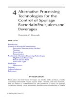
The vehicle used in this article has been built at the University of Tokyo, Fig. 1, and is equipped with four individual
outer-rotor-type IWMs, which adopt a principle of direct drive
SAVITSKI et al.: WSC FOR THE EV WITH IWMs: VARIABLE STRUCTURE AND SLIDING MODE METHODS
8537
Fig. 1. Vehicle demonstrator FPEV2-Kanon with four individual electric
motors.
TABLE I
VEHICLE TECHNICAL DATA
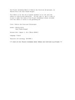
Fig. 2.
Structure of the wheel slip controller.
Neglecting tire transient dynamics, the force Fx can be calculated as nonlinear function of the wheel slip λ
Fx = Fz μroad (λ)
(2)
where μroad is the road coefficient of friction, and Fz is the
vertical tire force.
For the longitudinal vehicle motion and braking mode, the
wheel slip λ is calculated as
λ=
system. It implies that reaction forces from the road are transmitted directly to the motors without gear reduction or backlash.
Technical data of the test vehicle are given in Table I.
During the tests, the vehicle velocity is measured by the
Corevit optical sensor. The dSPACE real-time platform with
ds1003 processor board is installed on the vehicle for all required
on-board control systems.
III. WHEEL SLIP DYNAMICS
The WSC algorithms developed in this study are using a single
corner model, which can be described as follows:
mV˙ x = −Fx
Jw ω˙ w = Fx rw − Tb
ωw rw − Vx
.
Vx
(3)
Considering V > 0 and ωw > 0, the wheel slip dynamics can
be described in general as
1
λ˙ = −
Vx
1
r2
(1 − λ) + w
m
Jw
Fz μroad (λ) +
rw
Tb .
Jw Vx
(4)
The proposed interpretation of the wheel dynamics is sufficient for the design of the wheel slip control that was confirmed
by the corresponding analysis done in [26]. However, it should
be especially mentioned that the effect of the load distribution
at the braking as well as eventual fluctuations of the road
friction during the maneuver are handled as uncertainty in the
controllers, which will be introduced in next section.
IV. WHEEL SLIP CONTROL
(1)
where Vx is the vehicle velocity, m is the mass of quarter vehicle,
Fx is the tire longitudinal force, Jw is the wheel inertia, ωw is
the angular wheel velocity, rw is the wheel radius, and Tb is the
braking torque produced by electric motor.
A. General Controller Structure
In the proposed structure of the wheel slip controller, Fig. 2,
the overall base brake torque Tbb for the vehicle is computed
from the driver demand, which can be defined through the
brake pedal actuation dynamics, e.g., from the brake pedal
displacement sped . The proposed WSC architecture for vehicle
8538
IEEE TRANSACTIONS ON INDUSTRIAL ELECTRONICS, VOL. 67, NO. 10, OCTOBER 2020
with IWMs uses principle of direct slip control and generates
∗
necessary for maintaining
electric motor torque demand Tem
∗
desired wheel slip λ . The WSC is being activated individually
for each wheel when wheel slip λ is higher than reference λ∗ .
Deactivation happens if torque demand from distribution function is lower than the torque from WSC. Under this conditions,
WSC or distributed torque demand are bypassed to the low-level
electric motor controller. In this article, the reference wheel slip
value is fixed at the value close to the optimum.
The structure includes also the state and parameter estimator
block to compute the actual wheel slip λ and the estimated
longitudinal wheel force Fˆx from the vehicle sensors measuring
the wheel angular speed ωw , steering wheel angle δw , and yaw
˙ The reference wheel slip λ∗ is calculated in the reference
rate ψ.
wheel slip generator block in accordance with the procedures
described in [25]. Therefore, the wheel slip controller minimizes
the error λe between the actual λ and reference λ∗ wheel slip
values
∗
λe = λ − λ.
(5)
The investigated controller variants for this purpose are discussed in next sections.
B. VSPI Control
Assuming constant wheel slip reference λ∗ = 0, representing
Tem with PI control law and considering ϑ2 = λ, the system
becomes the following closed-loop formulation:
⎧
⎪
ϑ˙ 1 = ϑ2
⎪
⎪
⎨
2
∗
Fx
x
+ (ϑ2V−1)F
− JrwwFVxx
ϑ˙ 2 = − λmV
(6)
x
xm
⎪
⎪
⎪
⎩ + r w Kp ϑ 2 + 1 ϑ 1
Jw V x
ta
where ϑ1 represents the integral of the wheel slip, and ϑ2 = λ
is the wheel slip.
Then, the state trajectories can be presented by the following
equation, where the longitudinal tire force Fx can be calculated
from a nonlinear steady-state tire model
dϑ2
λ∗ Fx + (ϑ2 − 1)Fx
r 2 Fx
=−
− w
dϑ1
mVx ϑ2
Jw Vx ϑ2
+
rw
ϑ1
Kp 1 +
Jw Vx
ta ϑ 2
(7)
where Kp is the proportional control gain, and ta is the tuning
parameter of the integral part.
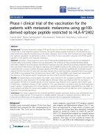
The state trajectories of this closed-loop system allow the
designing control law for WSC. As it can be seen on the left of
Fig. 3, constant gains of PI control produce not only inefficient
solution in terms of brake force, but can also produce traction
torque by electric motors. Considering these issues, VSPI control can be adjusted to have quicker dynamics in unstable area
(higher P contribution and lower I), while slower control action
should be produced in stable area (lower P contribution and
higher I). Therefore, it is proposed to switch between control
Fig. 3. State trajectories of wheel slip dynamics with PI and VSPI
WSC: PI control without switching logic (left) switching gains at reference
wheel slip (left) and gain scheduling of PI gain in stable and unstable
areas (right).
gains when the wheel slip passes reference value λ∗
Kp =
Kp1 , if λ < λ∗
Kp2 , otherwise
(8)
ta =
ta1 , if λ < λ∗
ta2 , otherwise
(9)
where Kp1 , Kp2 are proportional control gains, and ta1 , ta2
are tuning parameters of the integral control part. Presented
equations show how the gains are switched depending on the
wheel slip position in relation to the stability point of force-wheel
slip diagram.
The resulting system behavior is presented on the phase plane
in middle of Fig. 3. In this case, the system is driven to the origin
with a higher wheel slip rate in the area over the optimal slip to
avoid wheel locking. The wheel slip is held close to the optimum
in the area under the reference.
The system trajectories from Fig. 3 show that dynamics
depends on the vehicle velocity. Therefore, the scheduling of
P and I gains of VSPI control should be performed to achieve
a predictable system response. The right-hand side of Fig. 3
displays the trajectories after preliminary setting of the control
gains scheduled by the vehicle velocity variation. This provides predictable system behavior and allows obtaining the gain
scheduling curves for Kp and ta before experiments.
Additional tuning of the controller gains has been performed
using commercial vehicle dynamics simulation environment.
A set of straight-line braking maneuvers has been considered,
where initial velocity of the vehicle has been varied from 10 to
120 km/h with the step of 10 km/h. For each velocity case, offline
optimization was performed to find optimal values of the Kp1 ,
Kp2 and ta1 , ta2 using the genetic optimization algorithm [27].
Cost function for the optimization procedure was formulated as
follows:
Jcost = w1
sdist
+ w2
smax
+ w3
N
i=1
N
i=1
(λ∗ − λi )2
N −1
(ax − N1
N −1
N
i=1
ax )2
(10)
where sdist is the braking distance, smax is the maximal braking
distance obtained by considering vehicle without ABS, ax is
the vehicle longitudinal deceleration, and N is the number of
measuring points considering sampling rate of 1 ms.
The highest priority across driving safety, driving comfort,
and control quality has been given to the safety, and the lowest
SAVITSKI et al.: WSC FOR THE EV WITH IWMs: VARIABLE STRUCTURE AND SLIDING MODE METHODS
has been assigned to the comfort. This is possible to be done by
adjustment of corresponding weight coefficient w1 , w2 , and w3 ,
respectively.
It is proposed in this article to use the VSPI controller as the
continuous part. The discontinuous part can be presented as
Td = −Kism sign(s)
C. First-Order Sliding Mode (FOSM) Control
For this WSC variant, sliding variable σ is defined the same
as the control error
σ = λe = λ∗ − λ.
(11)
The control law for the classical sliding mode approach is
defined as
Tem = −Kfosm sign (σ)
(12)
with the control gain Kfosm as a positive constant.
Remark: To avoid chattering, which is critical for mechanical systems, sign function can be replaced with its following
approximation [28]:
ˆ [x(t)] =
sign
x(t)
|x(t)| +
h(x) = −rw Fz μroad (λ) + Tb,unc .
(15)
Finally, referring to [30], the following inequality should be
satisfied:
Kfosm ≥ |hmax |.
Td = T˙dfilt τd + Tdfilt .
(16)
Despite application of FOSM as the WSC is known from
various literature sources [31], this control technique was rarely
tested on the real EVs due to the issues with chattering. Despite
this disadvantage of the FOSM method, its feasibility by using
IWMs with a relatively high system bandwidth will be checked
and compared to other control techniques from this section.
(20)
Furthermore, the sliding surface consists of the two parts
σ = σ0 + z
(21)
where z is the integral term, and σ0 = λ∗ − λ is the sliding
variable.
On the next step, the derivative of the reference wheel slip is
subtracted that yields
Δλ˙ = λ˙ − λ˙ ∗ = −λ˙ ∗ − B(x)rw Fz μ(λ)
+ B(x)u + B(x)Tw,unc .
(14)
where B(x) is the input matrix. Then, the system uncertainty
h(x) is determined by
(19)
where Kism is the control gain of the discontinuous part.
The discontinuous control is, then, filtered for reduced chattering and a smoother control action. Following recommendations
from [32], a first-order linear filter can be used for this purpose.
Its tuning as well as the selection of the time constant τsw
are performed under a condition to avoid distorting the slow
component of the switched action
(13)
with a reasonably small value of > 0. Higher values of
can follow to the loss of control performance, which is characterized by occurrence of static error in presence of matched
disturbances [29].
The system uncertainty h(x) to be used in (13) can be obtained
from the wheel slip dynamics
λ˙ = B(x)(−rw Fz μroad (λ) + Tem + Tb,unc )
8539
(22)
Here, the known variable is the reference wheel slip λ∗ ,
f (x) = λ∗ , and the disturbance is the additional wheel torque
Tw,unc .
It can be finally derived that the auxiliary variable z equals to
z˙ = −
∂σ0
(−λ˙ ∗ + B(x)(uism − ud ))
∂(λ − λ∗ )
= λ˙ ∗ − B(x)(u − ud ).
(23)
The proof of stability of this ISM structure can be found
in [25].
E. Continuous Twisting Algorithm
D. Integral Sliding Mode
The ISM control method can ensure less chattering and also
provide compensation both of matched and unmatched disturbances. In the case of ISM implementation, the wheel slip
dynamics should be presented in the following form considering
uncertainties:
x˙ = f (x) + B(x)u + h(x), where |h(x)| < hmax .
(17)
The contributions of the ISM control effort are
Tem = Tc + Td
(18)
where Tc and Td are continuous and discrete control
contributions.
CTA relates to the sliding mode control methods and known
by its benefits in terms of disturbances compensation and solving
of chattering issue [33] and [34]. These advantages of the method
motivated its application for the WSC system, which has similar
design requirements: providing smooth wheel slip tracking and
robustness to disturbances. This control technique produces
third-order sliding mode in a relation system state. Hence, this
method cannot be naturally applied to the considered system. As
the solution, system order can be auxiliary increased. According
to definition of relative degree of freedom ρ [35], this corresponds to the minimum order of the time derivative of sliding
variable sρ , where control input Tem explicitly appears [23].
Computing first and second derivatives of the sliding variable,
8540
IEEE TRANSACTIONS ON INDUSTRIAL ELECTRONICS, VOL. 67, NO. 10, OCTOBER 2020
following representation of the system is obtained:
⎧
2
1 rw
rw
⎪
⎪
s
˙
=
−
Fx +
Tem
⎪
⎪
Vx Jw
Jw Vx
⎪
⎪
⎪
⎪
⎨
F˙ x rw ω Fx rw ω˙
r2 F˙ x
r2 Fx V x
să = ă w
+ w 2
Jw Vx
Jw Vx
mVx2
mVx2
⎪
⎪
⎪
⎪
⎪
2F r ω V˙
r V˙
r
⎪
⎪
⎩ + x w 3 x − w x2 Tem + w T˙em
mVx
Jw Vx
Jw Vx
. (24)
Right-hand side of the second equation in this system includes
several components, which cannot be estimated in a reliable way.
Hence, it is proposed to consider them as the system disturbance
w(t). Therefore, this auxiliary system can be presented in a
general form as
ζ˙1 (t) = ζ2 (t)
.
ζ˙2 (t) = w(t) + g(t)ν(t)
(25)
Presented system has two auxiliary states ζ1 = s and ζ2 = s˙
and ν represents auxiliary control input. Therefore, control effort
Tem is expressed as the integral of the auxiliary control input,
which provides continuous control input
τ2
Tem =
ν(t).
(26)
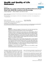
Fig. 4.
Wheel slip control with IWMs in low road friction conditions.
Fig. 5.
Distribution of the brake torque demand in frequency spectrum.
τ1
After obtaining this system description, control problem can
be formulated. This is concluded in driving the state ζ (which is
equal to the wheel slip error λe ) to the origin despite disturbances
that affect the system. To solve this problem, aforementioned
CTA can be applied as in [36]
1
ν (ζ) = −Kcta,1 ζ1 3 − Kcta,2 ζ2
η˙ = −Kcta,3 ζ1 0 − Kcta,4 ζ2 0
1
2
+η
(27)
where notation · γ means sign(·)| · |γ .
To guarantee stability of CTA control strategy, offline optimization of control gains can be performed. Method, described
in [36], was utilized for this purpose to confirm stability of the
system.
V. SIMULATION RESULTS
Before the implementation of the proposed wheel slip controllers on the vehicle demonstrator, they were investigated in
simulation to tune the parametrization. The simulation scenario corresponds to the test conditions of the proving track
at the University of Tokyo. The track has an inhomogeneous
low-friction surface composed from wet plastic sheets. For
this surface, the reference wheel slip was set as λ∗ = 0.04 for
the experimentally defined average tire-road friction coefficient
μ = 0.21. The initial braking velocity is 30 km/h for all tests.
The simulation diagrams are given in Figs. 4 and 5, where the
indices mark the wheels: FL—for the front left, FR—for the
front right, RL—for the rear left, and RR—for the rear right.
The analysis of simulation results allowed us to deduce the
following observations.
The VSPI control produces the highest value of the first wheel
slip peak that is caused by the integral part of the controller.
But, after the reaching of control setpoint, the further process is
characterized by sufficiently smooth and precise tracking of the
reference slip. The FOSM control demonstrates better agility
because the reference wheel slip is reached within a shorter
time as compared to other WSC variants. However, the overall
process is suffering from considerable chattering that can be
seen on the motor torque behavior, which is characterized by
oscillations with high amplitude and frequency (approx. 50
to 90 Hz). However, the IWMs used in this study provide a
direct torque transmission to the wheels and have sufficient
performance to realize the FOSM approach without damages of
driveline components. Such drawbacks, as the high first control
peak by VSPI method and the considerable chattering by the
SAVITSKI et al.: WSC FOR THE EV WITH IWMs: VARIABLE STRUCTURE AND SLIDING MODE METHODS
8541
TABLE II
WSC NUMERICAL EVALUATION FOR THE BRAKING IN
LOW FRICTION CONDITIONS WITH IWMS
FOSM method, are being eliminated in the case of the ISM wheel
slip controller. To achieve this effect, the ISM controller has
been tuned and its low-pass filter was designed with relatively
high cutoff frequency applicable for IWMs. The CTA control is
possessed of described advantages of the ISM variant but has, in
addition, a smoother dynamics of the motor torque demand. This
means that this control operates in relatively small frequencies
compared to the other control approaches, see Fig. 5.
To assess benefits of developed WSC strategies, RB approach [25] was used for comparison. For fair comparison of
control methods, RB approach was used in combination with
IWMs. Numerical evaluation of each control strategy is summarized in Table II.
These simulation studies allowed to fix the final design of all
four WSC variants and to realize them on the vehicle demonstrators for the proving track experiment. Their results are discussed
in next section.
VI. EXPERIMENTAL RESULTS
The experimental program considered the following factors.
The gains for four tested WSC variants were selected on the basis
of previous simulation studies with minimal tuning during the
tests. Due to track limitations, vehicle velocity around 25 k/h was
considered during vehicle tests. The proving track surface was
properly wetted before each trial to guarantee the consistency
of experiments and reach μroad ≈ 0.2. The braking maneuverer
were repeated about 40 times for each controller variant. The
experimental results are given in Fig. 6. The analysis of the tests
allowed us to draw the following observations.
VSPI control showed the worst tracking performance for the
front and rear wheels. Switching of the control gains at reference wheel slip point allows compensating difference in system
dynamics. However, this leads to more oscillatory behavior of
requested wheel torque. As a consequence, the first peak is
Fig. 6.
Wheel slip control with IWMs in low road friction conditions.
relatively high and the system oscillates with such amplitude
during the whole braking event. Despite this fact, the ride quality
did not suffer from these oscillations due to their relatively low
modulation frequency.
For the FOSM control, compared to the simulation results
with significant chattering and higher deviation from the reference value, these effect were attenuated during road tests.
Such high-frequency modulation of braking torque was not
bypassed by tires, which have first-order dynamics with lower
cutoff frequency. This effect led to better tracking performance
than in simulation, where transient tire dynamics were not
experimentally validated for this type of vehicle. Among other
control approaches, FOSM has shown the most agile reaction
during initial phase of WSC activation and the first peak for the
front and rear wheels has the lowest value. Nevertheless, FOSM
still produces oscillatory torque behavior, which has a negative
influence on the ride quality.
With PI control as the continuous control action, the ISM
approach demonstrated much better results in terms of tracking
performance and system adaptability compared to VSPI control.
Such system adaptability was guaranteed by discrete control part
responsible for disturbance rejection. ISM control provided ride
quality comparable with VSPI and CTA approaches.
The most precise and smooth control action was produced by
CTA algorithm due to the presence of integral control part and
subsequent integration of virtual input. Theoretically, this approach handles variation of the road conditions and vertical load
during the emergency that is confirmed experimentally for this
case. However, presence of the integral part leads to significantly
slower system reaction at the WSC activation stage. Hence, CTA
has the highest first peak for front and rear wheels. Nevertheless,
such progressive variation has huge benefits in terms of the ride
8542
IEEE TRANSACTIONS ON INDUSTRIAL ELECTRONICS, VOL. 67, NO. 10, OCTOBER 2020
TABLE III
WSC NUMERICAL EVALUATION FOR THE BRAKING IN
LOW FRICTION CONDITIONS WITH IWMS
Fig. 7. Experimental comparison of developed WSC control strategies
for the vehicle with IWMs. Note: Maximal value of the presented normalized metrics is 100% for each indicator that corresponds to the best
performance.
5) CTA can provides WSC solution applicable not only for
IWMs, but also to brake actuators with slower dynamics;
this is determined by smooth and progressive variation of
the braking torque demand.
VII. CONCLUSION
quality compared to torque modulation: CTA provides lowest
longitudinal vehicle jerk during emergency braking.
The final benchmark of the developed controllers is proposed
on the basis of the assessment criteria, which evaluate the
functionality of WSC by performance indicators related to the
vehicle dynamics. These assessment criteria are commonly used
in industrial practice [37], [38] by designing the traction and
braking control systems:
1) braking distance and mean deceleration to evaluate braking performance;
2) vehicle jerk to evaluate ride quality;
3) peak value of the initial WSC control cycle to evaluate
WSC agility and adaptability in terms of wheel slip
dynamics;
4) wheel slip RMSD to evaluate the system performance by
tracking the reference slip ratio.
The listed criteria are usually normalized to provide a comparison in percentages.
The test results are summarized in Table III and presented as
normalized criteria on the radar plot in Fig. 7. The following
observations can be done on the analysis of these data.
1) FOSM has the most agile reaction in WSC mode providing the lowest first peak.
2) Compared to the simulation results, FOSM braking torque
was filtered by tire longitudinal dynamics, which resulted
in precise wheel slip tracking.
3) Chattering in FOSM produced high-frequency braking
torque demand, which negatively influenced ride quality
during the WSC braking.
4) VSPI control produced the worst results in terms of
control and braking performance due to more oscillatory
brake torque demand modulation.
The presented work investigated four methods for the wheel
slip control using the sliding mode technique. These methods
were studied in simulation and experiment for full EV with
IWMs for each wheel. The following conclusions can be done
for each method from the analysis of obtained results.
1) Compared to the classical PI control formulation, the
VSPI control keeps the wheel slip in narrow area around
the reference value during the whole braking process.
2) VSPI control allows compensating unmatched disturbances, which are strongly dependent on the vehicle
velocity. This compensation can be realized with the
proposed gain scheduling method based on the nonlinear
wheel slip dynamics model.
3) FOSM has an advantage for the IWM control in terms
of easy tuning. However, the WSC process with FOSM
method is characterized by noticeable torque oscillations
that can be considered as a disadvantage from viewpoint
of the driving comfort.
4) As in the VSPI case, the ISM control can compensate unmatched uncertainties. In addition, the ISM-based WSC
operation has less oscillatory behavior and better braking
performance as compared to VSPI and FOSM variants.
5) The CTA provides smooth control signal and can be
potentially applied to the brake systems with a lower
bandwidth. However, tuning of this method is relatively
sophisticated. Nevertheless, the WSC with the CTA formulation achieved the best braking efficiency in both
simulation and experiment.
Summarizing, it should be concluded that the investigated
sliding mode techniques demonstrated promising results for the
WSC functions realized in EV with IWMs. In future works, the
authors are planning to advance the application of four developed
methods to further complex tasks related to the stability, ride,
and integrated chassis control.
SAVITSKI et al.: WSC FOR THE EV WITH IWMs: VARIABLE STRUCTURE AND SLIDING MODE METHODS
REFERENCES
[1] S. Murata, “Innovation by in-wheel-motor drive unit,” Veh. Syst. Dyn.,
vol. 50, no. 6, pp. 807–830, 2012. [Online]. Available: />1080/00423114.2012.666354
[2] E. Katsuyama, “Decoupled 3d moment control using in-wheel motors,”
Veh. Syst. Dyn., vol. 51, no. 1, pp. 18–31, 2013. [Online]. Available: https:
//doi.org/10.1080/00423114.2012.708758
[3] H. Kanchwala, P. L. Rodriguez, D. A. Mantaras, J. Wideberg, and
S. Bendre, “Obtaining desired vehicle dynamics characteristics with independently controlled in-wheel motors: State of art review,” SAE Int.
J. Passenger Cars-Mech. Syst., vol. 10, no. 2017-01-9680, pp. 413–425,
2017.
[4] V. Ivanov, D. Savitski, and B. Shyrokau, “A survey of traction control
and antilock braking systems of full electric vehicles with individually
controlled electric motors,” IEEE Trans. Veh. Technol., vol. 64, no. 9,
pp. 3878–3896, Sep. 2015.
[5] B. Wang, X. Huang, J. Wang, X. Guo, and X. Zhu, “A robust wheel slip
ratio control design combining hydraulic and regenerative braking systems
for in-wheel-motors-driven electric vehicles,” J. Franklin Inst., vol. 352,
no. 2, pp. 577–602, 2015.
[6] M. S. Basrah, E. Siampis, E. Velenis, D. Cao, and S. Longo, “Wheel slip
control with torque blending using linear and nonlinear model predictive
control,” Vehicle Syst. Dyn., vol. 55, no. 11, pp. 1665–1685, 2017. [Online].
Available: />[7] S. B. Choi, “Antilock brake system with a continuous wheel slip control
to maximize the braking performance and the ride quality,” IEEE Trans.
Control Syst. Technol., vol. 16, no. 5, pp. 996–1003, Sep. 2008.
[8] S. Semmler, R. Isermann, R. Schwarz, and P. Rieth, “Wheel slip control for
antilock braking systems using brake-by-wire actuators,” SAE Technical
Paper 2003-01-0325, pp. 1–8, 2003, doi: 10.4271/2003-01-0325.
[9] Dejun Yin and Yoichi Hori, “A new approach to traction control of EV
based on maximum effective torque estimation,” in Proc. 34th Annu. Conf.
IEEE Ind. Electron., Nov. 2008, pp. 2764–2769.
[10] J. Hu, D. Yin, Y. Hori, and F. Hu, “Electric vehicle traction control: A new
MTTE methodology,” IEEE Ind. Appl. Mag., vol. 18, no. 2, pp. 23–31,
Mar. 2012.
[11] J. Zhang, W. Sun, and H. Jing, “Nonlinear robust control of antilock braking systems assisted by active suspensions for automobile,”
IEEE Trans. Control Syst. Technol., vol. 27, no. 3, pp. 1352–1359,
May 2019.
[12] D. Savitski, V. Ivanov, B. Shyrokau, J. De Smet, and J. Theunissen,
“Experimental study on continuous ABS operation in pure regenerative
mode for full electric vehicle,” SAE Int. J. Passenger Cars-Mech. Syst.,
vol. 8, no. 2015-01-9109, pp. 364–369, 2015.
[13] C. Satzger, R. de Castro, A. Knoblach, and J. Brembeck, “Design and validation of an MPC-based torque blending and wheel slip control strategy,”
in Proc. IEEE Intell. Veh. Symp. (IV), Jun. 2016, pp. 514–520.
[14] Y. Ma, J. Zhao, H. Zhao, C. Lu, and H. Chen, “MPC-based slip ratio
control for electric vehicle considering road roughness,” IEEE Access,
vol. 7, pp. 52405–52413, 2019.
[15] M. S. Basrah, E. Siampis, E. Velenis, D. Cao, and S. Longo, “Wheel slip
control with torque blending using linear and nonlinear model predictive
control,” Veh. Syst. Dyn., vol. 55, no. 11, pp. 1665–1685, 2017.
[16] F. Pretagostini, B. Shyrokau, and G. Berardo, “Anti-lock braking control
design using a nonlinear model predictive approach and wheel information,” in Proc. IEEE Int. Conf. Mechatronics, Mar. 2019, vol. 1, pp. 525–
530.
[17] D. Tavernini et al., “An explicit nonlinear model predictive ABS controller
for electro-hydraulic braking systems,” IEEE Trans. Ind. Electron., to be
published, doi: 10.1109/TIE.2019.2916387.
[18] K. Han, M. Choi, B. Lee, and S. B. Choi, “Development of a traction
control system using a special type of sliding mode controller for hybrid
4WD vehicles,” IEEE Trans. Veh. Technol., vol. 67, no. 1, pp. 264–274,
Jan. 2018.
[19] K. Han, B. Lee, and S. B. Choi, “Development of an antilock brake system
for electric vehicles without wheel slip and road friction information,”
IEEE Trans. Veh. Technol., vol. 68, no. 6, pp. 5506–5517, Jun. 2019.
[20] R. Verma, D. Ginoya, P. Shendge, and S. Phadke, “Slip regulation for antilock braking systems using multiple surface sliding controller combined
with inertial delay control,” Veh. Syst. Dyn., vol. 53, no. 8, pp. 1150–1171,
2015.
[21] J. Zhang and J. Li, “Adaptive backstepping sliding mode control for wheel
slip tracking of vehicle with uncertainty observer,” Meas. Control, vol. 51,
no. 9-10, pp. 396–405, 2018.
8543
[22] S. De Pinto, C. Chatzikomis, A. Sorniotti, and G. Mantriota, “Comparison of traction controllers for electric vehicles with on-board drivetrains,” IEEE Trans. Veh. Technol., vol. 66, no. 8, pp. 6715–6727,
Aug. 2017.
[23] G. P. Incremona, E. Regolin, A. Mosca, and A. Ferrara, “Sliding mode
control algorithms for wheel slip control of road vehicles,” in Proc. Am.
Control Conf., 2017, pp. 4297–4302.
[24] D. Savitski, D. Schleinin, V. Ivanov, and K. Augsburg, “Individual wheel
slip control using decoupled electro-hydraulic brake system,” in Proc. 43rd
Annu. Conf. IEEE Ind. Electron. Soc., Oct. 2017, pp. 4055–4061.
[25] D. Savitski, D. Schleinin, V. Ivanov, and K. Augsburg, “Robust continuous
wheel slip control with reference adaptation: Application to the brake
system with decoupled architecture,” IEEE Trans. Ind. Informat., vol. 14,
no. 9, pp. 4212–4223, Sep. 2018.
[26] S. M. Savaresi and M. Tanelli, Active Braking Control Systems Design for
Vehicles. Berlin, Germany: Springer, 2010.
[27] R. Schaefer, Foundations of Global Genetic Optimization, vol. 74. Berlin,
Germany: Springer, 2007.
[28] G. Ambrosino, G. Celentano, and F. Garofalo, “Robust model tracking
control for a class of nonlinear plants,” IEEE Trans. Autom. Control,
vol. AC-30, no. 3, pp. 275–279, Mar. 1985.
[29] D. Efimov, A. Polyakov, L. Fridman, W. Perruquetti, and J.-P. Richard,
“Delayed sliding mode control,” Automatica, vol. 64, pp. 37–43, 2016.
[30] J. Dávila, L. Fridman, and A. Ferrara, “Introduction to sliding mode
control,” in Sliding Mode Control Vehicle Dynamics, 2017, Ch. 1, pp. 1–32.
[31] C. Unsal and P. Kachroo, “Sliding mode measurement feedback control
for antilock braking systems,” IEEE Trans. Control Syst. Technol., vol. 7,
no. 2, pp. 271–281, Mar. 1999.
[32] V. I. Utkin, Sliding Modes in Control and Optimization. Berlin, Germany:
Springer, 2013.
[33] V. Torres-González, T. Sanchez, L. M. Fridman, and J. A. Moreno, “Design
of continuous twisting algorithm,” Automatica, vol. 80, pp. 119–126,
2017.
[34] T. Sanchez, J. A. Moreno, and L. M. Fridman, “Output feedback continuous twisting algorithm,” Automatica, vol. 96, pp. 298–305, 2018.
[35] G. Bartolini, A. Pisano, E. Punta, and E. Usai, “A survey of applications of
second-order sliding mode control to mechanical systems,” Int. J. Control,
vol. 76, nos. 9/10, pp. 875–892, 2003.
[36] V. Torres-González, L. M. Fridman, and J. A. Moreno, “Continuous
twisting algorithm,” in Proc. IEEE 54th Ann. Conf. Decis. Control, 2015,
pp. 5397–5401.
[37] D. Savitski et al., “The new paradigm of an anti-lock braking system
for a full electric vehicle: Experimental investigation and benchmarking,”
Proc. Inst. Mech. Eng., Part D: J. Automobile Eng., vol. 230, no. 10,
pp. 1364–1377, 2016.
[38] H. A. Hamersma and P. S. Els, “ABS performance evaluation taking
braking, stability and steerability into account,” Int. J. Veh. Syst. Model.
Testing, vol. 12, nos. 3/4, pp. 262–283, 2017.
Dzmitry Savitski (S’12–M’18) received the
Dipl.-Ing. degree in automotive engineering
from Belarusian National Technical University,
Minsk, Belarus, in 2011, and Dr.-Ing. degree in
automotive engineering from the Technical University of Ilmenau, Ilmenau, Germany, in 2019.
From 2009 to 2011, he was a Research Assistant with the Division for Computer Vehicle
Design, Joint Institute of Mechanical Engineering, Minsk. From 2011 to 2018, he was working
as a Research Fellow with Automotive Engineering Group, Technical University of Ilmenau, Germany, focusing on
the vehicle dynamics and chassis control systems. In 2018, he joined
Knorr-Bremse Commercial Vehicle Systems GmbH, Schwieberdingen,
Germany, as a Development Engineer working on the topics of vehicle
stability control for highly automated trucks. He is currently a Lead Engineer with Arrival Germany GmbH, Dortmund, Germany, coordinating
control software development for the X-by-Wire chassis systems.
Dr. Savitski is a Member of the Association of German Engineers, the
Society of Automotive Engineers, and the Tire Society.
8544
IEEE TRANSACTIONS ON INDUSTRIAL ELECTRONICS, VOL. 67, NO. 10, OCTOBER 2020
Valentin Ivanov (M’13–SM’15) received the
Ph.D. and D.Sc. degrees in automotive engineering from Belarusian National Technical
University, Minsk, Belarus, in 1997 and 2006,
respectively, and the Dr.-Ing. habil. degree in
automotive engineering from the Technical University of Ilmenau, Ilmenau, Germany, in 2017.
From 1995 to 2007, he was consequently
an Assistant Professor, an Associated Professor, and a Full Professor with the Department
of Automotive Engineering, Belarusian National
Technical University. In July 2007, he became an Alexander von Humboldt Fellow, and in July 2008, he became a Marie Curie Fellow with the
Technical University of Ilmenau. He is currently EU Project Coordinator
with the Automotive Engineering Group, Technical University of Ilmenau.
His research interests include vehicle dynamics, electric vehicles, automotive control systems, chassis design, and fuzzy logic.
Prof. Ivanov is an Society of Automotive Engineers (SAE) Fellow
and a Member of the Society of Automotive Engineers of Japan, the
Association of German Engineers, the International Federation of Automatic Control (Technical Committee “Automotive Control”), and the
International Society for Terrain-Vehicle Systems.
Klaus Augsburg received the Dr.-Ing. degree
in automotive engineering from the Dresden
University of Technology, Dresden, Germany, in
1985.
From 1984 to 1993, he worked in industry
on leading engineer positions, and then, as a
Senior Research Assistant with the Dresden
University of Technology, Dresden, Germany, in
1993–1999. In 1999, he became a Full Professor and the Chair of the Automotive Engineering Group, Technical University of Ilmenau,
Ilmenau, Germany. He is also the Chairman of Workgroup Automotive Engineering Verein Deutscher Ingenieure (VDI) Thringen and the
Chief Executive Officer of Steinbeis-Transferzentrum Fahrzeugtechnik.
He founded the Thuringian Centre of Innovation in Mobility in 2011,
where he is coordinating public research projects and bilateral projects
with industrial partners.
Prof. Augsburg is a Member of the Association of German Engineers.
Tomoki Emmei (S’15) received the B.S. and
M.S. degrees in science from the University of
Tokyo, Tokyo, Japan, in 2015 and 2017, respectively. He is currently working toward the Ph.D.
degree with the Department of Electrical Engineering and Information Systems, the University
of Tokyo.
He is also a Research Fellow with the Japan
Society for the Promotion of Science from 2018
(JSPS-DC2). His research interest includes motion control and electric vehicle control.
Mr. Emmei received the IEEJ Young Researcher’s Award in 2015
and the Dean’s Award for Outstanding Achievement from the Graduate
School of Frontier Sciences and Faculty of Engineering, the University
of Tokyo in 2017 and 2015 respectively.
Hiroyuki Fuse received the B.Eng. degree in
electrical and electronic engineering from the
Tokyo Institute of Technology, Tokyo, Japan, in
2017, and the M.S. degree in advanced energy
from the University of Tokyo, Tokyo, Japan, in
2019. He is currently working toward the Ph.D.
degree with the Department of Advanced Energy, the University of Tokyo.
His current research interests include vehicle dynamics, and motion control of electric
vehicle.
Mr. Fuse received the JSAE Graduate School Research Award from in
2019, IEEJ Excellent Presentation Award in 2019, and the Deans Award
for Outstanding Achievement from the Graduate School of Frontier Sciences and Faculty of Engineering, the University of Tokyo in 2019. He is
a Student Member of IEE of Japan and Society of Automotive Engineers
(SAE) of Japan, respectively.
Hiroshi Fujimoto (S’99–M’01–SM’12) received
the Ph.D. degree in electrical engineering from
the Department of Electrical Engineering, University of Tokyo, Tokyo, Japan, in 2001.
In 2001, he joined the Department of
Electrical Engineering, Nagaoka University of
Technology, Niigata, Japan, as a Research Associate. From 2002 to 2003, he was a Visiting
Scholar with the School of Mechanical Engineering, Purdue University, West Lafayette, IN,
USA. In 2004, he joined the Department of Electrical and Computer Engineering, Yokohama National University, Yokohama, Japan, as a Lecturer and he became an Associate Professor
in 2005. He is currently an Associate Professor with the Department
of Advanced Energy, Graduate School of Frontier Sciences, University
of Tokyo since 2010. His research interests include control engineering,
motion control, nano-scale servo systems, electric vehicle control, motor
drive, visual servoing, and wireless motors.
Prof. Fujimoto received the Best Paper Awards from the IEEE Transactions on Industrial Electronics in 2001 and 2013, Isao Takahashi
Power Electronics Award in 2010, Best Author Prize of the Society of
Instrument and Control Engineers (SICE) in 2010, the Nagamori Grand
Award in 2016, and First Prize Paper Award IEEE Transactions on Power
Electronics in 2016. He is a Senior Member of IEE of Japan. He is also
a member of the Society of Instrument and Control Engineers, Robotics
Society of Japan, and Society of Automotive Engineers of Japan. He is
an Associate Editor of the IEEE/ASME TRANSACTIONS ON MECHATRONICS
from 2010 to 2014, IEEE Industrial Electronics Magazine from 2006,
IEE of Japan Transactions on Industrial Application from 2013, and
Transactions on SICE from 2013 to 2016. He is a Chairperson of the
Society of Automotive Engineers of Japan (JSAE) vehicle electrification
committee from 2014 and a past chairperson of IEEE/IES Technical
Committee on Motion Control from 2012 to 2013.
Leonid M. Fridman received the M.S. degree
in mathematics from Kuibyshev (Samara) State
University, Samara, Russia, in 1976, the Ph.D.
degree in applied mathematics from the Institute
of Control Science, Moscow, Russia, in 1988,
and the Dr.Sc. degree in control science from
the Moscow State University of Mathematics
and Electronics, Moscow, Russia, in 1998.
From 1976 to 1999, he was with the Department of Mathematics, Samara State Architecture and Civil Engineering University. From 2000
to 2002, he was with the Department of Postgraduate Study and Investigations, Chihuahua Institute of Technology, Chihuahua, Mexico. In 2002,
he joined the Department of Control Engineering and Robotics, Division
of Electrical Engineering of Engineering Faculty, National Autonomous
University of Mexico, Mexico City, Mexico. His research interest includes
variable structure systems. He has coauthored and has been a CoEditor for ten books and 17 special issues devoted to the sliding mode
control.
Prof. Fridman served from 2014 to 2018 as a Chair of Technical
Committee (TC) on Variable Structure and Sliding Mode Control of IEEE
Control Systems Society. He was a recipient of a Scopus prize for the
best cited Mexican Scientists in Mathematics and Engineering 2010. He
served and serves as an Associated Editor in different leading journals
of control theory and applied mathematics. He was working as an Invited
Professor in more than 20 universities and research laboratories of
Argentina, Australia, Austria, China, France, Germany, Italy, Israel, and
Spain. Actually he is also an International Chair of Institut National de
Recherche en Informatique et en Automatique (INRIA), France, and a
High-Level Foreign Expert of Ministry of Education of China.