Tài liệu Structured Cabling Supplement doc
Bạn đang xem bản rút gọn của tài liệu. Xem và tải ngay bản đầy đủ của tài liệu tại đây (2.46 MB, 125 trang )
Sponsored by:
Structured Cabling
Supplement
Cisco Networking Academy Program
CCNA 1: Networking Basics v3.0
Objectives
The Structured Cabling Supplement for CCNA provides curriculum
and laboratory exercises in seven areas:
a. Structured Cabling Systems
b. Structured Cabling Standards and Codes
c. Safety
d. Tools of the Trade
e. Installation Process
f. Finish Phase
g. The Cabling Business
This material and the associated labs provide a broad introduction to
structured cabling installation.
The section on Structured Cabling Systems discusses the rules and
subsystems of structured cabling for a local-area network (LAN). A
LAN is defined as a single building or group of buildings in a campus
environment in close proximity to one another, typically less than two
square kilometers or one square mile. This supplement starts at the
demarcation point, works through the various equipment rooms, and
continues to the work area. The issue of scalability is also addressed.
The learning objectives for Structured Cabling Systems are as
follows:
1.1 Rules of Structured Cabling for LANs
1.2 Subsystems of Structured Cabling
1.3 Scalability
1.4 Demarcation Point
1.5 Telecommunications and Equipment Rooms
1.6 Work Areas
1.7 MC, IC, and HC
The section on Structured Cabling Standards and Codes introduces
the standards-setting organizations that establish the guidelines used
by cabling specialists. Important information about these international
standards organizations is included.
2 - 125 CCNA 1: Networking Basics v3.0 – Structured Cabling Supplement Copyright 2003, Cisco Systems, Inc.
The learning objectives for Structured Cabling Systems and Codes
are as follows:
2.1 Telecommunications Industry Association (TIA) and Electronic
Industries Association (EIA)
2.2 European Committee for Electrotechnical Standardization
(CENELEC)
2.3 International Organization for Standardization (ISO)
2.4 Codes for the United States
2.5 Evolution of Standards
The Safety section contains important information that is often
overlooked when discussing low voltage telecommunications wiring.
Students that are not accustomed to working in the physical
workplace will benefit from the labs and training in this section.
The learning objectives for Safety are as follows:
3.1 Safety Codes and Standards for the United States
3.2 Safety Around Electricity
3.3 Lab and Workplace Safety Practices
3.4 Personal Safety Equipment
The Tools of the Trade section discusses how various tools can help
turn a difficult job with ordinary results into a simple job with
outstanding results. This module gives students hands-on experience
using several of the tools that telecommunications cabling installers
rely on for professional results.
The learning objectives for Tools of the Trade are as follows:
4.1 Stripping and Cutting Tools
4.2 Termination Tools
4.3 Diagnostic Tools
4.4 Installation Support Tools
The Installation Process section describes the elements of an
installation. This chapter begins with the rough-in phase, when the
cables are pulled into place. This section also discusses riser or
backbone cables, the fire-stops used when a wire passes through a fire
rated wall, copper terminations, and fixtures such as wall adapters.
3 - 125 CCNA 1: Networking Basics v3.0 – Structured Cabling Supplement Copyright 2003, Cisco Systems, Inc.
The learning objectives for Installation Process are as follows:
5.1 Rough-In Phase
5.2 Vertical Backbone and Horizontal Cable Installation
5.3 Fire-Stops
5.4 Terminating Copper Media
5.5 The Trim Out Phase
The Finish Phase section discusses the point at which installers test
and sometimes certify their work. Testing ensures that all the wires
route to their appointed destination. Certification ensures that the
quality of the wiring and connection meet industry standards.
The learning objectives for Finish Phase are as follows:
6.1 Cable Testing
6.2 Time Domain Reflectometer (TDR)
6.3 Cable Certification and Documentation
6.4 Cutting Over
The Cabling Business section discusses the business side of the
industry. Before cables can be installed, there must be a bid. Before
there can be a bid, there must be a request for a proposal, and several
meetings and walk-throughs to determine the scope of the work.
Documentation may be required to describe the project and show how
it was built. Licenses and union membership may also be required to
perform the work. All projects must be performed in a timely manner
with minimal waste of materials. This usually requires project
planning and program management applications.
The learning objectives for The Cabling Business are as follows:
7.1 Site Survey
7.2 Labor Situations
7.3 Contract Revision and Signing
7.4 Project Planning
7.5 Final Documentation
Lab exercises give students the opportunity to practice the manual
skills portion of structured cabling installation.
4 - 125 CCNA 1: Networking Basics v3.0 – Structured Cabling Supplement Copyright 2003, Cisco Systems, Inc.
1 Structured Cabling Systems
1.1 Rules of Structured Cabling for LANs
Structured cabling is a systematic approach to cabling. It is a method
for creating an organized cabling system that can be easily
understood by installers, network administrators, and any other
technicians that deal with cables.
There are three rules that will help ensure the effectiveness and
efficiency of structured cabling design projects.
The first rule is to look for a complete connectivity solution. An
optimal solution for network connectivity includes all the systems
that are designed to connect, route, manage, and identify cables in
structured cabling systems. A standards-based implementation is
designed to support both current and future technologies. Following
the standards will help ensure the long-term performance and
reliability of the project.
The second rule is to plan for future growth. The number of cables
installed should also meet future requirements. Category 5e, Category
6, and fiber-optic solutions should be considered to ensure that future
needs will be met. The physical layer installation plan should be
capable of functioning for ten or more years.
The final rule is to maintain freedom of choice in vendors. Even
though a closed and proprietary system may be less expensive
initially, this could end up being much more costly over the long
term. A non-standard system from a single vendor may make it more
difficult to make moves, adds, or changes at a later time.
Web Link:
/>sol_pm_markets/Finance/rules.asp
5 - 125 CCNA 1: Networking Basics v3.0 – Structured Cabling Supplement Copyright 2003, Cisco Systems, Inc.
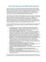
1.2 Subsystems of Structured Cabling
Figure 1 Subsystems of Structured Cabling
There are seven subsystems associated with the structured cabling
system, as shown in Figure 1. Each subsystem performs certain
functions to provide voice and data services throughout the cable
plant:
• Demarcation point (demarc) within the entrance facility (EF)
in the equipment room
• Equipment room (ER)
• Telecommunications room (TR)
• Backbone cabling, which is also known as vertical cabling
• Distribution cabling, which is also known as horizontal
cabling
• Work area (WA)
• Administration
The demarc is where the outside service provider cables connect to
the customer cables in the facility. Backbone cabling is the feeder
cables that are routed from the demarc to the equipment rooms and
then on to the telecommunications rooms throughout the facility.
Horizontal cabling distributes cables from the telecommunication
rooms to the work areas. The telecommunications rooms are where
connections take place to provide a transition between the backbone
cabling and horizontal cabling.
6 - 125 CCNA 1: Networking Basics v3.0 – Structured Cabling Supplement Copyright 2003, Cisco Systems, Inc.
These subsystems make structured cabling a distributed architecture
with management capabilities that are limited to the active
equipment, such as PCs, switches, hubs, and so forth. Designing a
structured cabling infrastructure that properly routes, protects,
identifies, and terminates the copper or fiber media is absolutely
critical for network performance and future upgrades.
1.3 Scalability
A LAN that can accommodate future growth is referred to as a
scalable network. It is important to plan ahead when estimating the
number of cable runs and cable drops in a work area. It is better to
install extra cables than to not have enough.
In addition to pulling extra cables in the backbone area for future
growth, an extra cable is generally pulled to each workstation or
desktop. This gives protection against pairs that may fail on voice
cables during installation, and it also provides for expansion. It is also
a good idea to provide a pull string when installing the cables to make
it easier for adding cables in the future. Whenever new cables are
added, a new pull string should also be added
1.3.1 Backbone scalability
When deciding how much extra copper cable to pull, first determine
the number of runs that are currently needed and then add
approximately 20 percent of extra cable.
A different way to obtain this reserve capability is to use fiber-optic
cabling and equipment in the building backbone. For example, the
termination equipment can be updated by inserting faster lasers and
drivers to accommodate fiber growth.
7 - 125 CCNA 1: Networking Basics v3.0 – Structured Cabling Supplement Copyright 2003, Cisco Systems, Inc.
1.3.2 Work area scalability
Figure 1 Allow for Growth
Each work area needs one cable for voice and one for data. However,
other devices may need a connection to either the voice or the data
system. Network printers, FAX machines, laptops, and other users in
the work area may all require their own network cable drops.
After the cables are in place, use multiport wall plates over the jacks.
There are many possible configurations for modular furniture or
partition walls. Color-coded jacks can be used to simplify the
identification of circuit types, as shown in Figure 1. Administration
standards require that every circuit should be clearly labeled to assist
in connections and troubleshooting.
A new technology that is becoming popular is Voice over Internet
Protocol (VoIP). This technology allows special telephones to use
data networks when placing telephone calls. A significant advantage
of this technology is the avoidance of costly long distance charges
when VoIP is used over existing network connections. Other devices
like printers or computers can be plugged into the IP phone. The IP
phone then becomes a hub or switch for the work area. Even if these
types of connections are planned, enough cables should be installed to
allow for growth. Especially consider that IP telephony and IP video
traffic may share the network cables in the future.
To accommodate the changing needs of users in offices, it is
recommended to provide at least one spare cable to the work area
outlet. Offices may change from single user to multiuser spaces. This
can result in an inefficient work area if only one set of
communication cables was pulled. Assume that every work area will
accommodate multiple users in the future.
8 - 125 CCNA 1: Networking Basics v3.0 – Structured Cabling Supplement Copyright 2003, Cisco Systems, Inc.
1.4 Demarcation Point
Figure 1 Demarcation Point
The demarcation point (demarc), shown in Figure 1, is the point at
which outdoor cabling from the service provider connects to the
intrabuilding backbone cabling. It represents the boundary between
the responsibility of the service provider and the responsibility of the
customer. In many buildings, the demarc is near the point of presence
(POP) for other utilities such as electricity and water.
The service provider is responsible for everything from the demarc
out to the service provider facility. Everything from the demarc into
the building is the responsibility of the customer.
The local telephone carrier is typically required to terminate cabling
within 15 m (49.2 feet) of building penetration and to provide
primary voltage protection. The service provider usually installs this.
The Telecommunications Industry Association (TIA) and Electronic
Industries Alliance (EIA) develop and publish standards for many
industries, including the cabling industry. To ensure that the cabling
is safe, installed correctly, and retains performance ratings, these
standards should be followed during any voice or data cabling
installation or maintenance.
The TIA/EIA-569-A standard specifies the requirements for the
demarc space. The standards for the structure and size of the demarc
space are based on the size of the building. In buildings larger than
2,000 square meters (21,528 sq ft), a locked, dedicated, and enclosed
room is recommended.
9 - 125 CCNA 1: Networking Basics v3.0 – Structured Cabling Supplement Copyright 2003, Cisco Systems, Inc.
The following are general guidelines for setting up a demarcation
point space:
• Allow 1 square meter (10.8 sq feet) of plywood wall mount
for each 20-square meter (215.3-sq feet) area of floor space
• Cover the surfaces where the distribution hardware is
mounted with fire-rated plywood or plywood that is painted
with two coats of fire retardant paint
• Either the plywood or the covers for the termination
equipment should be colored orange to indicate the point of
demarcation.
1.5 Telecommunications and Equipment Rooms
Figure 1 Telecommunications Room
10 - 125 CCNA 1: Networking Basics v3.0 – Structured Cabling Supplement Copyright 2003, Cisco Systems, Inc.
Figure 2 Panduit Distribution Rack
After the cable enters the building through the demarc, it travels to
the entrance facility (EF), which is usually in the equipment room
(ER). The equipment room is the center of the voice and data
network. An equipment room is essentially a large
telecommunications room that may house the main distribution
frame, network servers, routers, switches, the telephone PBX,
secondary voltage protection, satellite receivers, modulators, high
speed Internet equipment, and so on. The design aspects of the
equipment room are specified in the TIA/EIA-569-A standard.
In larger facilities, the equipment room may feed one or more
telecommunications rooms (TR) that are distributed throughout the
building. The TRs contains the telecommunications cabling system
equipment for a particular area of the LAN such as a floor or part of a
floor, as shown in Figure 1. This includes the mechanical
terminations and cross-connect devices for the horizontal and
backbone cabling system. Departmental or workgroup switches, hubs,
and routers are commonly located in the TR.
A wiring hub and patch panel in a TR may be mounted to a wall with
a hinged wall bracket, a full equipment cabinet, or a distribution rack
as shown in Figure 1.
A hinged wall bracket must be attached to the plywood panel that it
covers the underlying wall surface. The hinge allows the assembly to
swing out so that technicians can easily access the backside of the
wall. It is important to allow 48 cm (19 inches) for the panel to swing
out from the wall.
A distribution rack must have a minimum of 1 meter (3 feet) of
workspace clearance in the front and rear of the rack. A 55.9-cm (22-
inch) floor plate is used to mount the distribution rack. The floor plate
11 - 125 CCNA 1: Networking Basics v3.0 – Structured Cabling Supplement Copyright 2003, Cisco Systems, Inc.
will provide stability and determine the minimum distance for the
final position of the distribution rack. A distribution rack is shown in
Figure 2.
A full equipment cabinet requires at least 76.2 cm (30 inches) of
clearance in front for the door to swing open. Equipment cabinets are
generally 1.8-m (5.9-feet) high, 0.74-m (2.4-feet) wide, and 0.66-m
(2.16-feet) deep.
When placing equipment into equipment racks, consider whether or
not the equipment uses electricity. Other considerations include cable
routing, cable management, and ease of use. For example, a patch
panel should not be placed high on a rack if a significant number of
changes will occur after the installation. Heavier equipment such as
switches and servers should be placed near the bottom of the rack for
stability.
Scalability that allows for future growth is another consideration in an
equipment layout. The initial layout should include extra rack space
for future patch panels or extra floor space for future rack
installations.
Proper installation of equipment racks and patch panels in the TR will
allow for easy modifications to the cabling installation in the future.
1.6 Work Areas
Figure 1 Work Areas
A work area is the area serviced by an individual TR. A work area
usually occupies one floor or part of one floor of a building, as shown
in Figure 1.
12 - 125 CCNA 1: Networking Basics v3.0 – Structured Cabling Supplement Copyright 2003, Cisco Systems, Inc.
The maximum distance for a cable from the termination point in the
TR to the termination at the work area outlet must not exceed 90
meters (295 feet). This 90 meter maximum horizontal cabling
distance is referred to as the permanent link. Each work area must
have at least two cables. One for data and the other for voice. As
previously discussed, accommodations for other services and future
expansion must also be considered.
Because most cables cannot be strung across the floor, cables are
usually contained in wire management devices such as trays, baskets,
ladders, and raceways. Many of these devices will route the paths of
the wires in the plenum areas above suspended ceilings. The ceiling
height must then be multiplied by two and subtracted from the
maximum work area radius to allow for wiring to and from the wire
management device.
ANSI/TIA/EIA-568-B specifies that there can be 5 m (16.4 feet) of
patch cord to interconnect equipment patch panels, and 5 m (16.4
feet) of cable from the cable termination point on the wall to the
telephone or computer. This additional maximum of 10 meters (33
feet) of patch cords added to the permanent link is referred to as the
horizontal channel. The maximum distance for a channel is 100
meters (328 feet), the 90-meter (295 feet) maximum permanent link
plus 10 meters (33 feet) maximum of patch cords.
Other factors may decrease the work area radius. For example, the
cable routes may not lead straight to the destination. The location of
heating, ventilation, and air conditioning equipment, power
transformers and lighting equipment may dictate paths that add
length. After everything is taken into account, a maximum radius of
100 m (328 feet) may be closer to 60 m (197 feet). A work area
radius of 50 m (164 feet) is commonly used for design purposes.
1.6.1 Servicing the work area
Figure 1 Servicing the Work Areas
13 - 125 CCNA 1: Networking Basics v3.0 – Structured Cabling Supplement Copyright 2003, Cisco Systems, Inc.
Patching is helpful when connectivity changes occur frequently. It is
much easier to patch a cable from the work area outlet to a new
position in the TR than it is to remove terminated wires from
connected hardware and reterminate them to another circuit. Patch
cords are also used to connect networking equipment to the cross-
connects in a TR. Patch cords are limited by the TIA/EIA-568-B.1
standard to 5 m (16.4 feet).
A uniform wiring scheme must be used throughout a patch panel
system. For example, if the T568-A wiring plan is used for
information outlets or jacks, T568-A patch panels should be used.
The same is true for the T568-B wiring plan.
Patch panels can be used for Unshielded Twisted Pair (UTP),
Shielded Twisted Pair (STP), or, if mounted in enclosures, fiber-optic
connections. The most common patch panels are for UTP. These
patch panels use RJ-45 jacks. Patch cords, usually made with
stranded cable to increase flexibility, connect to these plugs.
In most facilities, there is no provision to keep authorized
maintenance personnel from installing unauthorized patches or
installing an unauthorized hub into a circuit. There is an emerging
family of automated patch panels which can provide extensive
network monitoring in addition to simplifying the provisioning of
moves, adds, and changes. These patch panels normally provide an
indicator lamp over any patch cord that needs to be removed, and
then once the cord is released, provides a second light over the jack to
which they should be reaffixed. In this way the system can
automatically guide a relatively unskilled employee through moves,
adds, and changes.
The same mechanism that detects when the operator has moved a
given jack will also detect when a jack has been pulled. An
unauthorized resetting of a patch can trigger an event in the system
log, and if need be trigger an alarm. For instance, if a half-dozen
wires to the work area suddenly show up as being open at 2:30 in the
morning, this is an event worth looking into, as theft may be
occurring.
14 - 125 CCNA 1: Networking Basics v3.0 – Structured Cabling Supplement Copyright 2003, Cisco Systems, Inc.
1.6.2 Types of patch cables
Figure 1 UTP Patch Cable
Patch cables come in a variety of wiring schemes. The straight-
through cable is the most common patch cable. It has the same wiring
scheme on both ends of the cable. Therefore, a pin on one end is
connected to the corresponding pin number on the other end. These
types of cables are used to connect PCs to a network, a hub, or a
switch.
When connecting a communications device such as a hub or switch to
an adjacent hub or switch, a crossover cable is typically used.
Crossover cables use the T568-A wiring plan on one end and T568-B
on the other end.
Lab 1: Examination of Termination Types
15 - 125 CCNA 1: Networking Basics v3.0 – Structured Cabling Supplement Copyright 2003, Cisco Systems, Inc.
1.6.3 Cable management
Figure 1 Panduit Rack-Mounted Vertical and Horizontal Cable
Management System
Cable management devices are used to route cables along a neat and
orderly path and to assure minimum bend radius is maintained. Cable
management also simplifies cable additions and modification to the
wiring system.
There are many options for cable management in a TR. Cable baskets
can be used for easy, lightweight installations. Ladder racks are often
used to support heavy loads of bundled cable. Different types of
conduits can be used to run cable inside walls, ceilings, floors, or to
shield them from external conditions. Cable management systems are
used vertically and horizontally on telecommunications racks to
distribute cable neatly, as shown in Figure 1.
16 - 125 CCNA 1: Networking Basics v3.0 – Structured Cabling Supplement Copyright 2003, Cisco Systems, Inc.
1.7 MC, IC, and HC
Figure 1 MC, HC, and IC Planning
Most networks have multiple TRs for various reasons. If a network is
spread over many floors or buildings, a TR is needed for each floor of
each building. Media can only travel a certain distance before the
signal starts to degrade or attenuate. Therefore, TRs are located at
defined distances throughout the LAN to provide interconnects and
cross-connects to hubs and switches to assure desired network
performance. These TRs house equipment such as repeaters, hubs,
bridges, or switches that are needed to regenerate the signals.
The primary TR is referred to as the main cross-connect (MC). The
MC is the center of the network. This is where all the wiring
originates and where most of the equipment is located. The
intermediate cross-connect (IC) is connected to the MC and may hold
the equipment for a building on a campus. The horizontal cross-
connect (HC) provides the cross-connect between the backbone and
horizontal cables on a single floor of a building.
17 - 125 CCNA 1: Networking Basics v3.0 – Structured Cabling Supplement Copyright 2003, Cisco Systems, Inc.
1.7.1 Main cross-connect (MC)
Figure 1 MC, HC, and IC
Figure 2 Connecting the MC to the IC and HCs
The MC is the main concentration point of a building or campus. It is
the room that controls the rest of the TRs in a location. In some
networks, it is where the cable plant connects to the outside world, or
the demarc.
All ICs and HCs are connected to the MC in a star topology.
Backbone, or vertical, cabling is used to connect ICs and HCs on
different floors. If the entire network is confined to a single multi-
18 - 125 CCNA 1: Networking Basics v3.0 – Structured Cabling Supplement Copyright 2003, Cisco Systems, Inc.
story building, the MC is usually located on one of the middle floors,
even if the demarc is located in an entrance facility on the first floor
or in the basement.
The backbone cabling runs from the MC to each of the ICs. The red
lines in Figure 1 represent the backbone cabling. The ICs are located
in each of the campus buildings, and the HCs serve work areas. The
black lines represent horizontal cabling from the HCs to the work
areas.
For campus networks in multiple buildings, the MC is usually located
in one building. Each building typically has its own version of the
MC called the intermediate cross-connect (IC). The IC connects all
the HCs within the building. It also enables the extension of backbone
cabling from the MC to each HC because this interconnection point
does not degrade the communications signals.
As shown in Figure 2, there may only be one MC for the entire
structured cabling installation. The MC feeds the ICs. Each IC feeds
multiple HCs. There can only be one IC between the MC and any
HC.
1.7.2 Horizontal cross-connect (HC)
Figure 1 Horizontal Cabling and Symbols
The horizontal cross-connect (HC) is the TR closest to the work
areas. The HC is typically a patch panel or punch down block. The
HC may also contain networking devices such as repeaters, hubs, or
switches. It can be rack mounted in a room or in a cabinet. Since a
typical horizontal cable system includes multiple cable runs to each
workstation, it can represent the largest concentration of cable in the
19 - 125 CCNA 1: Networking Basics v3.0 – Structured Cabling Supplement Copyright 2003, Cisco Systems, Inc.
building infrastructure. A building with 1,000 workstations may
contain a horizontal cable system with 2,000 to 3,000 cable runs.
Horizontal cabling includes the copper or optical fiber networking
media that is used from the wiring closet to a workstation, as shown
in Figure 1. Horizontal cabling also includes the networking media
that runs along a horizontal pathway that leads to the
telecommunications outlet, and the patch cords, or jumpers in the HC.
Any cabling between the MC and another TR is backbone cabling.
The difference between horizontal and backbone cabling is defined in
the standards.
Lab 2: Terminating a Category 5e Cable on a Category 5e Patch
Panel
1.7.3 Backbone cabling
Any cabling installed between the MC and another TR is known as
backbone cabling. The difference between horizontal and backbone
cabling is clearly defined in the standards. Backbone cabling is also
referred to as vertical cabling. It consists of backbone cables,
intermediate and main cross-connects, mechanical terminations, and
patch cords or jumpers used for backbone-to-backbone cross-
connection. Backbone cabling includes the following:
• TRs on the same floor, MC to IC, and IC to HC
• Vertical connections, or risers, between TRs on different
floors, such as MC to IC cabling
• Cables between TRs and demarcation points
• Cables between buildings, or inter-building cables, in a multi-
building campus
The maximum distance for cabling runs depends on the type of cable
installed. For backbone cabling, the maximum distance can also be
affected by how the cabling will be used. For example, if single-mode
fiber-optic cable will be used to connect the HC to the MC, then the
maximum distance for the backbone cabling run is 3000 m (9842.5
feet).
Sometimes the maximum distance of 3000 m (9842.5 feet) must be
split between two sections. For example, if the backbone cabling will
connect the HC to an IC and the IC to the MC. When this occurs, the
maximum distance for the backbone cabling run between the HC and
the IC is 300 m (984 feet). The maximum distance for the backbone
cabling run between the IC and the MC is 2700 m (8858 feet).
20 - 125 CCNA 1: Networking Basics v3.0 – Structured Cabling Supplement Copyright 2003, Cisco Systems, Inc.
1.7.4 Fiber-optic backbone
The use of fiber optics is an effective way to move backbone traffic
for three reasons:
• Optical fibers are impervious to electrical noise and radio
frequency interference.
• Fiber does not conduct currents that can cause ground loops.
• Fiber-optic systems have high bandwidth and can work at
high speeds.
A fiber-optic backbone can also be upgraded to provide even greater
performance when the terminal equipment is developed and becomes
available. This can make fiber optics very cost effective.
An additional advantage is that fiber can travel much farther than
copper when used as a backbone media. Multimode optical fiber can
cover lengths of up to 2000 meters (6561.7 feet). Single-mode fiber-
optic cables can cover up to 3000 meters (9842.5 feet). Optical fiber,
especially single mode fiber, can carry signals much farther.
Distances of 96.6 to 112.7 km (60 to 70 miles) are possible,
depending on terminal equipment. However, these longer distances
are beyond the scope of the LAN standards.
1.7.5 MUTOAs and Consolidation Points
Figure 1 Typical MUTOA Installation
21 - 125 CCNA 1: Networking Basics v3.0 – Structured Cabling Supplement Copyright 2003, Cisco Systems, Inc.
Figure 2 Typical Consolidation Point Installation
Additional specifications for horizontal cabling in work areas with
moveable furniture and partitions have been included in TIA/EIA-
568-B.1. Horizontal cabling methodologies using multiuser
telecommunications outlet assemblies (MUTOAs) and consolidation
points (CPs) are specified for open office environments. These
methodologies provide increased flexibility and economy for
installations that require frequent reconfiguration.
Rather than replacing the entire horizontal cabling system feeding
these areas, a CP or MUTOA can be located close to the open office
area and eliminate the need to replace the cabling all the way back to
the TR whenever the furniture is rearranged. The cabling only needs
to be replaced between the new work area outlets and the CP or
MUTOA. The longer distance of cabling back to the TR remains
permanent.
A MUTOA is a device that allows users to move, add devices, and
make changes in modular furniture settings without re-running the
cable. Patch cords can be routed directly from a MUTOA to work
area equipment, as shown in Figure 1. A MUTOA location must be
accessible and permanent. A MUTOA cannot be mounted in ceiling
spaces or under access flooring. It cannot be mounted in furniture
unless the furniture is permanently secured to the building structure.
The TIA/EIA-568-B.1 standard includes the following guidelines for
MUTOAs:
• At least one MUTOA is needed for each furniture cluster.
• A maximum of 12 work areas can be served by each
MUTOA.
• Patch cords at work areas should be labeled on both ends
with unique identifiers.
• The maximum patch cord length is 22 m (72.2 feet).
22 - 125 CCNA 1: Networking Basics v3.0 – Structured Cabling Supplement Copyright 2003, Cisco Systems, Inc.
Consolidation points (CPs) provide limited area connection access.
Permanent flush wall-mounted, ceiling-mounted, or support column-
mounted panels are generally used in modular furniture work areas.
These panels must be unobstructed and fully accessible without
moving fixtures, equipment, or heavy furniture. Workstations and
other work area equipment do not plug into the CP like they do with
the MUTOA, as shown in Figure 2. Workstations plug into an outlet,
which is then connected to the CP.
The TIA/EIA-569 standard includes the following guidelines for CPs:
• At least one CP is needed for each furniture cluster
• Each CP can serve a maximum of 12 work areas
• The maximum patch cord length is 5 m (16.4 feet)
For both consolidation points and MUTOAs, TIA/EIA-568-B.1
recommends a separation of at least 15 m (49 feet) for equipment
between the TR and the CP or MUTOAs. This is to avoid problems
with crosstalk and return loss.
23 - 125 CCNA 1: Networking Basics v3.0 – Structured Cabling Supplement Copyright 2003, Cisco Systems, Inc.
2 Structured Cabling Standards and
Codes
Standards are sets of rules or procedures that are either widely used,
or officially specified to provide a model of excellence. A single
vendor specifies some standards. Industry standards support multi-
vendor interoperability in the following ways:
• Standardized media and layout descriptions for both
backbone and horizontal cabling
• Standard connection interfaces for the physical connection of
equipment
• Consistent and uniform design that follows a system plan and
basic design principles
Numerous organizations regulate and specify different types of
cables. Local, state, county, and national government agencies also
issue codes, specifications, and requirements.
A network that is built to standards should work well, or interoperate,
with other standard network devices. The long term performance and
investment value of many network cabling systems has been
diminished by installers who do not comply with mandatory and
voluntary standards.
These standards are constantly reviewed and periodically updated to
reflect new technologies and the increasing requirements of voice and
data networks. As new technologies are added to the standards, others
are phased out. A network may include technologies that are no
longer a part of the current standard or will soon be eliminated. These
technologies do not usually require an immediate changeover. They
are eventually replaced by newer and faster technologies.
Many international organizations attempt to develop universal
standards. Organizations such as the IEEE, ISO, and IEC are
examples of international standards bodies. These organizations
include members from many nations, which all have their own
process for creating standards.
In many countries, the national codes become the model for state and
provincial agencies as well as municipalities and other governmental
units to incorporate into their laws and ordinances. The enforcement
then moves to a local authority. Always check with local authorities
to determine what codes are enforced. Most local codes take
precedence over national codes, which take precedence over
international codes.
24 - 125 CCNA 1: Networking Basics v3.0 – Structured Cabling Supplement Copyright 2003, Cisco Systems, Inc.
2.1 Telecommunications Industry Association (TIA)
and Electronic Industries Alliance (EIA)
Figure 1 TIA/EIA Standards for buildings
Figure 2 TIA/EIA Structured Cabling Standards
The Telecommunications Industry Association (TIA) and Electronic
Industries Alliance (EIA) are trade associations that develop and
publish a series of standards covering structured voice and data
wiring for LANs. These standards are shown in Figure 1.
25 - 125 CCNA 1: Networking Basics v3.0 – Structured Cabling Supplement Copyright 2003, Cisco Systems, Inc.