Tài liệu Lab Scenario 1 -- Frame Relay and OSPF pdf
Bạn đang xem bản rút gọn của tài liệu. Xem và tải ngay bản đầy đủ của tài liệu tại đây (74.81 KB, 21 trang )
CertificationZone Page 1 of 21
/?Issue=12&IssueDate=05-01-2000&CP= 11/06/01
Date of Issue: 05-01-2000
by David Wolsefer
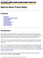
Lab Scenario 1 Frame Relay and OSPF
Introduction
This lab is designed to be a build-to-specifications test. There are numerous issues that need to be addressed for this
lab to work correctly. The lab is designed to illustrate some of the problems associated with NBMA networks and link-
state routing protocols such as OSPF. Although the lab specifications will require you to solve problems in ways that
you will probably never see in a production network, you will find that the same problem can be solved more than one
way, sometimes using layer 2 techniques and sometimes using layer 3 techniques. When you thoroughly understand
each method, then you will be prepared for any situation.
Network Specifications
When you are finished troubleshooting the network, it should meet the following specifications:
1. R1 must use a physical interface.
2. R3 must use a multipoint subinterface.
3. R4 must use a physical interface.
4. DO NOT use any PVCs or DLCIs except the ones indicated within the drawing.
5. Use OSPF exclusively as the routing protocol. Make all three routers members of area 0. You must use only
the nonbroadcast network type.
6. R3 must always be the designated router. R1 and R4 should never be eligible to be the designated router.
7. R1 may ONLY use a single frame relay map statement. (Hint, you need a layer 3 solution here)
8. R3 may NOT use frame-relay interface DLCI commands.
9. R4 must use a layer 2 technique to solve hub and spoke reachability problems. You may not use the same
technique you used on R1.
10. Make sure you can ping every serial interface and every loopback interface from all three routers.
11. Use the following address scheme for the loopback addresses:
Scenario 1: Frame Relay and OSPF
Introduction
Network Specifications
The Starting Configs
Frame Switch
Hints
Solution Revealed
Grading Yourself
Final Configurations
R1
R3
R4
Scenario 2: Troubleshooting
Introduction
Network Specifications
The Starting Configs
R1
R3
R4
Frame Switch
Hints
Faults Revealed
Grading Yourself
Final Configurations
R1
R3
R4
CertificationZone Page 2 of 21
/?Issue=12&IssueDate=05-01-2000&CP= 11/06/01
@. R1: interface loopback 0 ip address 132.4.1.1 255.255.255.0
a. R3: interface loopback 0 ip address 132.4.3.3 255.255.255.0
b. R4: interface loopback 0 ip address 132.4.4.4 255.255.255.0
12. Use the following address scheme for the serial interface addresses:
@. R1: interface serial 0 ip address 135.6.1.1 255.255.255.0
a. R3: interface serial 0 ip address 135.6.1.3 255.255.255.0
b. R4: interface serial 0 ip address 135.6.1.4 255.255.255.0
13. Configure R1 such that IP packets become discard eligible on the serial 0 interface for DLCI 110.
14. Configure a special broadcast queue on R4 to hold 80 packets and transmit at a rate of 64 packets per
second. The queue should restrict transmission to 124,000 bytes per second.
The Starting Configs
Since this is a construct-to-specifications sort of lab, I will only provide the frame-relay switch configuration.
Frame Switch
version 11.3
service nagle
!
hostname frameswitch
!
ip subnet-zero
ip tcp synwait-time 5
no ip domain-lookup
frame-relay switching
!
interface Ethernet0
no ip address
shutdown
!
interface Serial0
no ip address
CertificationZone Page 3 of 21
/?Issue=12&IssueDate=05-01-2000&CP= 11/06/01
shutdown
!
interface Serial1
no ip address
encapsulation frame-relay
frame-relay intf-type dce
frame-relay route 102 interface Serial5 201
frame-relay route 103 interface Serial3 301
!
interface Serial2
no ip address
shutdown
!
interface Serial3
no ip address
encapsulation frame-relay
clockrate 56000
frame-relay intf-type dce
frame-relay route 110 interface Serial5 101
frame-relay route 301 interface Serial1 103
!
interface Serial4
no ip address
shutdown
!
interface Serial5
no ip address
encapsulation frame-relay
clockrate 56000
frame-relay intf-type dce
frame-relay route 101 interface Serial3 110
frame-relay route 201 interface Serial1 102
!
ip classless
!
line con 0
privilege level 15
line aux 0
line vty 0 4
privilege level 15
no login
Hints
l Do we need to disable inverse-ARP to prevent DLCIs from being used?
l Even though OSPF uses multicasts to 224.0.0.5 and 224.0.0.6, do we need the broadcast parameter on frame
relay map statements? Yes, the broadcast parameter is used to cover both broadcasts and multicasts.
l Do we need to use an OSPF neighbor statement on the hub router?
l Would the OSPF priority command help with DR selection?
l Since R3 cannot use frame-relay interface DLCI commands, we must use frame-relay map statements.
l Since R3 is using a multipoint interface, and R1 and R4 are using physical interfaces, we have a problem with
network type mismatches. How can we make sure that R3 also uses the non-broadcast interface type? Maybe
the ip ospf network non-broadcast command under the sub-interface would help here.
l Since we need a layer 3 technique on R1 and are only permitted to use one frame relay map statement, how
can we make sure that the next hop for traffic destined for remote IP addresses is always sent to the hub?
Would IP policy routing help here?
l For R4, we can use multiple frame relay map statements to solve the hub spoke reachability problem using a
layer 2 technique.
l Make sure you can ping every serial interface and every loopback interface from all three routers.
CertificationZone Page 4 of 21
/?Issue=12&IssueDate=05-01-2000&CP= 11/06/01
Solution Revealed
Look at how there are no OSPF neighbors before we add the OSPF neighbor statements.
r3#sh ip ospf int s 0.2
Serial0.2 is up, line protocol is up
Internet Address 135.6.1.3/24, Area 0
Process ID 1, Router ID 132.4.3.3, Network Type NON_BROADCAST,
Cost: 64
Transmit Delay is 1 sec, State DR, Priority 200
Designated Router (ID) 132.4.3.3, Interface address 135.6.1.3
No backup designated router on this network
Timer intervals configured, Hello 30, Dead 120, Wait 120,
Retransmit 5
Hello due in 00:00:24
Neighbor Count is 0, Adjacent neighbor count is 0
Suppress hello for 0 neighbor(s)
r3#
Now look at the difference when we add a neighbor statement:
r3#conf t
Enter configuration commands, one per line. End with CNTL/Z.
r3(config)#router ospf 1
r3(config-router)#neigh
r3(config-router)#neighbor ?
A.B.C.D Neighbor address
r3(config-router)#neighbor 135.6.1.4 ?
poll-interval OSPF dead-router polling interval
priority OSPF priority of non-broadcast neighbor
<cr>
r3(config-router)#neighbor 135.6.1.4
r3(config-router)#
6d20h: OSPF: Starting 0.0.0.0 address 135.6.1.4 on Serial0.2^Z
r3#
6d20h: %SYS-5-CONFIG_I: Configured from console by console
6d20h: OSPF: Rcv hello from 132.4.4.4 area 0 from Serial0.2 135.6.1.4
6d20h: OSPF: 2 Way Communication to 132.4.4.4 on Serial0.2, state 2WAY
6d20h: OSPF: Neighbor change Event on interface Serial0.2
6d20h: OSPF: DR/BDR election on Serial0.2
6d20h: OSPF: Elect BDR 0.0.0.0
6d20h: OSPF: Elect DR 132.4.3.3
6d20h: DR: 132.4.3.3 (Id) BDR: none
6d20h: OSPF: Send DBD to 132.4.4.4 on Serial0.2 seq 0xB22 opt 0x2
flag 0x7 len 32
6d20h: OSPF: End of hello processing
6d20h: OSPF: Rcv DBD from 132.4.4.4 on Serial0.2 seq 0x1E2A opt 0x2
flag 0x7 len 32 state EXSTART
6d20h: OSPF: NBR Negotiation Done. We are the SLAVE
6d20h: OSPF: Send DBD to 132.4.4.4 on Serial0.2 seq 0x1E2A opt 0x2
flag 0x2 len52
6d20h: OSPF: Rcv DBD from 132.4.4.4 on Serial0.2 seq 0x1E2B opt 0x2
flag 0x3 len 52 state EXCHANGE
6d20h: OSPF: Send DBD to 132.4.4.4 on Serial0.2 seq 0x1E2B opt 0x2
flag 0x0 len 32
6d20h: OSPF: Database request to 132.4.4.4
6d20h: OSPF: sent LS REQ packet to 135.6.1.4, length 12
6d20h: OSPF: Rcv DBD from 132.4.4.4 on Serial0.2 seq 0x1E2C opt 0x2
flag 0x1 len 32 state EXCHANGE
6d20h: OSPF: Exchange Done with 132.4.4.4 on Serial0.2
6d20h: OSPF: Send DBD to 132.4.4.4 on Serial0.2 seq 0x1E2C opt 0x2
flag 0x0 len 32
6d20h: OSPF: Synchronized with 132.4.4.4 on Serial0.2, state FULL
6d20h: OSPF: Build router LSA for area 0, router ID 132.4.3.3
6d20h: OSPF: Build network LSA for Serial0.2, router ID 132.4.3.3
6d20h: OSPF: Rcv hello from 132.4.4.4 area 0 from Serial0.2 135.6.1.4
6d20h: OSPF: Neighbor change Event on interface Serial0.2
6d20h: OSPF: DR/BDR election on Serial0.2
6d20h: OSPF: Elect BDR 0.0.0.0
CertificationZone Page 5 of 21
/?Issue=12&IssueDate=05-01-2000&CP= 11/06/01
6d20h: OSPF: Elect DR 132.4.3.3
6d20h: DR: 132.4.3.3 (Id) BDR: none
Now look at the results of the show ip ospf interface s 0.2 on R3. Notice that R3 is the DR and that the OSPF priority
is 200. Notice that the network type is non-broadcast.
r3#sh ip ospf int s 0.2
Serial0.2 is up, line protocol is up
Internet Address 135.6.1.3/24, Area 0
Process ID 1, Router ID 132.4.3.3, Network Type NON_BROADCAST,
Cost: 64
Transmit Delay is 1 sec, State DR, Priority 200
Designated Router (ID) 132.4.3.3, Interface address 135.6.1.3
No backup designated router on this network
Timer intervals configured, Hello 30, Dead 120, Wait 120,
Retransmit 5
Hello due in 00:00:13
Neighbor Count is 1, Adjacent neighbor count is 1
Adjacent with neighbor 132.4.4.4
Suppress hello for 0 neighbor(s)
r3#
Look at the results from R1 with policy routing enabled:
r1#debug ip policy
Policy routing debugging is on
r1#ping 135.6.1.4
Type escape sequence to abort.
Sending 5, 100-byte ICMP Echos to 135.6.1.4, timeout is 2 seconds:
!!!!!
Success rate is 100 percent (5/5),
round-trip min/avg/max = 140/143/144 ms
r1#
6d21h: IP: s=135.6.1.1 (local), d=135.6.1.4, len 100, policy match
6d21h: IP: route map layer3, item 10, permit
6d21h: IP: s=135.6.1.1 (local), d=135.6.1.4 (Serial0), len 100,
policy routed
6d21h: IP: local to Serial0 135.6.1.1
6d21h: IP: s=135.6.1.4 (Serial0), d=135.6.1.1 (Serial0), len 100,
policy rejected normal forwarding
r1#
Notice on R1 that the ospf priority is 1 and R1 has become the designated router because at this point the adjacency
has not yet formed with R3.
CertificationZone Page 6 of 21
/?Issue=12&IssueDate=05-01-2000&CP= 11/06/01
r1#sh ip ospf int s 0
Serial0 is up, line protocol is up
Internet Address 135.6.1.1/24, Area 0
Process ID 1, Router ID 132.4.1.1, Network Type NON_BROADCAST,
Cost: 64
Transmit Delay is 1 sec, State DR, Priority 1
Designated Router (ID) 132.4.1.1, Interface address 135.6.1.1
No backup designated router on this network
Timer intervals configured, Hello 30, Dead 120, Wait 120,
Retransmit 5
Hello due in 00:00:11
Neighbor Count is 0, Adjacent neighbor count is 0
Suppress hello for 0 neighbor(s)
r1#
Now look at the results once we have set the OSPF priority to 0 on R1. Notice that because of the policy routing,
adjacencies are formed and we do not need an OSPF neighbor statement for R1 on R3.
r1#sh ip ospf int s 0
Serial0 is up, line protocol is up
Internet Address 135.6.1.1/24, Area 0
Process ID 1, Router ID 132.4.1.1, Network Type NON_BROADCAST,
Cost: 64
Transmit Delay is 1 sec, State DROTHER, Priority 0
Designated Router (ID) 132.4.3.3, Interface address 135.6.1.3
No backup designated router on this network
Timer intervals configured, Hello 30, Dead 120, Wait 120,
Retransmit 5
Hello due in 00:00:17
Neighbor Count is 1, Adjacent neighbor count is 1
Adjacent with neighbor 132.4.3.3 (Designated Router)
Suppress hello for 0 neighbor(s)
r1#
Grading Yourself
If you have disabled inverse arp correctly, then you will see the following on R1:
r1#sh frame pvc
PVC Statistics for interface Serial0 (Frame Relay DTE)
DLCI = 110, DLCI USAGE = LOCAL, PVC STATUS = ACTIVE,
INTERFACE = Serial0.1
input pkts 7 output pkts 15 in bytes 288
out bytes 1955 dropped pkts 1 in FECN pkts 0
in BECN pkts 0 out FECN pkts 0 out BECN pkts 0
in DE pkts 0 out DE pkts 0
out bcast pkts 15 out bcast bytes 1955
pvc create time 3d19h, last time pvc status
changed 00:00:27
DLCI = 301, DLCI USAGE = UNUSED, PVC STATUS = ACTIVE,
INTERFACE = Serial0
input pkts 3 output pkts 0 in bytes 90
out bytes 0 dropped pkts 1 in FECN pkts 0
in BECN pkts 0 out FECN pkts 0 out BECN pkts 0
in DE pkts 0 out DE pkts 0
out bcast pkts 0 out bcast bytes 0 Num Pkts Switched 0
pvc create time 00:26:28, last time pvc status
changed 00:00:29
If you have the correct LMI-type on R1, then you will see that the LMI type is CISCO:
r1#sh frame lmi
LMI Statistics for interface Serial0 (Frame Relay DTE)
CertificationZone Page 7 of 21
/?Issue=12&IssueDate=05-01-2000&CP= 11/06/01
LMI TYPE = CISCO
Invalid Unnumbered info 0 Invalid Prot Disc 0
Invalid dummy Call Ref 0 Invalid Msg Type 0
Invalid Status Message 0 Invalid Lock Shift 0
Invalid Information ID 0 Invalid Report IE Len 0
Invalid Report Request 0 Invalid Keep IE Len 0
Num Status Enq. Sent 32929 Num Status msgs Rcvd 63
Num Update Status Rcvd 0 Num Status Timeouts 32867
If you have the frame relay encapsulation configured correctly, then you will see "Encapsulation FRAME-RELAY", as
shown below, rather than "Encapsulation FRAME-RELAY IETF".
r3#sh int s 0.2
Serial0.2 is up, line protocol is up
Hardware is HD64570
Internet address is 135.6.1.3/24
MTU 1500 bytes, BW 1544 Kbit, DLY 20000 usec,
rely 255/255, load 1/255
Encapsulation FRAME-RELAY
Since RIPv2 is a distance vector protocol, split-horizon must be disabled on multipoint subinterfaces. Note that with
physical interfaces, split-horizon is automatically disabled for IP. You can confirm that ip split-horizon is disabled
using the show ip interface command as seen below:
r3#sh ip int s 0.2
Serial0.2 is up, line protocol is up
Internet address is 135.6.1.3/24
Broadcast address is 255.255.255.255
Address determined by non-volatile memory
MTU is 1500 bytes
Helper address is not set
Directed broadcast forwarding is enabled
Multicast reserved groups joined: 224.0.0.9
Outgoing access list is not set
Inbound access list is not set
Proxy ARP is enabled
Security level is default
Split horizon is disabled
ICMP redirects are always sent
ICMP unreachables are always sent
ICMP mask replies are never sent
IP fast switching is enabled
IP fast switching on the same interface is enabled
IP multicast fast switching is enabled
Router Discovery is disabled
IP output packet accounting is disabled
IP access violation accounting is disabled
TCP/IP header compression is disabled
Probe proxy name replies are disabled
Gateway Discovery is disabled
Policy routing is disabled
Network address translation is disabled
You can confirm that RIP version 2 is being used by examining the results of the show ip protocols command. Note
the send version and receive version below:
r3#sh ip prot
Routing Protocol is "rip"
Sending updates every 30 seconds, next due in 18 seconds
Invalid after 180 seconds, hold down 180, flushed after 240
Outgoing update filter list for all interfaces is
Incoming update filter list for all interfaces is
Redistributing: rip
Default version control: send version 2, receive version 2
Interface Send Recv Key-chain
Ethernet1 2 2
Loopback0 2 2
Serial0.2 2 2
Serial1 2 2
Routing for Networks:
132.4.0.0
CertificationZone Page 8 of 21
/?Issue=12&IssueDate=05-01-2000&CP= 11/06/01
135.6.0.0
Routing Information Sources:
Gateway Distance Last Update
135.6.1.1 120 00:00:01
135.6.1.4 120 00:00:07
Distance: (default is 120)
IP Routing Tables
r1#sh ip route
Codes: C - connected, S - static, I - IGRP,
R - RIP, M - mobile, B - BGP
D - EIGRP, EX - EIGRP external,
O - OSPF, IA - OSPF inter area
N1 - OSPF NSSA external type 1,
N2 - OSPF NSSA external type 2
E1 - OSPF external type 1,
E2 - OSPF external type 2, E - EGP
i - IS-IS, L1 - IS-IS level-1,
L2 - IS-IS level-2, * - candidate default
U - per-user static route, o - ODR
Gateway of last resort is not set
132.4.0.0/16 is variably subnetted, 2 subnets, 2 masks
R 132.4.0.0/16 [120/1] via 135.6.1.3, 00:00:17, Serial0.1
C 132.4.1.0/24 is directly connected, Loopback0
135.6.0.0/24 is subnetted, 1 subnets
C 135.6.1.0 is directly connected, Serial0.1
r1#
r3#sh ip route
Codes: C - connected, S - static, I - IGRP,
R - RIP, M - mobile, B - BGP
D - EIGRP, EX - EIGRP external,
O - OSPF, IA - OSPF inter area
N1 - OSPF NSSA external type 1,
N2 - OSPF NSSA external type 2
E1 - OSPF external type 1,
E2 - OSPF external type 2, E - EGP
i - IS-IS, L1 - IS-IS level-1,
L2 - IS-IS level-2, * - candidate default
U - per-user static route, o - ODR
Gateway of last resort is not set
132.4.0.0/16 is variably subnetted, 2 subnets, 2 masks
R 132.4.0.0/16 [120/1] via 135.6.1.1, 00:00:06, Serial0.2
[120/1] via 135.6.1.4, 00:00:07, Serial0.2
C 132.4.3.0/24 is directly connected, Loopback0
135.6.0.0/24 is subnetted, 1 subnets
C 135.6.1.0 is directly connected, Serial0.2
r3#
r4#sh ip route
Codes: C - connected, S - static, I - IGRP,
R - RIP, M - mobile, B - BGP
D - EIGRP, EX - EIGRP external,
O - OSPF, IA - OSPF inter area
N1 - OSPF NSSA external type 1,
N2 - OSPF NSSA external type 2
E1 - OSPF external type 1,
E2 - OSPF external type 2, E - EGP
i - IS-IS, L1 - IS-IS level-1,
L2 - IS-IS level-2, * - candidate default
U - per-user static route, o - ODR
Gateway of last resort is not set
11.0.0.0/24 is subnetted, 1 subnets
C 11.0.0.0 is directly connected, BRI0
132.4.0.0/16 is variably subnetted, 2 subnets, 2 masks
R 132.4.0.0/16 [120/1] via 135.6.1.3, 00:00:05, Serial0
C 132.4.4.4/32 is directly connected, Loopback0
135.6.0.0/24 is subnetted, 1 subnets
CertificationZone Page 9 of 21
/?Issue=12&IssueDate=05-01-2000&CP= 11/06/01
C 135.6.1.0 is directly connected, Serial0
r4#
Final Configurations
R1
version 11.3
service nagle
!
hostname r1
!
ip subnet-zero
ip tcp synwait-time 5
no ip domain-lookup
frame-relay de-list 1 protocol ip
!
interface Loopback0
ip address 132.4.1.1 255.255.255.0
!
interface Ethernet0
ip address 150.100.2.1 255.255.255.0
no lat enabled
!
interface Serial0
ip address 135.6.1.1 255.255.255.0
encapsulation frame-relay
ip ospf priority 0
no ip mroute-cache
ip policy route-map layer3
frame-relay de-group 1 110
frame-relay map ip 135.6.1.3 110 broadcast
no frame-relay inverse-arp
!
interface Serial1
no ip address
shutdown
!
router ospf 1
network 132.4.1.1 0.0.0.0 area 0
network 135.6.1.0 0.0.0.255 area 0
!
ip local policy route-map layer3
ip classless
!
access-list 101 permit ip any host 135.6.1.4
access-list 101 permit ip any 132.4.4.0 0.0.0.255
access-list 101 permit ip any 132.4.3.0 0.0.0.255
route-map layer3 permit 10
match ip address 101
set ip next-hop 135.6.1.3
!
alias exec i show ip route
alias exec br show ip int brief
alias exec s show ses
alias exec r show run
!
ip classless
!
line con 0
exec-timeout 5 0
privilege level 15
logging synchronous
line 1 8
modem Host
transport input all
line 9 16
line aux 0
line vty 0 4
exec-timeout 5 0
privilege level 15
no login
!
CertificationZone Page 10 of 21
/?Issue=12&IssueDate=05-01-2000&CP= 11/06/01
end
R3
version 11.3
service nagle
!
hostname r3
!
ip subnet-zero
ip tcp synwait-time 5
no ip domain-lookup
!
interface Loopback0
ip address 132.4.3.3 255.255.255.0
!
interface Ethernet0
no ip address
shutdown
!
interface Ethernet1
ip address 132.4.16.3 255.255.255.224
!
interface Serial0
no ip address
encapsulation frame-relay
no ip mroute-cache
!
interface Serial0.2 multipoint
ip address 135.6.1.3 255.255.255.0
no ip split-horizon
ip ospf priority 200
frame-relay map ip 135.6.1.1 101 broadcast
frame-relay map ip 135.6.1.4 201 broadcast
!
interface Serial1
ip address 132.4.64.5 255.255.240.0
no ip mroute-cache
clockrate 56000
!
router ospf 1
network 132.4.3.3 0.0.0.0 area 0
network 135.6.1.0 0.0.0.255 area 0
!
ip classless
!
line con 0
exec-timeout 5 0
privilege level 15
line aux 0
line vty 0 4
exec-timeout 5 0
privilege level 15
no login
!
end
R4
version 11.3
service nagle
!
hostname r4
!
ip subnet-zero
ip tcp synwait-time 5
no ip domain-lookup
isdn switch-type basic-ni1
!
interface Loopback0
ip address 132.4.4.4 255.255.255.255
!
interface Serial0
CertificationZone Page 11 of 21
/?Issue=12&IssueDate=05-01-2000&CP= 11/06/01
ip address 135.6.1.4 255.255.255.0
encapsulation frame-relay
clockrate 56000
frame-relay broadcast-queue 80 124000 64
frame-relay map ip 135.6.1.1 102 broadcast
frame-relay map ip 135.6.1.3 102 broadcast
no frame-relay inverse-arp
!
interface Serial1
no ip address
shutdown
!
interface TokenRing0
no ip address
ring-speed 16
!
router ospf 1
network 132.4.4.4 0.0.0.0 area 0
network 135.6.1.0 0.0.0.255 area 0
!
ip classless
!
line con 0
exec-timeout 5 0
privilege level 15
line aux 0
line vty 0 4
exec-timeout 5 0
privilege level 15
no login
!
end
Lab Scenario 2 Troubleshooting
Introduction
This lab is designed to be a strong test of your frame-relay skills. There are numerous faults inserted on each router. I
chose to use RIP version 2 as the routing protocol to familiarize the reader with the differences from ordinary RIP or
RIP version 1, as well as the problems a distance vector routing protocol causes in an NBMA network. This lab is also
designed to test your knowledge of practical matters such as frame relay switch configuration, LMI type, frame relay
encapsulation, as well as the way the different interface types compare to each other. Note that there are no faults in
the frame-relay switch configuration provided.
Network Specifications
When you are finished troubleshooting the network, it should meet the following specifications:
0. R1 should use a point-to-point subinterface.
1. R3 should use a multipoint subinterface.
2. R4 should use a physical interface.
3. DO NOT use any PVCs or DLCIs except the ones indicated within the drawing.
4. Use RIP version 2 exclusively as the routing protocol.
5. DO NOT use IETF frame relay encapsulation.
6. Make sure you can ping every serial interface and every loopback interface from all three routers.
7. Use the following address scheme for the loopback addresses:
CertificationZone Page 12 of 21
/?Issue=12&IssueDate=05-01-2000&CP= 11/06/01
@. R1: interface loopback 0 ip address 132.4.1.1 255.255.255.0
a. R3: interface loopback 0 ip address 132.4.3.3 255.255.255.0
b. R4: interface loopback 0 ip address 132.4.4.4 255.255.255.0
8. Use the following address scheme for the serial interface addresses:
@. R1: interface serial 0 ip address 135.6.1.1 255.255.255.0
a. R3: interface serial 0 ip address 135.6.1.3 255.255.255.0
b. R4: interface serial 0 ip address 135.6.1.4 255.255.255.0
The Starting Configs
You can work on this lab in several ways, but the best way is to just write erase your routers and paste in the
configurations below. An alternative method is to analyze the configurations, spot the faults, manually enter the
corrected configurations, and then test that they are correct.
R1
version 11.3
service nagle
!
hostname r1
!
ip subnet-zero
ip tcp synwait-time 5
no ip domain-lookup
!
interface Loopback0
ip address 132.4.1.1 255.255.255.0
!
interface Ethernet0
ip address 150.100.2.1 255.255.255.0
!
interface Serial0
no ip address
encapsulation frame-relay
frame-relay lmi-type ansi
!
CertificationZone Page 13 of 21
/?Issue=12&IssueDate=05-01-2000&CP= 11/06/01
interface Serial0.1 point-to-point
ip address 135.6.1.1 255.255.255.0
frame-relay interface-dlci 110
!
interface Serial1
no ip address
shutdown
!
router rip
version 2
network 132.4.0.0
network 135.6.0.0
!
ip classless
!
line con 0
exec-timeout 5 0
privilege level 15
logging synchronous
line 1 8
modem Host
transport input all
line 9 16
line aux 0
line vty 0 4
exec-timeout 5 0
privilege level 15
no login
!
end
R3
version 11.3
service nagle
!
hostname r3
!
ip subnet-zero
ip tcp synwait-time 5
no ip domain-lookup
!
interface Loopback0
ip address 132.4.3.3 255.255.255.0
!
interface Ethernet0
no ip address
shutdown
!
interface Ethernet1
ip address 132.4.16.3 255.255.255.224
!
interface Serial0
no ip address
encapsulation frame-relay IETF
!
interface Serial0.2 multipoint
ip address 135.6.1.3 255.255.255.0
frame-relay interface-dlci 101
frame-relay interface-dlci 201
!
interface Serial1
ip address 132.4.64.5 255.255.240.0
no ip mroute-cache
clockrate 56000
!
router rip
version 2
network 132.4.0.0
network 135.6.0.0
ip classless
!
line con 0
exec-timeout 5 0
CertificationZone Page 14 of 21
/?Issue=12&IssueDate=05-01-2000&CP= 11/06/01
privilege level 15
line aux 0
line vty 0 4
exec-timeout 5 0
privilege level 15
no login
end
R4
version 11.3
service nagle
!
hostname r4
!
ip subnet-zero
ip tcp synwait-time 5
no ip domain-lookup
!
interface Loopback0
ip address 132.4.4.4 255.255.255.255
!
interface Serial0
ip address 135.6.1.4 255.255.255.0
encapsulation frame-relay
clockrate 56000
frame-relay map ip 135.6.1.3 102
!
interface Serial1
no ip address
shutdown
!
interface TokenRing0
no ip address
shutdown
ring-speed 16
!
interface BRI0
no ip address
shutdown
!
router rip
network 132.4.0.0
network 135.6.0.0
!
ip classless
!
line con 0
exec-timeout 5 0
privilege level 15
line aux 0
line vty 0 4
exec-timeout 5 0
privilege level 15
no login
!
end
Frame Switch
version 11.3
service nagle
!
hostname frameswitch
!
ip subnet-zero
ip tcp synwait-time 5
no ip domain-lookup
frame-relay switching
!
interface Ethernet0
no ip address
shutdown
CertificationZone Page 15 of 21
/?Issue=12&IssueDate=05-01-2000&CP= 11/06/01
!
interface Serial0
no ip address
shutdown
!
interface Serial1
no ip address
encapsulation frame-relay
frame-relay intf-type dce
frame-relay route 102 interface Serial5 201
frame-relay route 103 interface Serial3 301
!
interface Serial2
no ip address
shutdown
!
interface Serial3
no ip address
encapsulation frame-relay
clockrate 56000
frame-relay intf-type dce
frame-relay route 110 interface Serial5 101
frame-relay route 301 interface Serial1 103
!
interface Serial4
no ip address
shutdown
!
interface Serial5
no ip address
encapsulation frame-relay
clockrate 56000
frame-relay intf-type dce
frame-relay route 101 interface Serial3 110
frame-relay route 201 interface Serial1 102
!
ip classless
!
line con 0
privilege level 15
line aux 0
line vty 0 4
privilege level 15
no login
Hints
l Before you troubleshoot layer 3 problems, make sure layer 2 problems are corrected.
l Are the LMI types correct? Why not let autosense choose the correct LMI type as long as your IOS is version
11.2 or greater? The default LMI type is Cisco. Other less common types are ANSI and q933a. If no LMI type
is specified on the frame relay switch, then the LMI type will default to Cisco.
l Are you using the correct frame-relay encapsulation? The default encapsulation type is Cisco. IETF is used
mainly to connect to non-Cisco routers.
l What is the difference between RIP version 1 and RIP version 2?
l Is RIP a distance vector protocol, or is RIP a link-state protocol?
l What problem does a distance vector protocol cause on a multipoint sub-interface or physical interface?
l When you enter the interface configuration command "encapsulation frame-relay," what happens on a
physical interface? What happens on a sub-interface? When you enter the command "encapsulation frame-
relay" IP split-horizon is automatically disabled ONLY on a physical interface. Under sub-interfaces, IP split-
horizon will remain enabled. If you want to disable IP split-horizon on a multipoint sub-interface, then you must
manually issue the command "no ip split-horizon" under the multipoint sub-interface.
l Since the switch is fully meshed, how do we disable PVCs we do not wish to use? We prevent PVCs from
being used by issuing the "no frame-relay inverse-arp" command. We must then configure frame relay map
CertificationZone Page 16 of 21
/?Issue=12&IssueDate=05-01-2000&CP= 11/06/01
statements or frame relay interface DLCI commands for the PVCs and DLCIs you want to use.
l Is RIP a broadcast dependent protocol? Yes, it is, so you need the broadcast parameter on your frame relay
map statements.
l How many frame relay map statements will you need? With a physical interface, you need a frame relay map
statement for every PVC and IP address on the frame relay subnet.
l Can we rely on inverse arp in a hub-and-spoke or partial-mesh frame-relay network or must we use map
statements? You can only use inverse arp on the hub. Do you know why? For the spokes we must use map
statements.
Faults Revealed
• R1: Wrong LMI-type, should be cisco or let autosense, not q933a.
• R1: Need to disable inverse arp to prevent the extra pvc from being used.
• R3: Wrong frame-relay encapsulation, should not have ietf.
• R3: ip split-horizon is not disabled.
• R4: Wrong version of rip, should be version 2.
• R4: Existing frame-relay map statement is missing the broadcast parameter.
• R4: Needs an additional frame relay map statement to R1 with broadcast parameter.
• R4: Need to disable inverse arp to prevent the extra pvc from being used.
Grading Yourself
If you have disabled inverse arp correctly, then you will see the following on R1:
r1#sh frame pvc
PVC Statistics for interface Serial0 (Frame Relay DTE)
DLCI = 110, DLCI USAGE = LOCAL, PVC STATUS = ACTIVE,
INTERFACE = Serial0.1
input pkts 7 output pkts 15 in bytes 288
out bytes 1955 dropped pkts 1 in FECN pkts 0
in BECN pkts 0 out FECN pkts 0 out BECN pkts 0
in DE pkts 0 out DE pkts 0
out bcast pkts 15 out bcast bytes 1955
pvc create time 3d19h, last time pvc status changed 00:00:27
DLCI = 301, DLCI USAGE = UNUSED, PVC STATUS = ACTIVE,
INTERFACE = Serial0
input pkts 3 output pkts 0 in bytes 90
out bytes 0 dropped pkts 1 in FECN pkts 0
in BECN pkts 0 out FECN pkts 0 out BECN pkts 0
in DE pkts 0 out DE pkts 0
out bcast pkts 0 out bcast bytes 0 Num Pkts Switched 0
pvc create time 00:26:28, last time pvc status
changed 00:00:29
If you have the correct LMI-type on R1, then you will see that the LMI type is CISCO:
r1#sh frame lmi
CertificationZone Page 17 of 21
/?Issue=12&IssueDate=05-01-2000&CP= 11/06/01
LMI Statistics for interface Serial0
(Frame Relay DTE) LMI TYPE = CISCO
Invalid Unnumbered info 0 Invalid Prot Disc 0
Invalid dummy Call Ref 0 Invalid Msg Type 0
Invalid Status Message 0 Invalid Lock Shift 0
Invalid Information ID 0 Invalid Report IE Len 0
Invalid Report Request 0 Invalid Keep IE Len 0
Num Status Enq. Sent 32929 Num Status msgs Rcvd 63
Num Update Status Rcvd 0 Num Status Timeouts 32867
If you have the frame relay encapsulation configured correctly, then you will see "Encapsulation FRAME-RELAY", as
shown below, rather than "Encapsulation FRAME-RELAY IETF".
r3#sh int s 0.2
Serial0.2 is up, line protocol is up
Hardware is HD64570
Internet address is 135.6.1.3/24
MTU 1500 bytes, BW 1544 Kbit, DLY 20000 usec,
rely 255/255, load 1/255
Encapsulation FRAME-RELAY
Since RIPv2 is a distance vector protocol, split-horizon must be disabled on multipoint subinterfaces. Note that with
physical interfaces, split-horizon is automatically disabled for IP. You can confirm that ip split-horizon is disabled
using the show ip interface command as seen below:
r3#sh ip int s 0.2
Serial0.2 is up, line protocol is up
Internet address is 135.6.1.3/24
Broadcast address is 255.255.255.255
Address determined by non-volatile memory
MTU is 1500 bytes
Helper address is not set
Directed broadcast forwarding is enabled
Multicast reserved groups joined: 224.0.0.9
Outgoing access list is not set
Inbound access list is not set
Proxy ARP is enabled
Security level is default
Split horizon is disabled
ICMP redirects are always sent
ICMP unreachables are always sent
ICMP mask replies are never sent
IP fast switching is enabled
IP fast switching on the same interface is enabled
IP multicast fast switching is enabled
Router Discovery is disabled
IP output packet accounting is disabled
IP access violation accounting is disabled
TCP/IP header compression is disabled
Probe proxy name replies are disabled
Gateway Discovery is disabled
Policy routing is disabled
Network address translation is disabled
You can confirm that RIP version 2 is being used by examining the results of the show ip protocols command. Note
the send version and receive versions below:
r3#sh ip prot
Routing Protocol is "rip"
Sending updates every 30 seconds, next due in 18 seconds
Invalid after 180 seconds, hold down 180, flushed after 240
Outgoing update filter list for all interfaces is
Incoming update filter list for all interfaces is
Redistributing: rip
Default version control: send version 2, receive version 2
Interface Send Recv Key-chain
Ethernet1 2 2
Loopback0 2 2
Serial0.2 2 2
Serial1 2 2
Routing for Networks:
132.4.0.0
CertificationZone Page 18 of 21
/?Issue=12&IssueDate=05-01-2000&CP= 11/06/01
135.6.0.0
Routing Information Sources:
Gateway Distance Last Update
135.6.1.1 120 00:00:01
135.6.1.4 120 00:00:07
Distance: (default is 120)
IP Routing Tables
r1#sh ip route
Codes: C - connected, S - static, I - IGRP,
R - RIP, M - mobile, B - BGP
D - EIGRP, EX - EIGRP external,
O - OSPF, IA - OSPF inter area
N1 - OSPF NSSA external type 1,
N2 - OSPF NSSA external type 2
E1 - OSPF external type 1,
E2 - OSPF external type 2, E - EGP
i - IS-IS, L1 - IS-IS level-1,
L2 - IS-IS level-2, * - candidate default
U - per-user static route, o - ODR
Gateway of last resort is not set
132.4.0.0/16 is variably subnetted, 2 subnets, 2 masks
R 132.4.0.0/16 [120/1] via 135.6.1.3, 00:00:17, Serial0.1
C 132.4.1.0/24 is directly connected, Loopback0
135.6.0.0/24 is subnetted, 1 subnets
C 135.6.1.0 is directly connected, Serial0.1
r1#
r3#sh ip route
Codes: C - connected, S - static, I - IGRP,
R - RIP, M - mobile, B - BGP
D - EIGRP, EX - EIGRP external,
O - OSPF, IA - OSPF inter area
N1 - OSPF NSSA external type 1,
N2 - OSPF NSSA external type 2
E1 - OSPF external type 1,
E2 - OSPF external type 2, E - EGP
i - IS-IS, L1 - IS-IS level-1,
L2 - IS-IS level-2, * - candidate default
U - per-user static route, o - ODR
Gateway of last resort is not set
132.4.0.0/16 is variably subnetted, 2 subnets, 2 masks
R 132.4.0.0/16 [120/1] via 135.6.1.1, 00:00:06, Serial0.2
[120/1] via 135.6.1.4, 00:00:07, Serial0.2
C 132.4.3.0/24 is directly connected, Loopback0
135.6.0.0/24 is subnetted, 1 subnets
C 135.6.1.0 is directly connected, Serial0.2
r3#
r4#sh ip route
Codes: C - connected, S - static, I - IGRP,
R - RIP, M - mobile, B - BGP
D - EIGRP, EX - EIGRP external,
O - OSPF, IA - OSPF inter area
N1 - OSPF NSSA external type 1,
N2 - OSPF NSSA external type 2
E1 - OSPF external type 1,
E2 - OSPF external type 2, E - EGP
i - IS-IS, L1 - IS-IS level-1,
L2 - IS-IS level-2, * - candidate default
U - per-user static route, o - ODR
Gateway of last resort is not set
11.0.0.0/24 is subnetted, 1 subnets
C 11.0.0.0 is directly connected, BRI0
132.4.0.0/16 is variably subnetted, 2 subnets, 2 masks
R 132.4.0.0/16 [120/1] via 135.6.1.3, 00:00:05, Serial0
C 132.4.4.4/32 is directly connected, Loopback0
135.6.0.0/24 is subnetted, 1 subnets
CertificationZone Page 19 of 21
/?Issue=12&IssueDate=05-01-2000&CP= 11/06/01
C 135.6.1.0 is directly connected, Serial0
r4#
Final Configurations
R1
version 11.3
service nagle
!
hostname r1
!
ip subnet-zero
ip tcp synwait-time 5
no ip domain-lookup
!
interface Loopback0
ip address 132.4.1.1 255.255.255.0
!
interface Ethernet0
ip address 150.100.2.1 255.255.255.0
no lat enabled
!
interface Serial0
no ip address
encapsulation frame-relay
no frame-relay inverse-arp
!
interface Serial0.1 point-to-point
ip address 135.6.1.1 255.255.255.0
frame-relay interface-dlci 110
!
interface Serial1
no ip address
shutdown
!
router rip
version 2
network 132.4.0.0
network 135.6.0.0
!
ip classless
!
line con 0
exec-timeout 5 0
privilege level 15
logging synchronous
line 1 8
modem Host
transport input all
line 9 16
line aux 0
line vty 0 4
exec-timeout 5 0
privilege level 15
no login
!
end
R3
version 11.3
service nagle
!
hostname r3
!
ip subnet-zero
ip tcp synwait-time 5
no ip domain-lookup
!
interface Loopback0
CertificationZone Page 20 of 21
/?Issue=12&IssueDate=05-01-2000&CP= 11/06/01
ip address 132.4.3.3 255.255.255.0
!
interface Ethernet0
no ip address
shutdown
!
interface Ethernet1
ip address 132.4.16.3 255.255.255.224
!
interface Serial0
no ip address
encapsulation frame-relay
!
interface Serial0.2 multipoint
ip address 135.6.1.3 255.255.255.0
no ip split-horizon
frame-relay interface-dlci 101
frame-relay interface-dlci 201
!
interface Serial1
ip address 132.4.64.5 255.255.240.0
no ip mroute-cache
clockrate 56000
!
router rip
version 2
network 132.4.0.0
network 135.6.0.0
!
ip classless
!
line con 0
exec-timeout 5 0
privilege level 15
line aux 0
line vty 0 4
exec-timeout 5 0
privilege level 15
no login
!
end
R4
version 11.3
service nagle
!
hostname r4
!
ip subnet-zero
ip tcp synwait-time 5
no ip domain-lookup
isdn switch-type basic-ni1
!
interface Loopback0
ip address 132.4.4.4 255.255.255.255
!
interface Serial0
ip address 135.6.1.4 255.255.255.0
encapsulation frame-relay
clockrate 56000
frame-relay map ip 135.6.1.1 102 broadcast
frame-relay map ip 135.6.1.3 102 broadcast
no frame-relay inverse-arp
!
interface Serial1
no ip address
shutdown
!
interface TokenRing0
no ip address
ring-speed 16
!
router rip
CertificationZone Page 21 of 21
/?Issue=12&IssueDate=05-01-2000&CP= 11/06/01
version 2
network 132.4.0.0
network 135.6.0.0
!
ip classless
!
dialer-list 1 protocol ip permit
!
line con 0
exec-timeout 5 0
privilege level 15
line aux 0
line vty 0 4
exec-timeout 5 0
privilege level 15
no login
!
end
[IE-FRAME-LS1&2-F03]
[2000-05-03-01]
Copyright © 2000 Genium Publishing Corporation